
Tatijana Stewart • BArch 2021 • Princeton University School of Architecture
Don't wanna be here? Send us removal request.
Statistics
We looked inside some of the posts by sunfold and here's what we found interesting.
Average Info
Notes Per Post
16
Likes Per Post
1
Reblog Per Post
15
Reply Per Post
0
Time Between Posts
7 days
Number of Posts By Type
Photo
10
Text
2
Last Seen Tumblr Blogs


Fun Fact
Tumblr was attacked by a cross-site scripting worm deployed by the Internet troll group GNAA on Dec 3, 2012.
Photo
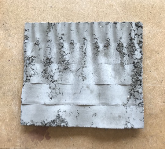
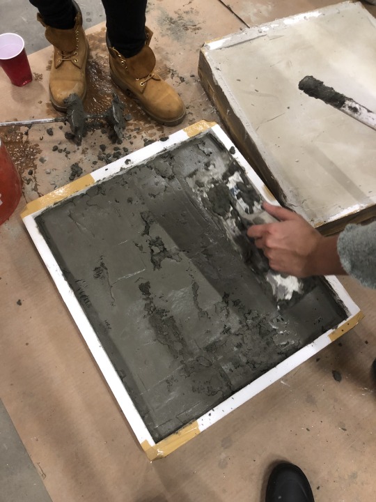
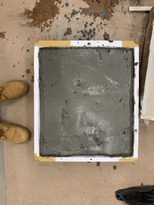
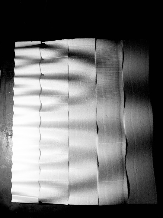
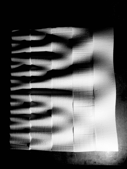
exercise 7. part 2 - cast
Work done in collaboration with Annette Chu ‘20 and Halima Matthews ‘21.
This is a continuation of the work done in exercise 7. part 1 cut +cast.
location - Princeton University Embodied Computation Lab (ECL)
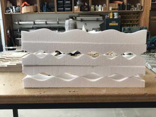
materials - foam for mold, concrete for casted object.
dimensions - Five panels of 4″ x 4″ x 24″ each, for a total dimension of 4″ x 20″ x 24″. Concrete thickness is variable along surface, between 1″ and 3″.
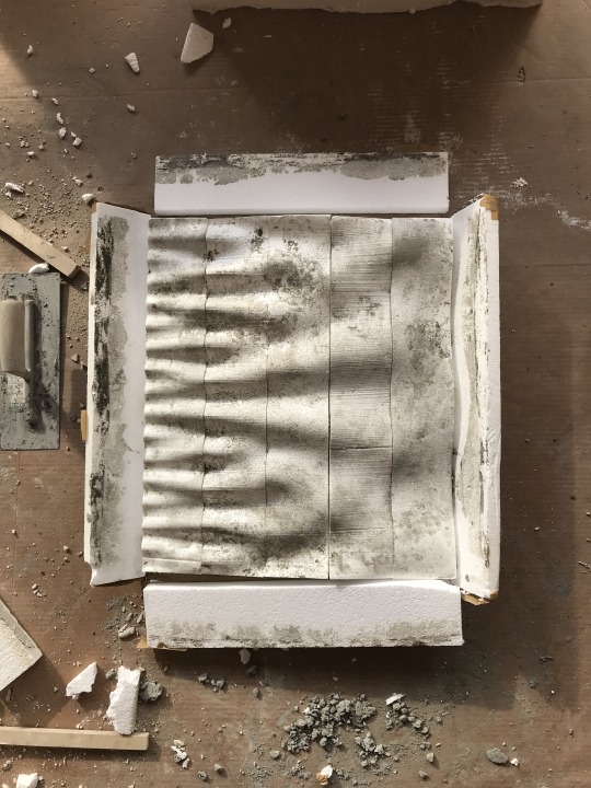
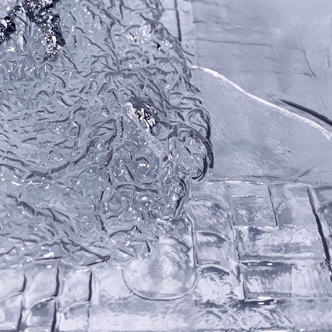
In the final step of this exercise, the assembled foam piece was prepared for concrete casting by being treated with cooking oil (to act as a release agent, Deplazes p. 64) and sealed tight using tape in order to prevent leaking and minimize honeycombing. Two separate study objects were produced (fig. 1 and fig. 7). Fig. 1 was the original mold created in exercise 7. part 1 while the object in fig. 7 was a study utilizing the the two end-piece negatives.
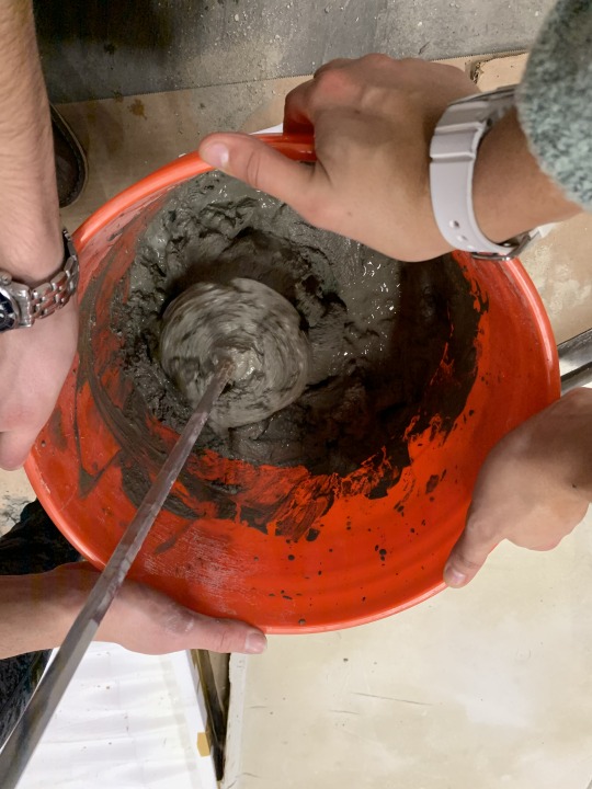
Concrete is a mixture consisting of cement, water, and coarse/fine aggregates. Deplazes notes that the water/cement ratio is critical to maintaining functional integrity of the concrete mixture. Ideally, the ratio should exist somewhere between a .45 and .55 water-to-cement ratio. “W/c ratios >.60 should be avoided.” (Deplazes, p. 66). In normal construction situations, the specifics of this ratio become a matter of cost versus strength. Less water means more cement and a stronger bonded concrete. More water means a more economically priced mixture, as cement is the expensive material ingredient.
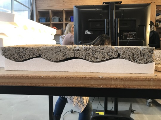
Though Deplazes mentions the upper limit of water content, in fig. 7, the effects of a low ratio (and flawed procedure) were realized. As a result of inaccuracies in w/c measurement and an attempted quick-fix that involved the dumping of excess water from the mixture, the concrete was too brittle once it cured and therefore lacked tensile strength, cracking once it was removed from the foam base. In the picture it is clear that the cracks were distributed evenly at the thinnest moments along the object’s width, the weak areas at which bending moments occurred.
Looking to the other concrete slab (fig. 1) a different set of procedural errors manifested in the final form. Here, the water ratio seemed within the acceptable range (not too wet or dry) but there is a clear variability of concrete characteristics on various parts of the surface. Deplazes suggests that the “proper mixing of the concrete is vital for its quality and workability. The optimum mixing time is > 1 min. Prolonging the mixing time improves the workability and has a favourable effect on exposed surfaces” (66). It might be retroactively deduced from the dusty patch seen on the 2nd and 3rd striations from the top that the concrete was not mixed long enough, and resulted in a chunk of uneven w/c ratio mixture. This is likely the result of a highly unregulated mixing method (fig. 4) in which the power-mixing tool at hand was of a size which was ill fit to the size and crevices of the mixing bucket. Additionally, the users lacked a certain control over the tool to enable stability and thoroughness in the mixing process. Also present on the surface is what seems to be honeycombing, or rough voids on the surface as a result of either imprecise compacting, or excessive vibration resulting in segmentation 966). The latter is less plausible, as manual vibration requires a strength of labor that was not within the team’s capacity at the time.
In looking back to the discussion on tolerances in part 1 of this exercise, the concrete process is perhaps one in which the critical exactness needed for the mixture to retain its coveted structural characteristics requires more exactness than the human hand can afford without extensive practice in the medium. However, given a deep understanding of the material properties of concrete, interventions can be made to the highly precise and mechanized/enhanced construction concrete processes today in order to coax new possibilities, new surface conditions out of the trusted material.
Source for Discussion:
Deplazes, Andrea. Construction Architecture: Materials, Processes, Structures: A Handbook (4th Edition). Berlin: Birkhauser, 2005.
2 notes
·
View notes
Text
“Digital Making” and Developable Surfaces
“Kolaveric’s “The (Risky) Craft of Digital Making” and excerpts from the opening pages of An Artificial Intelligence, Occasional Paper:3 Bundy et al., discussion centers around authorship in digital fabrication. In An Artificial Intelligence, section 1.1.6 “Making the Rule Precise” highlights the importance of precision in design logic as it allows for sophistication within sets of rules. Kolaveric presents a counter-argument to Carpo’s notions of autographic v. allographic (The Alphabet and the Algorithm) through David Pye’s definition of craftsmanship (The Nature and Art of Workmanship, 1968): “...workmanship using any kind of technique or apparatus, in which the quality of the result is not predetermined, but depends on the judgment, dexterity and care which the maker exercises...” (120). In this way, digital fabrication tools are not an “other” (allo-) entity in the design process. Rather, they are tools that enable new craftsmanship. So, through an innate understanding of these CAD programs’ design logics (i.e. how to design geometries of joints based on material necessities, or how geometric proportionalities generate certain symmetric/asymmetric relationships between surface and boundary conditions), the designer becomes a more skilled craftsman and retains greater authorship.” (Stewart, 10.23.19)
-----
Exercise 4 called for the design of a three-dimensional object using tabbed pieces cut from plastic sheet material. The concept of joint as a question of material necessity was especially prevalent here. The tabbed edges of the sheets were the joints in this case, and they needed to overcome the natural rigidity of the plastic sheet in order to enable forces to produce the desired shape. As such, the tabs needed to have a a certain precision of shape, which was only achievable through he close design and fabrication enabled by the Grasshopper software on Rhino (which allowed for the exploration of the perfect relationship of tab size to material allowance at the joint) and the ZUND’s close cutting capabilities (which allowed for minuscule cuts to be made in a way that the “naked” hand could perhaps not ever produce).
Source for Discussion:
Bundy, A;R. M. Burstall; S. Weir; R. M. Young. “Preface” and “Geometric Analogy Problems” in To Artificial Intelligence, Occasional Paper: 3, 1976.
Carpo, Mario. selections from “Variable, Identical, Differential” and “The Fall” in T he Alphabet and the Algorithm. Cambridge: MIT Press, 2011. 15–20; 31–35; 99–106.
Branko Kolarevic, “The (Risky) Craft of Digital Making,” in Manufacturing Material Effects–Rethinking Design and Making in Architecture, New York: Routledge, 2008.
1 note
·
View note
Text
“Weird Formalism” and Surface to Solid
“In “Preface: Weird Formalism” of Contagious Architecture: Computation, Aesthetics, and Space, Parisi calls for a redesign of the traditionally accepted grid. The author “argues for a new digital space that no longer or not fully coincides with Deleuze and Guattari ’s notions of ‘striated’ (metric) and ‘smooth’ (vectorial and projective or topological) space. Striated space is ‘gridded, linear, metric, and optic,’ going on to describe it “as the space of logos, based on the deductive reduction of infinities to discrete unities constituting the building blocks of reason” (x). It is this rigidity of system which is at odds with the infinitely productive dynamics which result from large amounts of quantitative data being processed algorithmically. This is all to say that many notions regarding what Parisi calls digital space are incomputable to humans as these notions are at odds with human systems for rationalization.
Is there any medium through which these new spatio-temporal conceptualizations can be translated into the built world, or is the application of material a constraint which in and of itself negates the infinite nature of computation? Perhaps transforming data-driven design into built realities with which humans can inhabit and interact becomes not an exercise of designing the whole (a building/project as a complete idea), but attempting to locate the right functional part within the endless network of outputs that meets our needs for a built space, an inversion along the lines of “mereotopology of parts that are bigger than wholes” that Parisi describes (xvii)...” (Stewart, 12.4.19)
----
Exercise 5 (surface to solid) was data-driven at its core. Specifically, the act of procuring a surface condition (from topological datasets) as the basis of the design process might be considered an act of engaging with the algorithmic forms described by Parisi. Time (labor), prior knowledge of certain topographies (culture) and mechanical/material limitations (safety considerations and dimensions) of the exercise became the foundations of a system in order to engage with the massive data sets. Without this sort of rationalized, yet semi-open-ended approach, there would have been no clear way to access the massive amounts of data in a meaningful way. So, perhaps cultural constraints can acts as guides for navigating algorithmic architecture.
Source for Discussion:
Luciana Parisi, “Preface: Weird Formalism” in Contagious Architecture: Computation, Aesthetics, and Space, London, MIT Press 2013. x - xvii.
1 note
·
View note
Photo


exercise 7. part 1 - cut + cast
Work done in collaboration with Annette Chu ‘20 and Halima Matthews ‘21.
location - Princeton University Embodied Computation Lab (ECL)
program - Grasshopper Definition through Rhino
tool - ABB 120 6-axis robotic arm with hot wire cutter end tool
material - foam for mold (mycelium or concrete for casted object)
dimensions - Five panels of 4″ x 4″ x 24″ each, for a total dimension of 4″ x 20″ x 24″.
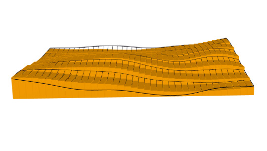
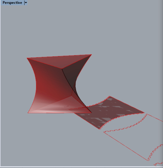
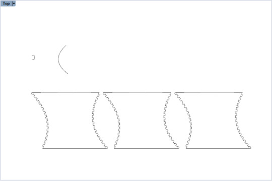
This exercise called upon the team to design and assemble a mold (for eventual concrete casting in exercise 7. part 2) out of 5 foam panels. Using a hot wire cutter attached to a robotic arm, a cut was programmed through Grasshopper and performed lengthwise through each panel to create a new surface condition. Since it was known that all five panels were to be assembled after the respective cuts, the aesthetics and functionality of the assembled piece was an initial charge and intentionality driving the design from the start.
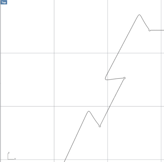
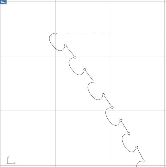
With this in mind, the team decided upon a system of transforming the line through each iteration that would stretch the line in the y-direction (see fig. 3), effectively lowering the frequency of each wave while preserving the amplitude. This was to create a seamless, bunching effect across the five panels. This system allowed for the team to develop an interesting surface condition while respecting the established constraints of the workspace. These constraints included the dimensions of each panel relative to the robotic arm’s range of motion along its six axes, further limited by the dimensions of the hot wire tool (it was later realized that the end-tool dimensions were up for manipulation as well, making it a good point of departure for potential future exploration). The Grasshopper definition had a collision test built-in, which helped to minimize moments at which the path of the lines were at risk of damaging the machinery due to collision of moving arm with self or workspace surfaces.
Ultimately, the final forms ended up producing the desired visual effect. However, fig. 5 depicts the actual paths of lines sent to the robot for cutting. Note that, unlike the conceptualized design in fig. 3, human limits to accuracy within the design program resulted in the cut of 10 unique lines, rather than 5. Though fig. 3 shows that a truly seamless effect would have been possible, the produced forms, in which seams are clearly legible (fig. 5, 6) are successful in that they introduce notions of a Cartesian grid reading back into a form whose lines are otherwise regular, but very organic in their reading.
Furthermore, this process highlights the role of tolerances in design and construction practice. Deplazes notes in reference to the above fig. 6, “...as an example the edge detail for the stair flight and the travertine stair finish, the attitude of the architects with respect to jointing the materials is readily seen.The actual difference in the accuracy of the materials is allowed for, i.e. the different dimensional tolerances govern the treatment of the in situ concrete, which becomes an obvious, protruding edge.” (p. 373) In a way similar to what might be the ‘happy accident’ of slightly misaligned seams in the above foam mold, the designers of the stair went into the design and construction process intending to produce this effect, and therefore intentionally accounting for it (though in this case during in situ construction as opposed to prefabrication using a mold). Deplazes points out the potential for tolerances to be not just a way of allowing a system to remain functional as it undergoes a variety of operations and processes at the hands of many tools and actors, but as another moment of agency and authorship for architects.
Tolerance in building systems is often understood as measurable margins of ‘error’; this exercise highlights that tolerances must be defined in relation to the characteristics of the processes and materials to which it refers. For example, in this prototype building system, the slight misalignment of seam lines was perceived to be a very small margin of error at the hand of the program user (designer). However, the precision of the foam cut at the hands of the robot and a finely tuned wire mechanism (which was manually operated at the right speed and heat to produce a clean, accurate cut) made it so that the programmatically defined lines translated clearly to the final object. However despite this honest translation of the digital file, the formal reading of the exercise remained intact and perhaps enhanced by the human tolerance.
Source for Discussion:
Deplazes, Andrea. Construction Architecture: Materials, Processes, Structures: A Handbook (4th Edition). Berlin: Birkhauser, 2005.
2 notes
·
View notes
Photo


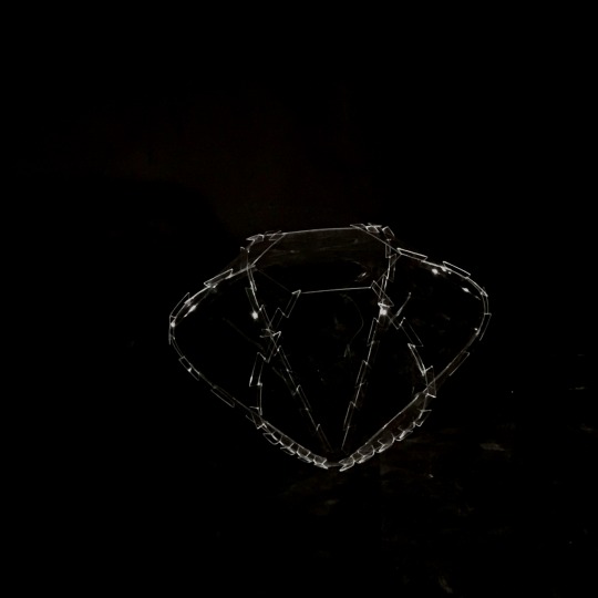
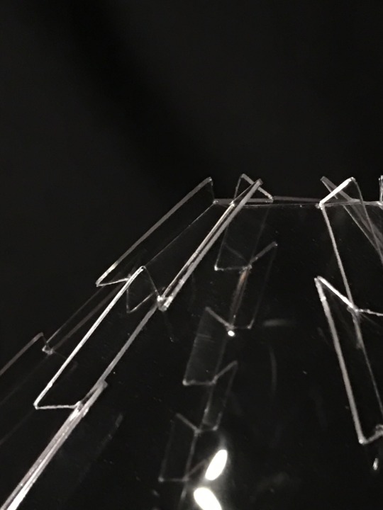
exercise 6 - robotic toolpaths
Work done in collaboration with Annette Chu ‘20 and Halima Matthews ‘21.
location - Princeton University Embodied Computation Lab (ECL)
program - Grasshopper Definition through Rhino
tools - ABB 120 6-axis robotic arm with 6 bulb multicolor LED end-tool; DSLR camera - Wide Angle and Telephoto Lenses
This week’s exercise involved using a robotic arm to trace the path of a line in real space. A camera with extended exposure time was used to document the moving path of the LED light robotic end tool as one complete image. This medium of documentation was interesting in that it allowed for spatio-temporal compression, or a reconfiguration of the exercise-as-process into one as-object. The first two images of the set explore this duality. Post-production work enables the reading of the trace as an abstracted object in fig. 1, as opposed to fig.2, in which tool and workshop are legible as actors in-process. In this way, the photo itself exists is a layer of trace or index beyond the production of the line trace.
A main focus of all three studies was to explore depth through directional manipulation of points on the trace line. This method utilized the primacy of one view (top, front, left, etc.) in relation to the set camera point to preserve the “original” reading of the path. The study curve of a an abstract face (fig. 4 - 6) reads as programmatically defined in the straight-on photo (fig. 1, 2). In fig. 3, an intervention at the point of documentation was made. Throughout the duration of the trace path at the given camera shutter speed (~30 seconds) the zoom was manually adjusted on the lens. Instances or points of the robot’s traced path were documented in relation to the zoom operation, or location of the camera lens in space (moving along a linear axis perpendicular to the aforementioned primary view, rather than in relation to the set plane of a non-moving photo frame). The result is an image in which hyper-distortion of space reveals the hidden relationships of points along the trace, or the three-dimensional actualities of the curves between points that is obscured in the normal view of fig. 1.
This exercise further highlights the autonomy of documentation media as tools or moments of intentionality and intervention in the design process (not just as objective records, speaking to Allen’s points in “Plotting Traces on Process”). Secondly, and more relevant in a building systems context, the image set of fig. 1 - 3 allows for a structural reading of the trace. “In Deplazes’ discussion on space frames, he notes that they ‘consist of delicate linear members’ (Deplazes, 136). In discussing ‘diamonds and diagonals’ Deplazes notes that ‘horizontal loads can be accommodated with a single structure of linear members seemingly without any hierarchy, but equally because the network takes on an ornamental quality’ (Deplazes, 137). These linear members are not dissimilar to the movements of the robot arm, which follow the paths of the curves. The arm moves through each point of the line in a certain order, so each movement contributes in a very specific way to the final produced form. This aligns with the lack of hierarchy that Deplazes mentions. In fig. 1, moments of strong light begin read as junctures at which forces would be concentrated if this line were to exist as a space frame. However, fig. 2 upends understanding of which moments exist as actual joints of the line occupying the same point in space at two moments, and which just appear to do so from the primary perspective. This further complicates ideas of hierarchy and calls into question the true extent of structural need for geometrically repetitive forms in space frames, comparing for example the highly regular rhombi of Herzog and de Mueron’s Prada store in Tokyo, versus the more organically linear members of the columns in Toyo Ito’s Mediathek in Sendai.
The study curve in fig. 7 is less of a precise form but still depicts depth through the use of two colors. The yellow LED light slightly offsets the red, making it appear as a three-dimensional form. The study curve in fig. 8 was supposed to take the shape of a house but the low number of points on the grasshopper definition distorts the image. The LED light image might not show the depth as well, but by looking at the Rhino screenshots you can see the various forms that come out of pulling a few points in different directions.”
(notes adapted from Matthews ‘21 writings on exercise 6)
Source for Discussion:
Stan Allen. “Chapter 3, Plotting traces on process” in Practice: Architecture, Technique and Representation. London: Routledge, 2003. 47–70.
Deplazes, Andrea. Construction Architecture: Materials, Processes, Structures: A Handbook (4th Edition). Berlin: Birkhauser, 2005.
1 note
·
View note
Photo
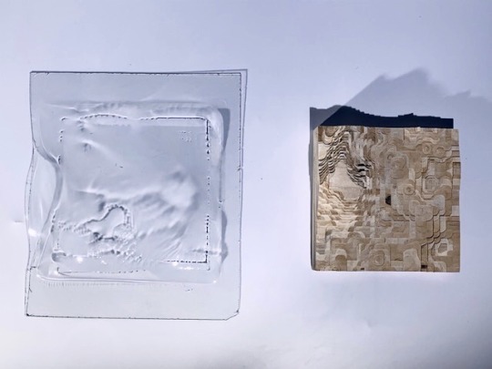
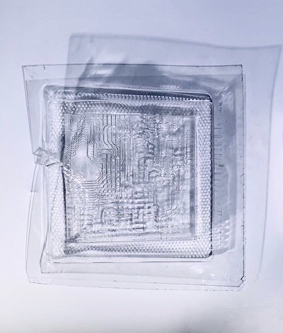
exercise 5. part 2 - solid to surface
Work done in collaboration with Annette Chu ‘20 and Halima Matthews ‘21.
Continuation of exercise 5 (see exercise 5. part 1 - surface to solid ).
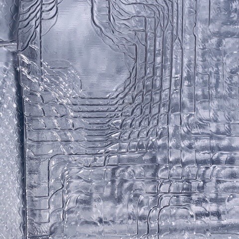
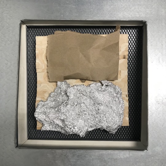
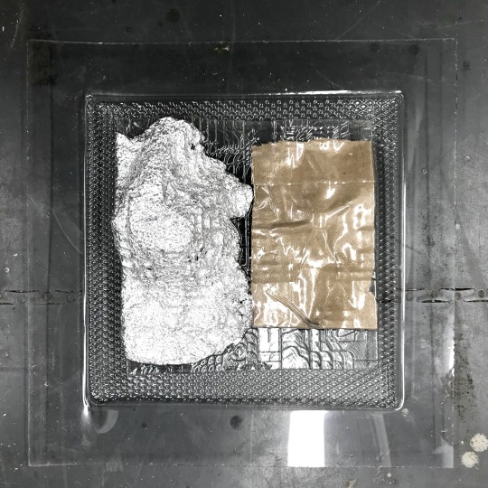
“In part two of this exercise, the task was to use the vacuum former to mold recycled PETG sheets to the milled objects created. First, the milled volume was placed in the center of the vacuum form sheet bed, then it was lowered. The plastic sheet, cut to size, was then placed in the form and heated. At first, the desired heat levels achieved by monitoring the timer through the duration of heat application (approx. 100 seconds), but the plastic was also monitored visually and through touch . Once the plastic was at the correct heat and malleability, the bed with the milled form was pushed up into the plastic sheet, while the plastic sheet was pulled down and taut onto the mill by the vacuum itself.
The images presented show how the plastic was able to capture the details of the milled forms (and how it may not have done so). When additional materials were added (paper bag and tinfoil, fig. 4 - 7) the details of that material were replicated in the vacuum form, hinting at a new legibility of the vacuum formed plastic as a trace of structure (wood cut) and scaffolding (tinfoil and paper bag). Or, even though the tinfoil has a crumpled texture not adherent to any sort of topographical logic, the addition of the foil back onto the abstracted topography allows for a reading of the form as having more fidelity or formal ‘honesty’ about the data from which the object originates.
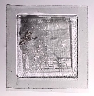
This act of manipulation can be related back to Deplazes’ discussion on plastic and how different materials have different “requirements they have to meet” (Deplazes, 331). There are, of course, limitations in the ways in which plastic can be used, as there are limitations to using any material. The plastic acquired concavity as it was more subject to gravity when hot but it was important to keep it from getting too hot, as too much deformation made it susceptible to tearing or other deformation. Conversely, if the plastic was not hot enough, it was unable to fully capture the textures and shapes of the milled form (fig. 1). Furthermore, issues were encountered in the removal of the plastic from the mill. At any areas on the sides of the mill that protruded out and back in (due to slight error in lamination of the block in exercise 5. part 1), the plastic was too tightly molded around these parts, making removal without cracking of the plastic nearly impossible.
Though the heat-applied vacuum former has arguably been the least technologically complex tool encountered so far in these studies, there are still many points of design intervention that can occur. In addition to choices about material and form itself, duration and intensity of heat application and vacuuming are both variables which allow for greater authorship. Furthermore, these variables operate under temporal conditions, in that their effects are relational to each other and the material based on the time that passes (or doesn't) between steps as well. This high tolerance characteristic of the tool requires more direct operational skill from the user than those tools which are data-driven and operate based on systems of points.
(notes adapted from Matthews ‘21 writings on exercise 5 part 2)
Source for Discussion:
Deplazes, Andrea. Construction Architecture: Materials, Processes, Structures: A Handbook (4th Edition). Berlin: Birkhauser, 2005.
1 note
·
View note
Photo


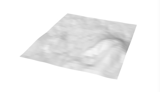


exercise 5. part 1 - surface to solid
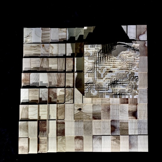
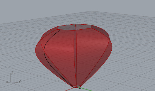
In this exercise, topographical data points were downloaded from the NASA Shuttle Radar Topography Mission (SRTM) database and translated into a digital surface. Then, this surface was put into a grasshopper definition which extruded the surface from a given plane in order to generate a solid. This solid was milled on the CNC router through a materially reductive method, in which an instruction set consisting of coordinates (generated through RhinoCAM) informed the mill’s path to cut away material from the solid block of 20″x 20″x 3″ laminated wood. This study prompts attentiveness toward the implications of relative scale throughout all stages of design and fabrication processes, both how scale functions as a generator of unknown variability and as design tool.
selection of topography - scale of earth v. scale of the product, earth’s surface is actually very flat relative to size of sphere on which it sits. This flatness reads even at the scale of a single latitude-longitude swatch of extracted data points (NASA Shuttle Radar Topography Mission). In order to combat this scale and define an area in the lat-long that had appropriately variable elevation, the area extracted for the surface had to be reduced to 1:100 of the original area.
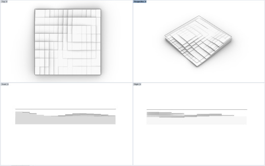
adjustment of parameters of gh determined solid - once the data points had been translated into a surface using the first grasshopper (gh) definition, the baked surface that came as a result was input into the new “chunky surface” definition in order to generate the solid. At this point, various adjustments to parameters within the gh definition such as min/max count, aspect ratio, or even a surface rebuild (not within the gh definition, but rather command within rhino onto the surface) all yielded variable conditions of the base unit, or the smallest flat element within the larger topography. Object 1 has many large, rectangular units as a result of a long series of arbitrary aesthetic adjustments, which equates to lower fidelity to the variability within the original surface and a more abstracted reading. Object 2 was not subjected to any parameter changes, and therefore exhibited much smaller and more square elementary units that were able to accommodate the true topography more accurately.
translation render-to-mill - in this final step, the implications of tool capabilities and limitations were made very apparent. On object 1, the size of the milled object, though it looks much less complex and of lower variability than object 2, took much longer to mill (3 hours opposed to 30 min) due to the fact that it was 2.5x the length and width of object 2. This is of practical consideration when constructing multi-step and piece models in which material efficiency/cost and time/labor costs are of relevance. In fact, it was due to time/labor constraints that the decision was made to mill object 2 at the smaller size. This resulted in some movement of the block during the milling process, as the shear forces were strong enough to begin to dislodge the form from its constraints (small blocks visible in fig. 8). Additionally, for object 1, the angle of approach of the end mill was set to 45 degrees for the finishing portion of the job (versus 30 degrees for object 2). This angle, accompanied by the low relative depth of each unit to those surrounding compared to its surface area might have been the cause for some of the shearing forces that delaminated some of the object’s top layers (visible in fig. 9, large flat space in bottom right corner of object 1). On the other hand, the large elementary units paired well with the .5 inch end-mill, in that the corner moments, though still rounded in actuality, look very angular at the scale of the unit whole. In contrast, on object 2, due to the fact that the elementary unit was about .5″x.5″, the reading of this corner bevel resulted in a much more jagged and organic looking finish. The scalloping and sometimes fully circular moments on the final product inadvertently begin to allude to the mountainous nature from which this solid was derived, all due to a matter of relative scales.
The milled objects hold some connection to the following systems example in Deplazes: Shin Takasuga’s Railway Sleeper House. “The universal utilisation of one single type of construction element for the whole structure – walls, floors, columns, roof structure, the built-in furniture too” (106) of the house allows it to read as a sort of natural extension of the forested topography of Miyake island, on which it is situated. Further blurring lines between landscape and building, “in the Railway SleeperHouse we can identify a subtractive design principle: the rooms seem to have been hacked out of a closed, cruciform stack with a rigid outer shape”. Similarly, the raw materials rely on the subtractive quality of the milling process to reveal the varied 'stacked’ surface conditions. One might even begin to reimagine the above exercise objects to some human scale, as containing qualities among its ridges and folds, where ridges begin to read as semi-hollow surfaces and platforms with habitable internal structure.
Source for Discussion:
Andrea Deplazes (ed.) “Materials - Modules: Timber, The Threads of the Net” in Constructing Architecture: Materials, Processes, Structures: A Handbook. Berlin: Birkhauser, 2005. pp. 106 -112.
3 notes
·
View notes
Photo
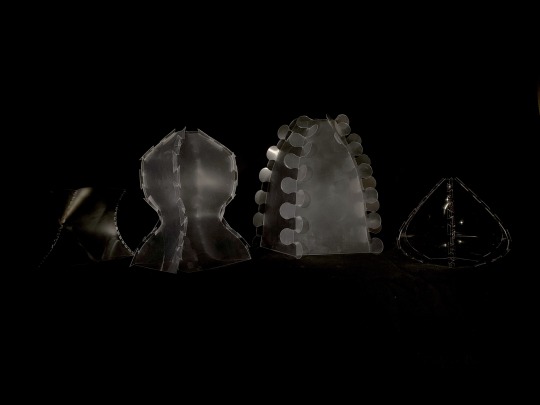


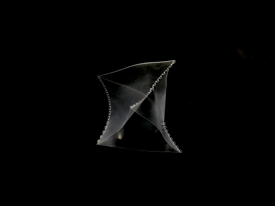
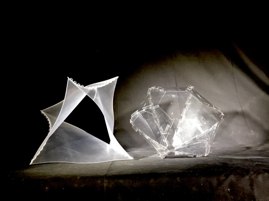
exercise 4. part 2 - a developable surface in the process of fabrication
In week 2, the focus was on fabrication/assemblage, and the technical implications of translation from digital render to physical object. Deliverables were produced by project partners Tatijana Stewart and Halima Matthews.
“…Plastic, sublimated as a movement, hardly exists as a substance... It has to be content with a neutral quality of substance: resistance...” (Deplazes, 150)
This quality of resistance is what enables the built forms to hold their shape. The following observations were made during development of the four final prototypes (fig. 1):
1. Tabs have structural purpose—to resist material forces, especially at points of greatest curvature. Do the tabs allow for a tight seam (objects 1, 2, and 4) or does the object remain loose at its joints (object 3)? Note: looser seams allow for easier dis-/assemblage, while the reverse is true for tighter seams
2. Tabs have aesthetic value—size, number and shape of tabs all must be considered. Should tabs keep a low profile against the object or be highly visible? Should they be in synergy with formal expression of the object (object 2), or in contrast (object 1)? Should they be sized only for functionality (object 4), or should their size contribute to how the object is read (object 3)?
3. Due to the uniform nature of the parts used to construct these objects (identical panels), adjustments in object shape and volume are readily possible through the addition/removal of panels. This makes the objects modular, in a sense. As panels are added, more stress is put on the curved portions of the object, as the addition of material pushes these curves more and more into the maximal shape.
4. Fig.10 highlights varying opacities among prototypes. This was achieved through removal of thin plastic protective film on the actual plastic material. Further possibilities include utilizing the ZÜND to etch or draw on the panels.
5. In object 1, the shape of the tabs worked so that, based on material thickness (1/32″) and size of the circles at the inner tab corners (see discussion of previous post, exercise 4. part 1), the tabs were able to slip in easily but held a tight seam once assembled. Of the four prototypes, this tab profile seems optimal.
6. Further Possibilities: object 1 utilized a profile curve which existed three-dimensionally. As such, movement manifests within the formal properties of the object (fig. 10). However, there are limits to the profile curve within the constraints of grasshopper instructions used for this exercise. In order to reach a higher order of complexity of shapes, the instructions would need a range of design intention-specific adjustments (i.e. to enable tabs on more than 2 sides, or a rule for tab number/spacing independent of profile curve length).
Source for Discussion:
Andrea Deplazes (ed.) “Plastic on the Threshold of Architecture” in Constructing Architecture: Materials, Processes, Structures: A Handbook. Berlin: Birkhauser, 2005. pp. 150,159 -166.
1 note
·
View note
Photo
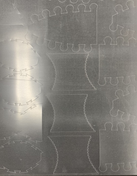
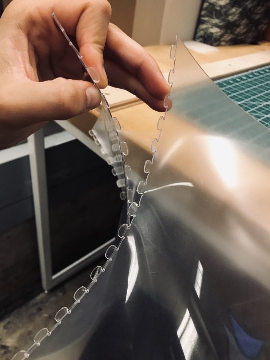
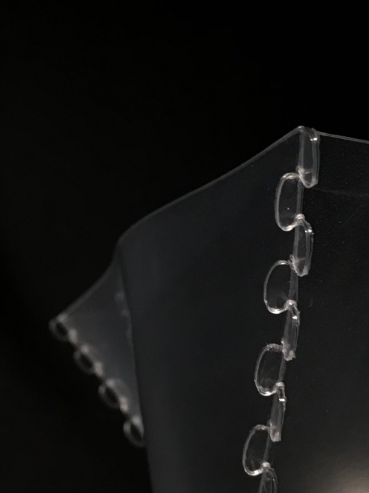
exercise 4. part 1 - a developable surface in the process of fabrication
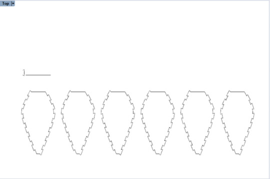
In this two-week exercise, a simple digital fabrication process is explored, from design generation to prototype construction. The end goal is to assemble a 3D object through the fabrication of interlocking 2D parts cut from a sheet of material. In order for the translation from digital 3D (fig. 1, fig. 4) to fabricated 2D (fig. 2, fig. 5) to fabricated 3D (assemblage of parts) to be successful, special consideration must be given to the details of the design. To be specific, tab design requires precision, because the tabs lining the edges of each element are the only source of support/jointing for the object. It is important that the tabs are designed to stay interlocking. This is tectonically reinforced through the shape of the tab. In order to create a more seamless joint, the size of the holes which account for material thickness must be in relation to the material itself, the overall shape of the object (and the varying forces across the its surfaces) and the way in which the tabs function due to their shape.
a note on material - Though the design has not yet reached fabrication stage, it is important to note how the material properties will likely affect the design. This object will be constructed using a plastic material some millimeters thick. The ZUND, which will be used to cut the material, will cut the material with high precision. The plastic itself is of a sort that it maintains its flat shape, and forces within the material will resist action that tries to force the material out of this flat state. That being said, the material exhibits some plasticity which allows for it to be bent and curved into various shapes. In looking to the Deplazes Handbook, it becomes clear that the relevant benefit of plastic in the case of this exercise is the high variability in material properties among its different types. A point of departure for other variations of this fabrication study may be to explore how various plastics produce differing results under the conditions and parameters defined in the grasshopper model in which this exercise is based.
Source for Discussion:
Andrea Deplazes (ed.) “Plastic on the Threshold of Architecture” in Constructing Architecture: Materials, Processes, Structures: A Handbook. Berlin: Birkhauser, 2005. pp. 159-166.
1 note
·
View note
Photo
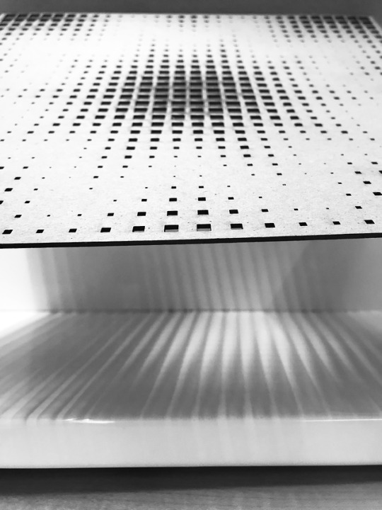
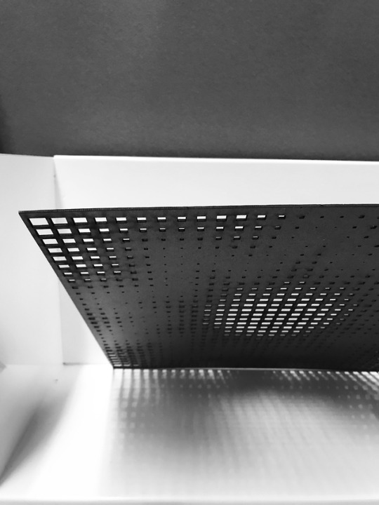
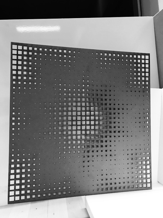
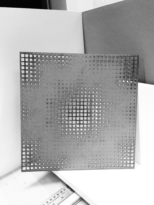
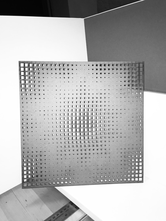
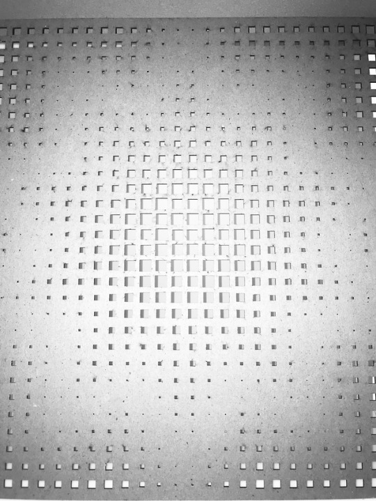
exercise 3 - a responsive surface
elements// a surface, a grid, a curve
relationships// grid on surface guides perforations. distance from curve determines magnitude of grid element.
process// grasshopper through rhino, laser cut
generating new forms// adjust: surface size, path of curve, span of grid elements in x direction and y
“It is only the openings in the walls that create a spatial reference with the outside world.” (Deplazes, 319). Here is the wall. It is of some thickness, expressed not by the surface itself, but rather within the depths of each void. The control of light: it is interplay between that which which passes through the object and that which does not. Different light conditions produce different readings of the constructed surface. Here, we understand the planar surface as both barrier and threshold. The curve element is only legible through the voids which depend upon it to guide their form.
material//chipboard 12″ x 12″
Source for Discussion:
Andrea Deplazes (ed.) “Morphological Deductions” in Constructing Architecture: Materials, Processes, Structures: A Handbook. Berlin: Birkhauser, 2005. pp. 220, 319.
1 note
·
View note
Photo
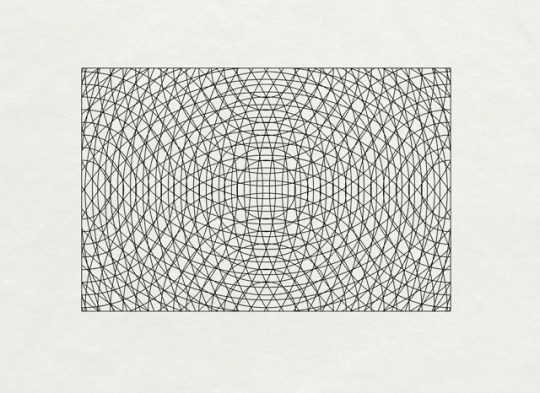
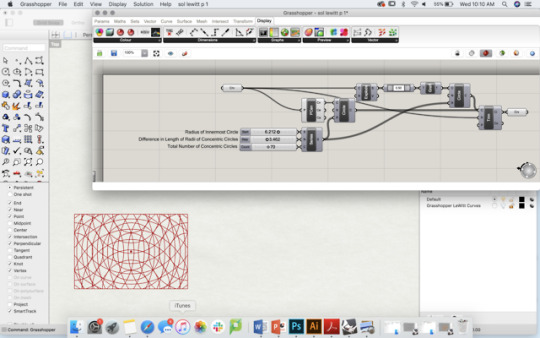
exercise 2 - algorithmic reproduction of Sol LeWitt’s Wall Drawing 138
In Wall Drawing 138, Sol LeWitt introduced a visual vocabulary of "Circles and arcs drawn from the midpoints of four sides.” (ACG 59) July 1972
This exercise is an exploration of the algorithmic processes which generate various iterations of conditions within the field, in order to achieve the above-stated parameters. Key to the process itself is intentionality about which elements are being manipulated, and in which ways. In this study, the 5 origin points of circles (arcs) were the center of the initial field(rectangle) and the midpoints of the four plane edges (Fig. 1). To start, a series of functions were applied to the rectangle, using Grasshopper. In order to generate variable forms that all met the prescribed initial conditions, number sliders were added to the panel which controlled the a) radius of the most central circle (S-start) , b) the distance between each concentric circle in a series (N- Step) and c) the total number of circles radiating outward from any point (C - Count). By making all three of these conditions variable, an infinite number of unique results are achievable.
The context of LeWitt’s original is a large gallery space, in which the ‘rectangular’ frame of the field is actually defined by the squarish wall on which the artwork exists. In Deplazes Constructing Architecture, a note on “The Opening as a transparent wall” (p. 220) sheds a new light on how we may understand the relationship between the generated lines and the prescribed field of Wall Drawing 138. We can perceive the lines as establishing a threshold between observer and wall, then the wall itself is not a boundary, but rather a new inhabitable space in the mind’s eye. This effect is similar to that achieved through a floor-to-ceiling window which spans from wall to wall. The window is the field, and the mullions exist as linear elements which guide our reading of the threshold itself, and the space beyond.
Source for Discussion:
Andrea Deplazes (ed.) “Materials - Modules” in Constructing Architecture: Materials, Processes, Structures: A Handbook. Berlin: Birkhauser, 2005. pp. 220, 306-307.
0 notes
Photo
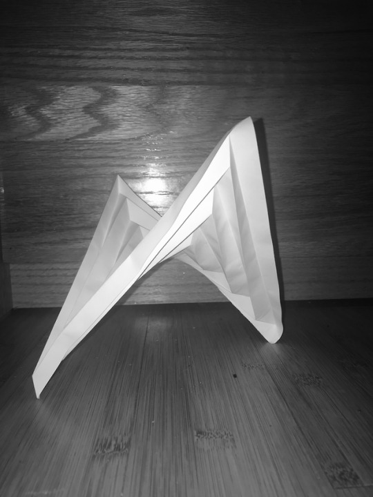
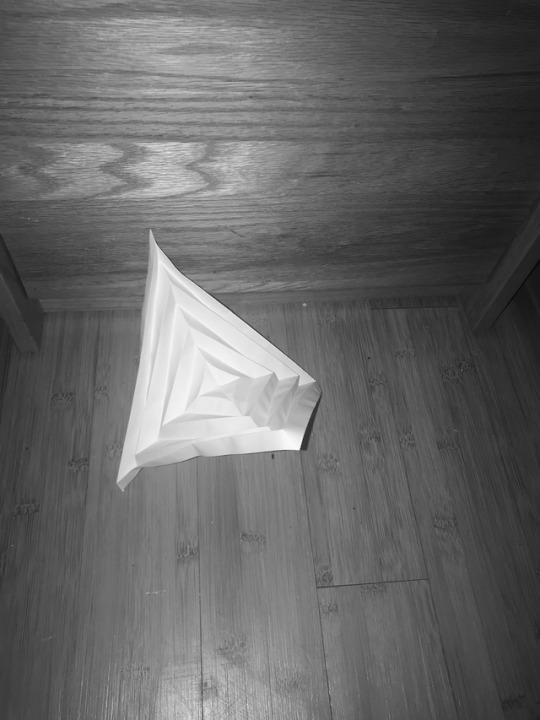
exercise 1 - folding a square paper into a hyperbolic paraboloid
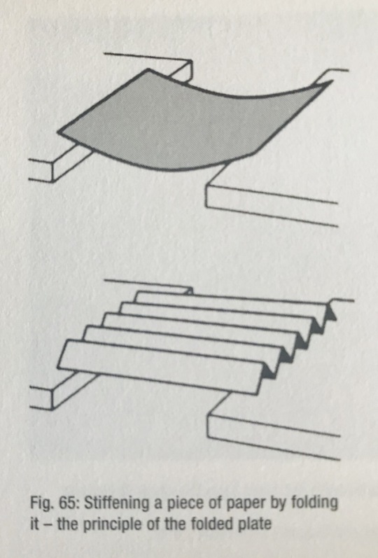
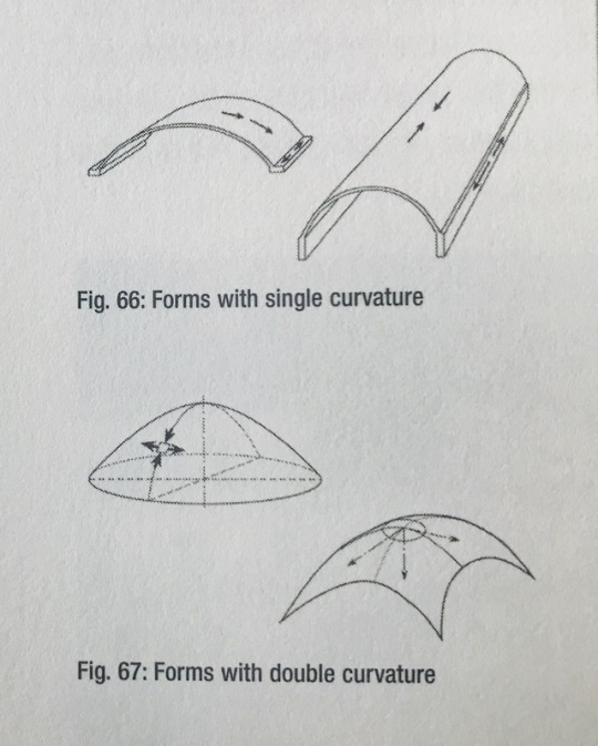
This conditions of this paper structure which give it strength and form are its anticlastic Gaussian curvature (double curvature in which the two rules of parabolic curves are extending in opposite directions and therefore are in tension with each other - different from the picture fig.67 (Deplazes, p. 76) showing synclastic curvature, where the two curves extend in the same direction downward) and its doubly ruled (perpendicular) folds. Through this redistribution of forces along the folded edges, the paper obtains a structural shape.
Source for Figures 65 and 67:
Andrea Deplazes (ed.) “Materials - Modules” in Constructing Architecture: Materials, Processes, Structures: A Handbook. Berlin: Birkhauser, 2005.
2 notes
·
View notes