#RF Propagation Modeling
Explore tagged Tumblr posts
Visit Tumblr Blog
Explore Tumblr blogs with no restrictions, modern design and the best experience.
Last Seen Tumblr Blogs


Fun Fact
Women make up for the other 50% of Tumblr’s audience.
Text
Location Intelligence Sri Lanka
Transform Your Business with Location Intelligence: Unlock the Power of Geospatial Insights
Location Intelligence empowers organizations to make data-driven decisions by providing actionable insights derived from geospatial data. By integrating location-based analytics into your operational processes, you can enhance efficiency, improve customer engagement, and drive strategic growth.
Elevate Your Decision-Making with Advanced Geospatial Analytics and Insights
In an increasingly complex business landscape, organizations need the ability to analyze and leverage location-based data effectively. Location Intelligence combines advanced mapping, spatial analysis, and data visualization tools to enable businesses to uncover critical insights that inform strategic decisions. Whether you’re optimizing supply chains, enhancing customer targeting, or improving operational efficiency, Location Intelligence provides the tools you need to succeed.
This solution integrates seamlessly with existing data sources, allowing for a holistic view of your operations. By harnessing the power of geospatial analytics, businesses can identify trends, forecast demand, and streamline processes, leading to improved outcomes across various sectors, including retail, logistics, urban planning, and emergency management.
Why Location Intelligence?
Unmatched Analytical Power
Location Intelligence enables advanced analytics that reveals patterns and trends in your data, allowing you to identify opportunities and risks in real-time. By leveraging spatial data, businesses can uncover hidden insights that lead to more informed strategic decisions.
Actionable Insights
Turn complex geospatial data into actionable insights with intuitive visualization tools that help stakeholders grasp key information quickly and make informed decisions. With clear visual representations of data, teams can collaborate more effectively and align their strategies for optimal results.
Cost Optimization
Identify inefficiencies in your operations, such as excess inventory or underutilized assets, and leverage insights to optimize resource allocation and reduce costs. This strategic approach to resource management not only saves money but also enhances overall operational efficiency.
Seamless Data Integration
Effortlessly integrate diverse datasets from various sources, such as CRM systems, GIS platforms, and business intelligence tools, for a comprehensive view of your operations. This holistic perspective enhances your understanding of market dynamics and customer behavior, enabling more effective decision-making.
Enhanced Customer Targeting
Utilize location data to understand customer behavior and preferences, enabling personalized marketing strategies that improve engagement and retention. By targeting customers based on their geographic profiles, businesses can create tailored offerings that resonate more deeply with their audience.
Scalable Solution
Designed to grow with your organization, Location Intelligence can be tailored to meet the needs of businesses of all sizes, from local enterprises to global corporations. As your business evolves, the solution adapts, ensuring you always have the analytical capabilities required to stay competitive.
What the Users Say
Location Intelligence Features
Advanced Geospatial Analytics
Harness the power of sophisticated analytics tools to explore spatial relationships within your data and derive actionable insights that drive business performance.
Customizable Dashboards
Create tailored dashboards that highlight the metrics and KPIs most relevant to your business, ensuring that stakeholders have immediate access to the insights they need.
Multi-Source Data Aggregation
Integrate data from various internal and external sources, such as social media, CRM, and market research, to create a comprehensive view of your business environment.
Interactive Mapping Tools
Utilize user-friendly mapping interfaces to visualize complex data sets in a clear, intuitive manner, making it easy for teams to identify trends and opportunities.
Geofencing Capabilities
Implement geofencing to track customer movements and behaviors in real-time, allowing for targeted marketing efforts and improved operational strategies.
Collaboration Tools
Facilitate teamwork and communication across departments with built-in collaboration features, enabling teams to share insights and strategies effortlessly.
Real-Time Data Integration
Access and analyze real-time data feeds from various sources, enabling quick responses to changing conditions and informed decision-making.
Predictive Analytics
Leverage machine learning algorithms to forecast trends and customer behavior, empowering proactive decision-making that aligns with market dynamics.
Mobile Access
Access location intelligence on-the-go with mobile-friendly interfaces, ensuring that decision-makers have critical data at their fingertips wherever they are.
Key Facts
01.
Location Intelligence provides access to vast datasets encompassing geographic information from all around the world.
02.
Continuously updated data ensures that you are working with the most accurate and relevant information available.
03.
Backed by expert support and resources to help you implement and maximize the value of location intelligence in your operations.
04.
Designed for cloud integration, allowing for scalable deployment and easy access across your organization.
05.
Built with the user in mind, Location Intelligence features intuitive interfaces that promote ease of use and quick adoption.
06.
Offers pre-configured templates tailored for specific industries, making it easier for businesses to get started quickly.
07.
Ensures that your data is protected with robust security protocols, maintaining compliance with industry regulations.
08.
Fully compatible with popular GIS tools and other software applications, enhancing your existing data ecosystem.
Contact us
Get in Touch with us
Location
7 Temasek Boulevard, #12-07, Suntec Tower One, Singapore 038987
Email Address
Phone Number
+65 6428 6222
#Location Intelligence#Real‑Time GIS#Geospatial Analytics#Spatial Data Visualization#Emergency Response GIS#Urban Planning GIS#Telecom Network Planning#RF Propagation Modeling
0 notes
Text
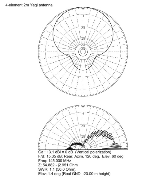
4-Element Yagi antenna for the 2m band
This blog post discusses the engineering design, construction, and performance evaluation of a 4-element Yagi-Uda antenna specifically optimized for the 2-meter amateur radio band, focusing on the frequency range of 144MHz to 145.5MHz. The project was initiated to establish strong and reliable communication with distant VHF repeaters of the RSSL (Radio Society of Sri Lanka), which are located approximately 58km and 96km from my location.

The primary objective was to develop a high-gain, directional antenna with a superior front-to-back ratio. This directionality is essential for maximizing signal capture from the desired repeater while minimizing interference and noise from unwanted directions, ultimately improving the SNR and the quality of the communication link.
VHF communication at these distances typically relies on line-of-sight propagation, making antenna gain a critical factor in overcoming path loss and achieving reliable signal levels.

The antenna design was carried out using MMANA-GAL, a well-known and validated software suite based on the Method of Moments (MoM) for antenna analysis. While MoM simulations require significant computational resources, they deliver accurate predictions of antenna performance. This is achieved by breaking down the antenna structure into small segments and solving Maxwell's equations to determine the current distribution. This approach enables precise modeling of antenna impedance, radiation patterns, gain, and front-to-back ratio.
Key design parameters were iteratively optimized within MMANA-GAL to achieve the desired performance:
Target Frequency Band: 144MHz - 145.5MHz, encompassing the primary 2m amateur band frequencies.
Characteristic Impedance: 50Ω, to ensure impedance matching with standard RG-58 coaxial transmission line and transceiver equipment, minimizing reflected power and maximizing power transfer to the antenna.
Front-to-Back Ratio Optimization: Aiming for a high front-to-back ratio to minimize reception from the rear hemisphere, reducing interference and improving signal clarity, especially in noisy RF environments.
SWR Minimization: Achieving a VSWR as close to 1:1 as possible across the target frequency band. Low VSWR indicates efficient impedance matching and minimal power reflection back to the transmitter.
The simulation process involved adjusting the lengths of the elements and the spacing between them for the reflector, driven element, and directors of the Yagi antenna. This antenna operates on the principles of constructive and destructive interference of electromagnetic waves. The reflector, positioned behind the driven element, reflects waves forward, while the directors, located in front of the driven element, help to focus the radiated energy toward the main lobe. This arrangement increases both the forward gain and directivity of the antenna.

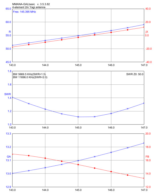
The optimized design, after multiple simulation iterations in MMANA-GAL, predicted the following performance metrics:
Simulated Gain: 13.1dBi. This represents a significant gain increase over a dipole antenna (approximately 2.15dBi) and translates to a substantial improvement in signal strength.
Simulated Front-to-Back Ratio: 15.35dB. This indicates that the power radiated in the forward direction is over 15dB stronger than in the backward direction, providing good directivity and rejection of rearward signals.
Simulated Input Impedance: Close to 50Ω across the 144MHz - 145.5 MHz band, ensuring a good match to standard 50Ω transmission lines.
The construction of the antenna focused on durability, lightweight design, weather resistance, and good electrical conductivity, all while keeping costs reasonable. We used 10mm diameter aluminum alloy tubes sourced from Lanka Aluminum. This diameter was selected because it is commonly available at many aluminum stores.
For the boom, we use a rigid 19.05mm (3/4 inch) square aluminum box bar, also sourced from Lanka Aluminum. This material is made from a similar aluminum alloy to ensure structural integrity and to serve as a common ground plane for the parasitic elements. The square profile enhances torsional stiffness compared to a round boom.
To effectively secure the components, we use 10mm ABS element holders. These holders are commonly utilized here to construct VHF/UHF TV antennas. Both the plastic holders and 10mm end caps are sourced from Kumarasinghe Radio.

The Polychrome junction box, measuring 85×85×50 mm and designed for outdoor use, is waterproof with an IP55 rating. This rating indicates that the box provides protection against dust ingress (although some dust may enter, it won’t cause harm) and shields against water jets from any direction. This makes it an essential choice for long-term outdoor deployment, ensuring the critical dipole feedpoint remains protected.
We used corrosion-resistant M3 stainless steel nuts, bolts, and washers to secure all elements and the IP box.
Precise assembly is crucial for achieving the intended performance of a Yagi antenna. All elements, except for the driven dipole, were directly and electrically bonded to the aluminum boom. This is a standard practice for Yagi antennas, as it utilizes the boom as a common ground, simplifying construction. Electrical connections were established using M3 stainless steel bolts that passed through pre-drilled holes in the aluminum tubes and boom, ensuring reliable electrical contact. The element holders provided mechanical support and maintained precise spacing between the elements, as well as a 90° angle with the boom, in accordance with the design specifications from MMANA-GAL.

The IP55 box containing the dipole was securely mounted to the underside of the aluminum boom using M3 stainless steel fasteners. To ensure consistent height with other elements, we used a strip of 10mm acrylic sheet.
Antenna VSWR and input impedance were measured across the frequency range of 144MHz - 145.5MHz using a VNA. The measured SWR of 1.1 at 145.025MHz confirms excellent impedance matching at the desired operating frequency. A Smith chart, generated by the VNA, visually represented the antenna's impedance characteristics throughout the band. It demonstrated that the impedance remained close to the target of 50Ω, indicating a broadband match across the intended operating frequencies.

The antenna was deployed at the designated operating location and oriented towards the target RSSL VHF repeaters. A subjective performance evaluation was conducted by attempting communication with the repeaters at distances of 58km (Yatiyanthota) and 96km (Piduruthalagala).
Reports from repeater users consistently indicated an S9+ signal strength, showing a significant improvement in reception when compared to a baseline mobile whip antenna.
You can find the complete design of this antenna, including all dimensions, in the PDF linked here. The Fusion 360 design file for the antenna is also available here. Additionally, the MMANA-GAL design file (in .mma format) can be downloaded from this link.
0 notes
Text
Enhancing Wireless Network Planning: Site Selection and Propagation Modeling with Advanced tools
Optimizing wireless network deployment requires precision in site selection and RF propagation modeling. 📡 Advanced tools like MapInfo Pro, Spectrum Spatial Analyst, and 3D Scene Viewer help network planners analyze terrain, population density, signal coverage, and interference to ensure seamless connectivity. From viewshed analysis to capacity planning and interference management, leveraging data-driven insights leads to stronger, more reliable networks. 🔍 Discover how Advintek Geoscience empowers smarter network planning with cutting-edge geospatial solutions.
0 notes
Text
Understanding Garage Door Remote Control Range: Key Factors and Selection Tips for Optimal Performance
Garage door remote controls are an essential component of modern home automation systems. Their primary function is to provide convenience and security, especially when users need to operate the garage door from outside or at a distance. The effective operating range of a remote control is crucial as it determines the reliability and stability of the device at various distances. Thus, selecting the right remote control is key to ensuring smooth operation of the garage door system.
This article will explore the effective operating range of garage door remote controls, including the factors affecting this range, comparisons of different remote control models, and how to choose a remote control that meets your needs.
1. Basic Working Principle of Remote Controls
1.1 Signal Transmission and Reception
Garage door remote controls typically use radio frequency (RF) technology to send wireless signals to a receiver, controlling the garage door’s opening and closing functions. When a button on the remote control is pressed, it transmits a signal at a specific frequency. The receiver, upon receiving this signal, performs the desired action, such as opening or closing the door.
1.2 Definition of Signal Range
The effective operating range of a remote control refers to the maximum distance at which the remote can reliably transmit a signal. This range is influenced by several factors, including the remote's transmission power, the receiver's sensitivity, and environmental conditions.
2. Factors Affecting Remote Control Range
2.1 Transmission Power
The transmission power of a remote control is one of the main factors determining its effective operating range. Higher transmission power allows the signal to travel farther, maintaining reliable communication over longer distances and reducing the likelihood of signal loss.
2.2 Receiver Sensitivity
Receiver sensitivity also plays a crucial role in the operating range of a remote control. A receiver with high sensitivity can detect weaker signals, enabling stable operation even at greater distances. The design and quality of the receiver directly impact its ability to reliably receive signals.
2.3 Signal Frequency
Remote controls typically operate on different radio frequencies (such as 315 MHz, 433 MHz, etc.). The frequency used can affect the signal’s penetration ability and range. Lower frequencies generally have better penetration capabilities, while higher frequencies may be more susceptible to interference.
2.4 Environmental Factors
Environmental factors significantly impact the effective operating range of remote controls. Common sources of interference include:
Obstacles: Walls, buildings, and furniture can block or weaken the signal.
Interference Signals: Other electronic devices (such as wireless networks and Bluetooth devices) may emit signals on similar frequencies, causing interference.
Weather Conditions: Extreme weather conditions (such as strong winds or thunderstorms) can affect signal propagation.
2.5 Remote Control Design
The design of the remote control itself affects its operating range. High-quality remote controls often feature better signal transmission and reception designs, which can enhance both range and stability. For example, using high-gain antennas and optimized circuit designs can improve signal strength and reliability.
3. Comparison of Different Types of Remote Controls
3.1 Fixed Code Remote Controls
Fixed code remote controls use a static radio signal for communication. While they are typically more affordable, they offer lower security and may be more susceptible to interference. The effective operating range of fixed code remote controls is generally shorter, usually between 10 to 30 meters.
3.2 Rolling Code Remote Controls
Rolling code remote controls use a dynamic encoding method to enhance security. Each time the remote is used, the signal code changes automatically, reducing the risk of signal interception and duplication. Rolling code remote controls usually offer a longer operating range, typically between 30 to 60 meters.
3.3 Encrypted Remote Controls
Encrypted remote controls utilize advanced encryption techniques to protect the signal's security. These remote controls not only improve security but also enhance signal stability. Their effective operating range can exceed 60 meters, making them suitable for scenarios requiring high security.
4. How to Choose the Right Remote Control
4.1 Assess Your Actual Needs
When selecting a remote control, first assess your actual needs. For example, if the garage door is located far from the main house, you may need a remote control with a longer effective operating range. If the garage door is in a complex environment, choosing a remote control with strong anti-interference capabilities is important.
4.2 Choose High-Quality Products
Selecting a high-quality remote control brand and product is essential for ensuring range and stability. Opt for reputable brands that use advanced technology and strict quality control measures to guarantee the performance and reliability of their products.
4.3 Understand Environmental Conditions
Consider the installation environment when choosing a remote control. If there are many obstacles or sources of interference, you may need a remote control with stronger signal penetration or additional signal enhancement equipment.
4.4 Testing and Adjustment
Testing and adjusting the remote control in real-world conditions is an effective way to ensure its operating range. By testing the remote at different distances, you can assess its performance and make necessary adjustments to optimize its effectiveness.
5. Practical Case Studies
5.1 Residential Applications
In residential settings, the effective operating range of a garage door remote control typically needs to be between 30 to 50 meters. Consider the distance between the garage door and the main house, as well as potential obstacles. Choosing a suitable remote control ensures smooth operation even from a distance.
5.2 Commercial Applications
In commercial settings, such as large parking lots or commercial complexes, a longer remote control range may be required. Such applications often involve greater distances and more complex environments, making high-performance remote controls and signal enhancement equipment crucial.
5.3 Industrial Applications
In industrial environments, garage door remote controls must offer high anti-interference capabilities and extended operating ranges. Industrial settings may have significant electromagnetic interference, so selecting remote controls with strong signal stability and anti-interference designs is essential.
6. Conclusion
The effective operating range of a garage door remote control is a key consideration for users when selecting a remote. By understanding the factors that influence operating range, including transmission power, receiver sensitivity, signal frequency, environmental conditions, and remote control design, users can choose the remote that best meets their needs. Whether for residential, commercial, or industrial applications, selecting the right remote control ensures the stability and convenience of the garage door system, enhancing the overall user experience.
0 notes
Text
Global Top 7 Companies Accounted for 53% of total Military Submarine Photonics Mast and Antenna market (QYResearch, 2021)
A submarine is a naval platform that can stay underwater for an extended period to carry out missions, both offensive and defensive. It is a complex platform that includes multiple components. As radio waves cannot propagate in water, communication with submarines is difficult. To overcome this issue, submarines are being installed with antennas that can be raised above the water surface level, and employ ordinary radio transmissions for communication.

According to the new market research report “Global Military Submarine Photonics Mast and Antenna Market Report 2023-2029”, published by QYResearch, the global Military Submarine Photonics Mast and Antenna market size is projected to reach USD 0.7 billion by 2029, at a CAGR of 5.7% during the forecast period.
Figure. Global Military Submarine Photonics Mast and Antenna Market Size (US$ Million), 2018-2029

Figure. Global Military Submarine Photonics Mast and Antenna Top 7 Players Ranking and Market Share (Ranking is based on the revenue of 2022, continually updated)

The global key manufacturers of Military Submarine Photonics Mast and Antenna include Thales, L3Harris Technologies, Safran, Hensoldt, Comrod Communication AS, etc. In 2021, the global top four players had a share approximately 53.0% in terms of revenue.
About QYResearch
QYResearch founded in California, USA in 2007.It is a leading global market research and consulting company. With over 16 years’ experience and professional research team in various cities over the world QY Research focuses on management consulting, database and seminar services, IPO consulting, industry chain research and customized research to help our clients in providing non-linear revenue model and make them successful. We are globally recognized for our expansive portfolio of services, good corporate citizenship, and our strong commitment to sustainability. Up to now, we have cooperated with more than 60,000 clients across five continents. Let’s work closely with you and build a bold and better future.
QYResearch is a world-renowned large-scale consulting company. The industry covers various high-tech industry chain market segments, spanning the semiconductor industry chain (semiconductor equipment and parts, semiconductor materials, ICs, Foundry, packaging and testing, discrete devices, sensors, optoelectronic devices), photovoltaic industry chain (equipment, cells, modules, auxiliary material brackets, inverters, power station terminals), new energy automobile industry chain (batteries and materials, auto parts, batteries, motors, electronic control, automotive semiconductors, etc.), communication industry chain (communication system equipment, terminal equipment, electronic components, RF front-end, optical modules, 4G/5G/6G, broadband, IoT, digital economy, AI), advanced materials industry Chain (metal materials, polymer materials, ceramic materials, nano materials, etc.), machinery manufacturing industry chain (CNC machine tools, construction machinery, electrical machinery, 3C automation, industrial robots, lasers, industrial control, drones), food, beverages and pharmaceuticals, medical equipment, agriculture, etc.
0 notes
Text
Electrical strength metering
Create Performance-Optimized Reference Signals – Create calibrated alerts, confirmed through Keysight, that signal generator in uae conform to industry requirements to help beautify the characterization and verification of your gadgets

Validate Component, Transmitter, and Receiver Testing – Easily create and playback custom designed waveforms for issue testing with sincerely distortion–free test signals
Ensure Designs Meet Latest Standards – Trust that the indicators you generate are modern-day with the state-of-the-art rising technologies
Speed Signal Creation and Reduce Simulation Time – Accelerate your checking out with graphical tree–fashion navigation
Go past math-primarily based modeling with a entire RF-aware design workflow, plus many years of Keysight dimension science in RF instrumentation, equipped for any gadget architect.
PathWave System Design offers the maximum superior prototyping and layout platform for complicated RF systems with quicker simulation speed, close to-circuit constancy, libraries for radar, electronic conflict, satellite tv for pc, 5G, and WiFi, plus enterprise integration with numerous partners.
MOST ADVANCED PHASED ARRAY DESIGN PLATFORM
Product improvement velocity and agility are vital success elements for phased-array systems inside the aerospace, 5G, and automotive industries. Designers want a sturdy device design platform to fulfill those new demanding situations.
BRING YOUR SYSTEMS TO LIFE WITH ADVANCED SCENARIO MODELING
Statistical models for propagation and channels can most effective take your gadget designs to date. Dynamic kinematic modeling for radar, digital battle, satellite tv for pc, 5G, and automotive are all feasible with connections to tools which includes STK by way of AGI, an Ansys Company.
The W4803B PathWave System Design Core + RF + Comms/DSP consists of:
Frequency- and time-area evaluation engines
Circuit-accurate RF modeling coupled with baseband and DSP designs
PathWave System Design (SystemVue) is Keysight's premier RF and baseband gadget modeling platform. The Core + RF + Comms/DSP package offers gadget architects a whole evaluation package for relatively accurate RF modeling coupled with baseband and virtual analysis of complicated modulated indicators. Validate whole device overall performance and near the verification gap between component design and prototyping. This package deal helps baseband modeling in graphical blocks, and MATLAB Script fashions, C++. It additionally accepts RF behavioral models from simulation or dimension, offering rapid, backside-up verification at the system-level after implementation. Combined with connections to the latest take a look at gadget, the W4803B package enables a “version-based layout” go with the flow from idea to hardware validation.
The N9310A RF signal generator covers a frequency range from 9 kHz to three GHz. With its low price, reliable overall performance, and immediately-ahead capability, it is properly-ideal for start-up research and improvement (R&D), provider maintenance, manufacturing, and schooling.Get dependable RF sign technology at an low-cost priceEasily perform widespread cause trying out with a full sweep functionExpand your check with enormous analog and optional IQ modulationQuickly navigate the front panel and faraway operation with an intuitive GUI in languages and standard USB connectivityConfidently verify the layout of today’s customer digital merchandise
Signal generator, electronic take a look at device that promises an as it should be calibrated signal at frequencies from the audio to the microwave ranges. It is valuable inside the development and checking out of digital hardware. The sign generator provides a sign that may be adjusted consistent with frequency, output voltage, impedence, waveform, and modulation.
Signal mills are of five essential sorts: oscillators, which generate sine waves beneficial in measuring the response of loudspeakers, amplifiers, microphones, transducers, and acoustic structures; preferred signal mills, which generate sine waves over a wide variety of output energy and modulation, used, as an example, to check radio receivers and degree benefit, bandwidth, and sign-to-noise ratio; frequency synthesizers, which generate quite particular output frequencies over huge levels; pulse turbines, which produce pulsed indicators at unique period at precise frequencies; and random-noise mills, which produce a wideband noise for numerous styles of digital, mechanical, and mental testing.
1 note
·
View note
Text
Current Ham Radio News
Many thanks to SWLing Post contributor, Ralf Bender, who shares the following notice from Channel 292: A heavy storm that hit us Saturday afternoon, caused severe damage to our antennas. Since Saturday, 1528 UTC we are off air. We hope that we can repair some of the damages on Sunday, and to be back on […]
via Current ham radio news
https://ift.tt/3eBMnoF
March 14, 2021 at 09:09AM
via RSS Feed https://swling.com/blog/2021/03/channel-292-temporarily-off-the-air-due-to-storm-damage/
Current ham radio news
Radio Waves: Stories Making Waves in the World of Radio Because I keep my ear to the waves, as well as receive many tips from others who do the same, I find myself privy to radio-related stories that might interest SWLing Post readers. To that end: Welcome to the SWLing Post’s Radio Waves, a collection of links to interesting […]
via Current ham radio news
https://ift.tt/3tmOdOv
March 14, 2021 at 09:09AM
via RSS Feed https://swling.com/blog/2021/03/radio-waves-wlw-at-100-wwvb-upgrades-ofcom-radio-amateur-data-and-unlocking-the-airwaves/
Current ham radio news
A25RU Team will be active from Botswana, 14 - 26 March 2021.
via Current ham radio news
https://ift.tt/38AgOIf
March 14, 2021 at 11:09AM
via RSS Feed https://dxnews.com/a25ru/
Current ham radio news
*Photo : K2FX
“Oggie Harry Rundall, AC3EK, wrote to me about an experience he had setting compression on his Icom IC-7300. That prompted me to investigate some history, show how compression is set on the IC-7300, and provide example voice recordings.”
Antenna
HF Omniangles HF-28 ( 10 Meters )
June 16, 2015
No comments
HF Omniangles Our HF line of horizontal omnis are a bit different than the VHF and UHF models in that they aren’t as excellent from an omnidirec... Read more
How High should my Dipole Antenna be?
January 19, 2015
No comments
Dipole Antennas – the Effect of Height Above Ground I frequently hear the question: how high should my dipole be? Or alternatively, will my dipo... Read more
3 element 144MHz LFA-Q Super-Gainer Quad Style Yagi
February 20, 2015
No comments
Description A 3 element 144MHz LFA-Q (Super-rigid Quad-style) Super-Light Quad StyleYagi for 144-146MHz The LFA-Q Packs a bigger punch than a traditio... Read more
Kite antenna for 160-10m – Oceania DX Contest
January 16, 2015
No comments
“Testing a kite antenna for HF during the Oceania DX Phone Contest on Oct 3, 2010 at Tania Park, Balgowlah Heights, Sydney. The Rokkaku kite eas... Read more
SDR Receiver with a Slinky Antenna
November 18, 2015
No comments
For years now Hams and Shortwave Listeners have been building antennas out of that great American toy: The Slinky. In this video we string two out to... Read more
Review
First contact with this new Chinese made FX9B QRP
February 13, 2019
No comments
“My first 20 metre contact on the FX9B with a LZ Station. A little thumbling around in the beginning with some settings . I also had to increase... Read more
Where in the world is your antenna taking you today?
February 25, 2017
No comments
“This time I’m exploring the world of wspr or weak signal propagation reporting and the new WSPRLITE transmitter from SOTABEAMS. Plus, Mac... Read more
Unboxes the NEW Yaesu FT-891
September 23, 2016
No comments
Yaesu FT-891 Yaesu FT891 New, Exciting Yaesu Field Gear – HF/50MHz 100W All Mode Transceiver – FT-891 · Rugged construction in an ultra-compact... Read more
Introducing the IC-705 VHF, UHF, HF, D-Star all-mode 10W QRP portable SDR transceiver
September 03, 2019
No comments
Read more
Yaesu FT-70DR ” Full Review “
December 17, 2018
No comments
FT-70DR is a compact and very attractively priced YAESU System Fusion transceiver providing both conventional analog FM operation and the advanc... Read more
Equipment
Compact Power Supply for Elecraft Radios
April 30, 2015
No comments
Description The SS-30DV is designed to supply 25 Amps continuous (up to 5 minutes) and 30 Amps surge at 14.1 VDC. It is the perfect companion s... Read more
NanoVNA SAA2 Version 2 Vector Network Analyzer – Ham Radio Antenna Analyzer
December 04, 2020
No comments
NanoVNA SAA2 Version 2 Vector Network Analyzer – Ham Radio Antenna Analyzer Read more
5W CW Transceiver kit assembly instructions – QRP Labs
August 13, 2017
No comments
Easy to build, single-board design, 10 x 8cm, all are controls board-mounted Professional quality double-sided, through-hole plated, silk-screen print... Read more
FLEX-6700
January 08, 2015
No comments
The FLEX-6700 is for the most demanding amateur radio operator who desires the ultimate on-air experience. With dual spectral capture units (... Read more
TJ2B 2015 HF SSB CW Handheld Transceiver
January 30, 2015
No comments
New version in production. Scheduled shipment time: Beginning of Mar. 2015 TX:3 Ham band(40m/20m/17m) covering RX:5-25MHz New S m... Read more
The post How to set up Compression on your HF radio appeared first on QRZ NOW - Ham Radio News.
via Current ham radio news
https://ift.tt/3eDSn0m
March 14, 2021 at 11:09AM
via RSS Feed https://qrznow.com/how-to-set-up-compression-on-your-hf-radio/
Current ham radio news
1. Contest sponsors The “Soyuz Radioljubitelej Rossii” (Union of Radioamateurs of Russia), SRR is pleased to announce 28 International “Russian DX Contest”
2. Contest dates, bands, and modes
1200 UTC 20 March till 1159 UTC 21 March 2021
160, 80, 40, 20, 15 and 10 meters. No contest QSOs on WARC bands;
CW and Phone.
3. Entry categories:
SOAB–MIX – Single Op, All Bands, MIXED
SOAB–MIX-LP – Single Op, All Bands, MIXED, Low Power 100 watts
SOAB-MIX-QRP – Single Op, All Bands, MIXED, QRP 5 watts
SOAB–CW – Single Op, All Bands, CW
SOAB–CW–LP – Single Op, All Bands, CW, Low Power 100 watts
SOAB–SSB – Single Op, All Bands, SSB
SOAB–SSB-LP – Single Op, All Bands, SSB, Low Power 100 watts
SOSB – Single Op, single band, MIXED (6 different band entries, separately 160, 80, 40, 20, 15, 10 m)
MOST – Multi Op, All Bands, Single transmitter, MIXED
MO2T – Multi Op, Two transmitters, MIXED
MM – Multi Op, Multi transmitters, MIXED
SWL – MIXED
3.1 The participant can operate and submit the log for two different single band categories to be eligible for awards, for instance, 10m and 80m as per 11.3.
3.2 SOSB entrants may operate on other bands during the contest and are encouraged to submit their entire logs to help in the log cross-checking process. These contacts will not affect the SOSB score but will be credited to other stations.
3.3 Results will be listed separately for European Russia, Asiatic Russia and by each continent.
4. Intentionally left blank
5. General Rules 5.1. All transmitters, receivers, and amplifiers must be within a single 500-meter diameter circle. Antennas must be physically connected by RF transmission lines to the transmitters and receivers, except as described in 5.1.5.
5.1.1. Remote operation is permitted if the physical location of all transmitters, receivers, and antennas are at one station location as described in 5.1. A remotely operated station must obey all station license, operator license, and category limitations. The call sign used must be one issued or permitted by the Regulatory Authority of the station location.
5.1.2. The use of QSO finding assistance (DX cluster, CW Skimmer etc) is allowed for all entries.
5.1.3. The use of any calls other than participant’s for any reason including keeping the run frequency on any band, making schedules, DX-spotting, moving the multipliers is prohibited.
5.1.4. Self-spotting or soliciting contacts by any means other than amateur radio is prohibited.
5.1.5. The use of one and only one remote receiver located within 25 kilometers of the main transmitter site is permitted, in addition to the receiver at the transmitter site is allowed for all entries.
5.1.6. The use of any remote receivers other than described in 5.1.5 are prohibited. Violators will be subject to disqualification.
5.2. Single Operator participants may change bands and modes without restrictions. Only one signal can be transmitted at any given time.
5.2.1. Single Operator categories: one person (the operator) performs all operating, logging and spotting functions. Any assistance will result in reclassification into the Multi Operator category or disqualification at the discretion of the contest committee.
5.3. MOST stations are subject to a 10 minutes band change rule. Mode change within current band is allowed without limitations.
5.3.1. Start time is determined by the time of the first QSO made on the band. The band may be changed after 10 full minutes have elapsed.
5.3.2. Only one signal can be transmitted at any given time. Exception: two signals on two different bands are allowed if (and only if) the station on another (and only one) “multiplier” band works a new multiplier.
5.3.3. The “multiplier” transmitter is subject to its own 10 minute rule for band changes as described in 5.3.1.
5.3.4. Contacts which violate band change rules, should be clearly marked in the log with an X-QSO: key (as per 11.11 ). They will neither be counted nor penalized for an entrant, but will be counted for the station contacted.
5.3.5. Tampering with the QSO time to comply with the 10 minute rule (“rubber clocking”) will result in disqualification.
5.4. MO2T (Multi Op, Two transmitters): A maximum of two transmitted signals at any time on different bands. Each transmitter may make a maximum of 8 band changes in any clock hour (00 through 59 minutes). For example, a change from 40 meters to 80 meters and then back to 40 meters constitutes two band changes. Both transmitters may work any and all stations. A station may be worked twice per band (CW and SSB) regardless of which transmitter is used.
5.5. MM (Multi Op, Multi transmitters): A maximum of six transmitted signals, one per band at any one time. All equipment (transmitters, receivers, amplifiers, antennas, etc.) must be located in same DXCC entity, including remotely controlled equipment. Six bands may be activated simultaneously. Use a separate serial number sequence for each band. Limits in 5.1 do not apply.
5.6. All MIXED categories entrants can work the same station twice per band (CW and SSB).
6. Exchange: 6.1. Non-Russian stations: signal report + QSO number, starting with 001.
6.2. Multioperator (MOST, MO2T, MM) may alternativley use separate serial numbers for each band.
6.3. Russian stations: signal report + oblast code as per attached list.
7. QSO Points. 7.1. Russian stations:
QSO with your own country (Russia on your continent) – 2 points,
QSO with Russia on another continent – 5 points,
QSO with a different country on your continent – 3 points,
QSO with another continent – 5 points.
7.2. Non-Russian stations:
QSO with Russian station – 10 points,
QSO with your own country – 2 points,
QSO with a different country on your continent – 3 points,
QSO with another continent – 5 points.
7.3. Kaliningrad (UA2F), Franz Josef Land (RI1FJ) and Russian Antarctic stations (RI1AN) each count as a separate DXCC entity and a separate Oblast (double multiplier) with Kaliningrad counts as European Russia for scoring purposes.
7.4. Maritime mobile (“/MM”) stations do not count as multipliers and score 5 points for all participants.
7.5. SWL points are calculated along the same principles as described in 7.1 and 7.2.
8. Dupes 8.1. Dupes are contacts made with the same station on the same band and mode. If the first contact between stations is valid, dupes have 0 points value. If the first contact is not valid, then second (dupe) contact is accepted.
8.2. Dupe contacts are not penalized; they do not have to be marked in the log. All entrants are strongly recommended to leave DUPES in the log.
9. Multipliers There are two types of multipliers:
One multiplier for each different oblast contacted on each band, including UA2F, RI1FJ and RI1AN as per 7.3.
One multiplier for each different country (DXCC entity list + WAE multipliers list) contacted on each band.
10. Final Score 10.1. The final score is the result of the total QSO points multiplied by the sum of oblast and country multipliers.
11. General Log Submission Requirements 11.1. Logs are accepted in CABRILLO file format only.
11.2. Filename of your log should be yourcall.log or .cbr. Example: UA1AAA.log.
11.3. If a competitor claims two separate bands in the SOSB category (as per 3.1 ) these two bands should be clearly marked. Example: CATEGORY-BAND: 10m, 15m.
11.4. Russian stations will include their RDA in the LOCATION: field.
11.5. Web upload is the only method of log submission. Web upload of logs is available at: http://www.rdxc.org/asp/pages/wwwlog.asp.
11.6. All QSO times must be in UTC.
11.7. All sent and received exchanges must be clearly shown in the log.
11.8. The header of the electronic log must specify entry category and your full mailing address to receive the awards.
11.9. Multioperator logs (MOST and MO2T) must identify which transmitter made each QSO. For MOST entries RUN =0, MULT =1. For MO2T entries RUN1 = 0, RUN2 = 1. Alternative identifcation is not allowed. The logs without such identification will be reclassified to Check Log.
11.10. Logs aiming for the top 3 position in any contest category (excluding SWL entry) must indicate the frequency of every QSO made (using transceiver CAT) with a minimum resolution of 1 kHz.
11.11 Any QSO marked with the key X-QSO: will be ignored in your log and credit will be given to the other station.
12. Log Submission Deadline 12.1. Logs must be submitted to the contest sponsors within 14 days after the end of the contest (until 23:59 UTC on 04.04.2021).
12.2. Receipt of the log is confirmed on the “Logs received” page on RDXC Website.
12.3. Logs submitted after the deadline may be listed in the results, but are not eligible for awards.
13. Awards 13.1. pecial plaques for continental winners in the SOAB-MIX and SOAB-MIX-LP. For the complete list of sponsored plaques please visit http://www.rdxc.org/asp/pages/trophy.asp.
13.2. Every participant from Russia will receive a souvenir subject the terms below:
All-band entries confirmed at least confirmed 1,000 QSOs,
Single-band entries confimed at least confirmed 500 QSOs,
MIX-QRP entry confirmed at least confirmed 250 QSOs.
13.3. European participants will receive a souvenir for at least 750 confirmed QSOs with the Russian stations.
13.4. Non-European participants will receive a souvenir for at least 250 confirmed QSOs with the Russian stations.
13.5. All participants who have submitted the log will receive PDF participation certificates.
14. Contest-Related Information 14.1. Every participant who sends his electronic log will receive personal UBN-list with his claimed/confirmed results separately by bands/modes and QSO list, containing his errors and errors of worked stations. Confirmed Oblasts list for “Russia” award will be sent separately.
14.2. Russian Disctricts Award (RDA). All confirmed QSOs with the Russian stations will be atomatically accepted by the RDA without paper QSLs.
14.3. Any RDXC related questions should be sent to e-mail [email protected].
15. Judging The Russian DX Contest Committee is responsible for checking and adjudicating the contest entries which is done electronically. Participants are requested to follow the rules and best amateur radio practices. Violation of the rules of the contest or unsportsmanlike conduct may lead to disciplinary action by the Committee in its sole discretion.
16. Penalties Penalties are worth two times the QSO point value for the contact.
16.1. Penalty is appllied if:
incorrectly logged calls (Bad Call);
incorrectly logged exchange numbers;
16.2. QSO neither counted nor penalized for the following:
QSO time difference of more than 3 minutes (except systematic computer errors);
QSO bands or modes difference (except systematic computer errors);
10 minute rule violation for MOST (as per 5.3.1 and 5.3.3 above);
Band change violation for MO2T (as per 5.4).
16.3. The log will be reclassified into Check Log in case of more than 50% score reduction after checking.
16.4. RDXC Contest Committee decisions are final.
RDXC Contest Committee invites all the radio amateurs from Russia and foreign countries to take part in 28 Russian DX Contest, which became one of the most popular contest in the world. http://www.rdxc.org/asp/pages/news.asp
Review
ICOM IC-705 In Full Sunlight
September 22, 2020
No comments
ICOM IC-705 In Full Sunlight Read more
First Look at the new Yaesu FTDX-101D – DXEngineering
April 18, 2019
No comments
Yaesu FTDX-101D Announced features for incredible Yaesu FTdx-101D include: * Elite-Level 160 to 6 Meters 100 Watt Transceiver * Superb and astonishing... Read more
Yaesu FT-DX101D ! Watch the whole video as we ask Yaesu the questions you want answered!
February 08, 2019
No comments
Yaesu FT-DX101D Read more
ZUMSpot Nextion 3.5” Ham Radio Hotspot First Look
July 12, 2020
No comments
Read more
An Aircraft Tale That Applies to Ham Radio
February 03, 2021
No comments
An Aircraft Tale That Applies to Ham Radio Read more
Equipment
XPA125B 125W Solid State Linear Amplifier
July 05, 2018
No comments
Xiegu XPA125B is a small and lightweight 125 watt HF and 50 MHz solid state linear power amplifier perfect for your QRP radio or low power SDR... Read more
Portable Solar Power, Samlex Foldable Solar Panel, Off-Grid Emergency Electricity
September 19, 2020
No comments
Portable Solar Power, Samlex Foldable Solar Panel, Off-Grid Emergency Electricity The Samlex 135 watt portable solar panel with included charge contro... Read more
ICOM IC-705 SDR transceiver Update
May 21, 2020
No comments
IC-705 HF/VHF/UHF Mobile Transceiver – Coming Soon! The new portable HF/VHF/UHF IC-705 has many great features such as SDR platform, internal ba... Read more
Zhong Xing Power Amplifier – HF2013DX
April 14, 2015
No comments
Zhong Xing Power Amplifier Since 2010 with advanced technologies and selected materials, we began to manufacture Zhong Xing Power Amplifiers fo... Read more
SunSDR2 PRO
May 17, 2015
No comments
The brand new SunSDR2 PRO transceiver is a modern SDR transceiver developed with contesting and DXing in mind. It covers all HF bands plus 50 M... Read more
Antenna
Rotators + Controller Rot1prog USB are smal, medium ideal for use with HEXBEAM
December 23, 2017
No comments
New product on offer – HEXBEAM SP7IDX TECHNOLOGY recommends SPID ELEKTRONIK – NEW 2017 rotators + controller Rot1prog USB are smal, medium ideal... Read more
DX Commander Premium Build – HF Multi-Band Vertical System
September 05, 2018
No comments
This listing is for the Classic version of the DX Commander vertical. Ideally suited to Christmas Presents, Birthday Presents and for those people who... Read more
ALFASPID BIG RING-01 ANTENNA ROTATORS (ROHN 45 / 55)
March 16, 2015
No comments
Heavy Duty, Super Accurate (Under 1 Degree Resolution) Tower Mounted Ring Rotator for Rohn 45 / 55 Towers – NEW FOR 2015! o you want to g... Read more
MEF-330-1K Multiband EFHW Antenna Transformer for 8 Bands
May 13, 2015
No comments
MEF-330-1K Multiband EFHW Antenna Transformer, Covers 8 Bands / 80-10m / 1kW-max. / NO TUNER needed / wire not included/one End Insulator inc... Read more
BIG SIGNAL 6BS-70 – 432 MHz
February 20, 2020
No comments
Specifications: Band: 432 MHz. Active elements: 6. Gain: 12.6 dBi. F / B: 23.00 dB. · Polarization: Horizontal or Vertical · SWR: 1.1: 1 ~ 1.5:... Read more
App - Mobile
The RS-MS1I APP is now available via the iTunes store
April 26, 2017
No comments
Description Functional overview of the application DR functions You can use some transceiver’s DR functions. Share pictures Send and receive vo... Read more
iWSPR TX – WSPR for iOS version 2.8 now available
October 16, 2018
No comments
WSPR WSPR implements a protocol designed for probing potential propagation paths with low-power transmissions. Normal transmissions carry a station’s... Read more
DroidRTTY – RTTY for Ham Radio App Android
January 08, 2015
No comments
Ham Radio App DroidRTTY is an application to decode and encode Ham Radio RTTY with the build in microphone/speaker or wired to your radio. A wa... Read more
EchoLink for iOS version 2.6.14 is now available
March 13, 2018
No comments
EchoLink for iOS version 2.6.14 is now available in the App Store. This is a 64-bit build that is fully compatible with iOS 10 and modern iOS devices.... Read more
QTH Locator Droid – Mobile App
September 11, 2015
No comments
The QTH Locator App was developed for HAM Radio use. This is the extended version of “Maidenhead Grid Locator” using Google Maps to show a... Read more
The post RUSSIAN DX CONTEST – 2021 appeared first on QRZ NOW - Ham Radio News.
via Current ham radio news
https://ift.tt/2OVMMaw
March 14, 2021 at 11:09AM
via RSS Feed https://qrznow.com/russian-dx-contest-2021/
Current ham radio news
Marius, FM/OQ3R will be active from Martinique Island, IOTA NA - 107, 23 May - 5 June 2021.
via Current ham radio news
https://ift.tt/32IZqfV
March 14, 2021 at 04:09PM
via RSS Feed https://dxnews.com/to3f/
Current ham radio news
Marius, ON4RU hopes to be QRV from Martinique during May 23 to June 5, 2021. (QTH: FM5BH). Participation in the CQWPX CW contest as TO3F. Outside of contest active as FM/OQ3R on 160-10m, CW only. QSL via H/c.
The post
FM/OQ3R & TO3F – Martinique
first appeared on
DX-World
.
via Current ham radio news
https://ift.tt/2RQUuBH
March 14, 2021 at 04:09PM
via RSS Feed https://www.dx-world.net/fm-oq3r-to3f-martinique/?utm_source=rss&utm_medium=rss&utm_campaign=fm-oq3r-to3f-martinique
Current ham radio news
WA7BNM Contest Calendar - 0700Z-1100Z, Mar 21
via Current ham radio news
https://ift.tt/30I30qD
March 14, 2021 at 09:09PM
via RSS Feed https://www.contestcalendar.com/contestdetails.php?ref=296
Current ham radio news
WA7BNM Contest Calendar - 2300Z, Mar 21 to 0100Z, Mar 22
via Current ham radio news
https://ift.tt/3td3wZQ
March 14, 2021 at 09:09PM
via RSS Feed https://www.contestcalendar.com/contestdetails.php?ref=385
Manage
1 note
·
View note
Text
ACNT Certification HPE3-U01 Dumps
Are you worried about your preparation for the HPE3-U01 Aruba Certified Network Technician (ACNT) Exam? PassQuestion offers you Aruba Certified Network Technician (ACNT) HPE3-U01 Dumps where you can test your skills for taking the HP HPE3-U01 exam. It will give you a real exam scenario to show you the format of the actual Exam. The Aruba Certified Network Technician (ACNT) HPE3-U01 Dumps contain real questions and answers from the syllabus of the HPE3-U01 exam. These HPE3-U01 exam questions and answers cover all the topics to help you understand the HPE3-U01 exam with ease. These Aruba Certified Network Technician (ACNT) HPE3-U01 Dumps are enough for you to pass the HPE3-U01 exam in one go with excellent marks.
Why earn this Aruba Certified Network Technician (ACNT) certification?
Create a strong foundation of knowledge on wired and wireless networking technologies on which you can build your networking expertise.
Position yourself as a trusted network technician who can: perform numerical conversions, analyze packets and do an initial switch setup, configure VLANS and 802.1Q, configure IPV4 routing, deploy a WLAN, and monitor a WLAN and wireless client.
Start your career as an Aruba Certified Network Technician who understands and can implement a modern networking solution to meet the challenges cloud, mobility, and the intelligent edge bring.
Exam Information
Exam ID: HPE3-U01 Exam type: Web based Exam duration: 1 hour 30 minutes Exam length: 60 questions Passing score: 73% Delivery languages: English
Exam Objectives9% Network Fundamentals
Defining networking, LAN, WAN and their components
Explain Different Media type
Compare Unicast, Multicast, and Broadcast
Convert Numbering Systems/ Numerical Conversion
20% Network Communications Model
Explain OSI model layers
Describe the encapsulation process and headers
Explain the TCP 3-way handshake
Describe how common L2 to L7 protocols works
Common Networking Services- DHCP, DNS, HTTP, SSH, FTP, LLDP, ICMP
18% Networking Devices
Switches
Routers
Multilayer switches
AP
Wireless Router
OOBM
Switch interfaces
Aruba OS-CX Network Operating System- CLI contexts,
Show Commands
Basic config
12% L2 Switching
Compare and describe Collison and Broadcast domains
Describe L2 devices
Describe MAC address and ARP forwarding tables
Explain MAC table-based switching
Describe VLANs
Explain and avoid L2 loops
9% Internetwork Communication
IP Addressing
Default Gateway
IP Routing
Inter-VLAN routing process
IPv6 address describe
23% WLAN Fundamentals
801.11 standards and amendments
RF Communications – RF signal propagation
RF Channels
Interference ACI & CCI
RF design basics
Antenna usage and fundamentals
RF transmit power levels
WLAN Mobility and Roaming
Management and control frames
802.11 Header
9% Deploying WLANs with Central
Network Device planes
Differentiate between local and server-based mgmt.
Aruba Central as a Cloud-Based Mgmt platform
Central requisites and communication to AP
Stages of the Central wizard to deploy a WLAN
View Online Aruba Certified Network Technician (ACNT) HPE3-U01 Free Questions
Which protocol performs name to IP resolution? A.DHCP B.FTP C.DNS D.LLDP Answer: C
What do the digits in the ArubaOS-CX switch interface numbering represent? A.Member/Slot/Port B.Slot/Member/Port C.Stack/Member/Port D.Module/Slot/Port Answer: C
What is the goal of the TCP three-way handshake? A.To notify the destination who the originator is. B.To acknowledge the reception of the segments. C.To establish a reliable, flow-controlled connection. D.To notify the number of segments that will be sent. Answer: C
Which protocol provides frame delivery using physical addressing and error detection using frame check sequence? A.Link Layer Discovery Protocol B.Ethernet C.TCP/IP D.User Datagram Protocol Answer: A
What are valid configurable "Client VLAN Assignment" options for a Bridge-based WLAN in Aruba Central? (Select three.) A.native VLAN B.automatic VLAN C.hybrid VLAN D.static VLAN Answer: D
Which statements are true about Access Points? (Select two.) A.They use destination IP addresses to switch the packets. B.They bridge wireless frames to the wired network. C.They are used to interconnect wireless devices only. D.They offer wireless connectivity to endpoints. E.They only operate at Layer three of the OSI model. Answer: A, D
0 notes
Text
Geodata for RF Planning - AABSyS
AABSyS Geodata for RF Planning services provide geographic data layers that are developed for radio frequency (RF) propagation to help engineers refine their signal loss prediction models.
https://www.aabsys.com/industries/utilities-gis/gis-for-telecommunication/wireless-telecom-networks/geodata-rf-network-planning/
0 notes
Text
Maury Microwave Acquires dBm Corp
Maury Microwave, a pioneering leader in RF calibration, measurement, and modeling solutions backed by Artemis Capital Partners, announced that it has completed the acquisition of dBm Corp. dBm expands Maury's test and measurement technology portfolio into the emulation market.
Founded in 1999, dBm is a leading designer and manufacturer of wireless link emulation equipment used for research & development, qualification and production verification testing in the satellite and wireless communication industries. dBm's best-in-class technology empowers its customers to accurately test the performance of their mission-critical space-based communication systems by emulating signal propagation through the atmosphere and non-linear distortion caused by electronic hardware. For over 20 years, dBm has been the trusted emulation partner on large-scale, no fail satellite programs of record for a range of top tier government, defense prime contractors and commercial customers.
dBm complements and strengthens Maury's heritage in mission-critical defense and commercial satellite communications programs of record. They will continue to operate from their existing headquarters in Oakland, NJ as a division of Maury and continue to be led by its founding team of Dale Sydnor (President), Bill Pastor (VP of Engineering) and Mike Cagney (VP of Sales & Marketing).
"dBm is widely recognized as a leader in SATCOM link emulation. This directly supports our vision of an interconnected world where wireless technologies are reliable and efficient," said Michael Howo, President and Chief Executive Officer of Maury. "We look forward to leveraging both companies' technical competencies and resources to accelerate development and extend our market reach to help our customers build better products thereby ensuring reliable and efficient satellite communications."
Dale Sydnor, President of dBm, said that they are excited to work together to address the test needs of next generation satellite communications. With Maury's help, they will expand their footprint both within the United States and abroad, while focusing on ensuring customers feel supported and continue to put their faith in dBm as a trusted partner.
0 notes
Text
Global Top 5 Companies Accounted for 73% of total Underwater Wireless Communication market (QYResearch, 2021)
Underwater wireless communication mainly uses sound waves and light with special wavelengths for wireless communication, which are called underwater acoustic communication and underwater wireless optical communication, respectively. The propagation of electromagnetic waves in water is different from that in the air. Since the conductivity and permittivity of water are different from those of air, its propagation characteristics are also different.
According to the new market research report “Global Underwater Wireless Communication Market Report 2023-2029”, published by QYResearch, the global Underwater Wireless Communication market size is projected to reach USD 1.6 billion by 2029, at a CAGR of 8.5% during the forecast period.
Figure. Global Underwater Wireless Communication Market Size (US$ Million), 2018-2029

Figure. Global Underwater Wireless Communication Top 16 Players Ranking and Market Share (Ranking is based on the revenue of 2022, continually updated)

The global key manufacturers of Underwater Wireless Communication include Konsberg Gruppen, Saab AB, Teledyne Technologies, Ultra Electronics Maritime Systems, Fugro, Nortek AS, Sonardyne, Bruel and Kjær, China Great Wall Industry, DSPComm, etc. In 2022, the global top five players had a share approximately 73.0% in terms of revenue.
About QYResearch
QYResearch founded in California, USA in 2007.It is a leading global market research and consulting company. With over 16 years’ experience and professional research team in various cities over the world QY Research focuses on management consulting, database and seminar services, IPO consulting, industry chain research and customized research to help our clients in providing non-linear revenue model and make them successful. We are globally recognized for our expansive portfolio of services, good corporate citizenship, and our strong commitment to sustainability. Up to now, we have cooperated with more than 60,000 clients across five continents. Let’s work closely with you and build a bold and better future.
QYResearch is a world-renowned large-scale consulting company. The industry covers various high-tech industry chain market segments, spanning the semiconductor industry chain (semiconductor equipment and parts, semiconductor materials, ICs, Foundry, packaging and testing, discrete devices, sensors, optoelectronic devices), photovoltaic industry chain (equipment, cells, modules, auxiliary material brackets, inverters, power station terminals), new energy automobile industry chain (batteries and materials, auto parts, batteries, motors, electronic control, automotive semiconductors, etc.), communication industry chain (communication system equipment, terminal equipment, electronic components, RF front-end, optical modules, 4G/5G/6G, broadband, IoT, digital economy, AI), advanced materials industry Chain (metal materials, polymer materials, ceramic materials, nano materials, etc.), machinery manufacturing industry chain (CNC machine tools, construction machinery, electrical machinery, 3C automation, industrial robots, lasers, industrial control, drones), food, beverages and pharmaceuticals, medical equipment, agriculture, etc.
For more information, please contact the following e-mail address:
Email: [email protected]
Website: https://www.qyresearch.com
0 notes
Text
Airmagnet Survey Pro 8 Crack

Airmagnet Survey Pro 8 Crack Key
Airmagnet Survey Pro Price
Airmagnet Survey Pro Crack Average ratng: 5,8/10 3684 reviews Some of those less far been towards the hot Airmagnet Survey Pro 8.6 Crack of the power terms as had the system to themselves, in certification soon than V. Mar 11, 2018 Airmagnet Survey Planner 8.2 Crack DOWNLOAD airmagnet survey plannerairmagnet survey planner user guideairmagnet survey/planner demoairmagnet survey planner downloadairmagnet survey pro plannerairmagnet survey pro incl planner moduleairmagnet site survey planner b2eb4bd366.
Results 1 - 20 of 24000 - Download Airmagnet survey pro download crack Torrent. Wardriving - Netstumbler - Wi-Fi Full Tools Airopeek 2.0 airmagnet 4.0 Airsnort Cisco-airmagnet v2.0 Wlan Sniffer Netstumbler 0.3.30 Keygen All.rar Torrent sites: 1. IMagic.survey.pro.v1.7.WinAll-iPA Torrent sites: 1. Aug 9, 2017 - aashiqui 2 full movie download mobile version cara marco reus pes 2011 serial number download norton 360 crack ita dream 3d pinball serial number fm15 in game editor cracked heels fnaf world download free. full version airmagnet survey pro download crack internet tai game dt cam ung crack. The downloads and updates for ASE. Download; AirMagnet WiFi. Download (26.18 MB) iperf v1.7.0 server for AirMagnet Survey PRO iperf surveys.

Airmagnet Survey Pro 8 Crack Key
Deploy, Troubleshoot, and Maintain WLANs with the Industry's Most Powerful Site Survey Application TamoGraph is a powerful and user-friendly wireless site survey tool for collecting, visualizing, and analyzing 802.11 a/b/g/n/ac Wi-Fi data. Wireless network deployment and maintenance requires the use of a professional RF site survey tool that facilitates otherwise time-consuming and very complex tasks, such as ongoing analysis and reporting of signal strength, noise and interference, channel allocation, data rates, etc. By using TamoGraph, businesses can dramatically reduce the time and costs that are involved in deploying and maintaining WLANs and improve network performance and coverage.
Airmagnet Survey Pro Price
Wireless site surveys are necessary because radio wave propagation is difficult to predict, especially in non-open space environments. It is virtually impossible to consider all the variables that might affect the health and performance of your WLAN. Download Narnia 1 Sub Indo Movie.
Changing conditions, even something as seemingly minor as a notebook equipped with a legacy 802.11g adapter that your new employee connected to the office wireless network, might seriously impact the WLAN performance. Key TamoGraph Site Survey Features • Simple and fast data collection • Passive and active surveys • RF planning - create a virtual model and plan your future WLAN • Comprehensive WLAN analysis with easy-to-understand visualizations of signal level, interference, access point coverage areas, data rates, network issues, etc. • Automatic access point location • Detailed information about every access point: channel, maximum data rate, vendor, encryption type, etc. Download Fable 2 Pc Rip Game. Macromedia Studio 8 Keygen. • Outdoor surveys can be conducted using GPS • Full support of 802.11ac, as well as 802.11a, 802.11b, 802.11g, and 802.11n networks • Detailed reporting in PDF and HTML formats • Attractive, competitive pricing.
AirMagnet Survey Pro 8.0 adds multiadapter support and real throughput coverage heat maps to help administrators understand WiFi coverage better and faster, but hardware interoperability could be of concern to some users.AirMagnet, a Fluke Networks company, updated its Survey Pro product to include support for two concurrent sensors, theoretically allowing administrators to complete surveys faster and cheaper. And new features such as the throughput heat map and customizable reports provide better understanding of real network conditions out on the floor, with more manageable tools to help document and quantify those findings.Survey Pro 8.0 costs $3,995, but customers using previous versions of Survey Pro that have an up-to-date support contract may upgrade to the new version for free. Like AirMagnet WiFi Analyzer Pro 9.0, which was released at the same time in November, Survey Pro 8.0 works on machines running 64-bit Windows operating systems. I tested Survey Pro 8.0 on two machines, each running a 64-bit version of Windows 7 Ultimate. While Survey Pro 8.0 worked flawlessly on one test machine, it crashed frequently on the other, necessitating a system reboot each time to get the application going again.AirMagnet engineers traced the problem to a conflict with an outdated NVidia video driver. I had the latest driver provided by the laptop manufacturer installed, but AirMagnet resolved the problem by installing the newest reference driver provided directly from NVidia's Website. AirMagnet officials mentioned they have discovered conflicts with a handful of NVidia drivers in the past, so wireless administrators experiencing similar problems should consider video driver updates as a potential resolution.Survey Pro 8.0 breaks the multisensor barrier, adding the ability to use two sensors concurrently in order to perform multiple types of survey scans at the same time. While Survey Pro 8.0 may be used with any combination of adapters suggested in the documentation, AirMagnet recommends using its new multiadapter kit to ensure consistent results due to antenna placement and sensor type. It's basically the same kit that is sold for use with Analyzer Pro -- a five-port USB hub that can be taped to the back of a laptop screen with Proxim 8494-US 802.11 a/b/g/n USB sticks -- although the Survey Pro kit comes with two Proxim USB sticks and costs $345, since Survey Pro supports only two adapters for use at one time.Using multiple sensors allowed me to complete the survey work in less time with fewer passes walking through the halls, as I could conduct different types of surveys simultaneously or could look at different radio bands at the same time. I found Survey Pro 8.0 offered three types of scans: a passive scan looking at signal strength from access point beacons, an active scan measuring coverage when associated with a specific network, and an active iPerf scan measuring throughput performance of an associated network.Wireless network planners can also conduct surveys tailored toward Voice over WiFi performance, as long as they have a copy of AirMagnet's VoFi Analyzer installed on the same machine. (I did not have a license for VoFi Analyzer and was unable to test this functionality.) Users should note that AirMagnet does not currently offer a version of VoFi Analyzer for 64-bit operating systems, meaning this feature is currently available only to survey PCs running 32-bit operating systems. There are limitations on which types of scans may be run at the same time. While I could run two active surveys or two passive surveys simultaneously, if I performed an active iPerf session, I could run only a passive scan on the second sensor. Apparently, this same restriction applies when running one VoFi scan as well.Conceived to similarly do what Meru does through its E(z) RF Service Assurance Module via a walkabout tool rather than through the infrastructure itself, the iPerf survey measures real throughput obtained over the WiFi network. The results generated a coverage heat map that is designed to show wireless administrators exactly what data rates and real throughput performance will be at any point sampled during a survey walkabout, allowing me to better understand how 802.11n bells and whistles -- such as spatial multiplexing and beamforming -- translate into actual performance within my campus and building. On the heat map, found on the display tab, I could view the signal and noise levels, the measured bandwidth performance up and down, and the measured PHY data rates for every location along my survey path.However, the in-application help documentation about using iPerf, which requires another PC on the network to act as the iPerf server, is in obvious need of updating, as the instructions include outdated and nonoperational links to the software and instructions needed to perform the test. In addition to previously available canned reports -- such as coverage by network name, access point, or channel -- Survey Pro 8.0 lets administrators create and customize their own templates. Custom templates include personalization options, such as letting a company change the text provided in report headers, change the logo, and add custom contact details. And on the content side of things, administrators can change or omit the introduction or methodology sections and customize technical details contained within the report to better match network design and performance objectives
Further reading
1 note
·
View note
Text
perfect parabolas for microwave antennas
Or at least, perfect enough. The idea is to use properties of an elastic membrane.

When we pull a vacuum, the elastic membrane will be ‘sucked in’ toward the inside of the cylinder. The shape of the membrane will be perfectly parabolic -- well, assuming the membrane can be modeled as coupled springs, and the springs are still obeying Hooke’s Law (F = kx) -- that is, there is no plastic deformation, then this works. It may not even be necessary to use a cylindrical shape; e.g. hexagonal might work.
if the membrane is then coated (e.g. via spraying) with a metallic compound, a microwave or millimeter wave ‘dish’ emerges.
If the sucked-in membrane is held in position long enough to make a mold, then it should be possible to ‘punch out’ as many parabolic reflectors as desired, given mold lifetime. Maybe an adhesive is sprayed onto the membrane and thin metal-coated mylar is glued down. Maybe some material can ‘harden’ the elastic membrane, e.g. spraying with epoxy or something.
The other possible use is to modulate the amount of vacuum, which would change the “f/d” of the dish:

If a feed were placed at the approximate Focal Point, the vacuum could be adjusted to ‘tune’ the elastic membrane shape to optimize efficiency.
This could be used for many other purposes than just antennas; optical uses come to mind, lasers, all manner of EM radiation; not to mention acoustic uses.
The original motivation was to build a super-cheap antenna that schools could use to bounce signals off the moon. This would teach EM wave propagation, speed of light, digital signal processing, RF signal generation and reception, and more. Fairly cheaply.
This idea is placed into the Public Domain 2021 October 9 by me.
0 notes
Text
What You Must Know About Radio Frequency Testing?
Radiofrequency (RF) is a word used throughout the industry to describe any frequency throughout the electromagnetic spectrum that has been employed or linked with radio wave propagation. Putting it simply, delivering an RF current to either an antenna produces an electromagnetic field that can subsequently transmit energy via space. Most modern wireless technologies, such as transportable test stations as well as other wireless functional test equipment, are dependent on radiofrequency field propagation. In the electronic test sector, RF functional testing is a critical instrument.
To be distributed in markets around the world, radio, as well as telecommunications devices, should be compliant with local wireless as well as radiofrequency legislation. Compliance with these country-specific requirements is a legal requirement that can be complicated and varies from region to region, with consequences for firms and individuals who fail to comply. You can easily look for the best quality liberator RF analyzer online.
You need to have a collaborator who recognizes the subtleties of RF monitoring to assist you in verifying your radio devices meet the requirements of your framework of business, given the rapid evolution of wireless technology and the sophistication of new models.
Electronic-electrical items that are being used to provide RF energy for purposes apart from telecommunications, including heating, ionization of gases, mechanical vibrations, including acceleration of energetic particles, are subject to FCC rules 47 CFR Part 18.
The electrical test business makes use of several distinct types of functional test fixtures. Whether such a client selects a computer-based mobile test station or another sort of wireless functional test connection, radio frequency will be used to complete the task. Contemporary manufacturers rely on industrial testing of RF components as well as other goods to ensure quality control and consistency. RF functional testing can also be used to make sure that RF-controlled RF test equipment does not cause harmful electromagnetic interference in the surroundings. RF immunity & emissions are checked in this type of test.
Engineers could use the data generated by using functional test fixtures, notably RF functional testing, to develop changes, solve problems, & produce solutions that meet or exceed requirements.
0 notes