#VGA PCB Board
Explore tagged Tumblr posts
Visit Tumblr Blog
Explore Tumblr blogs with no restrictions, modern design and the best experience.
Last Seen Tumblr Blogs


Fun Fact
12.7% of mobile users access Tumblr.
Text
Digital VGA STN PCB Card | High-Performance Industrial Automation Module | Ram Automations
Level up your industrial and marine automation systems with the Digital VGA STN PCB Card, now available at Ram Automations. Designed for high-precision signal processing and industrial-grade visual outputs, this PCB card ensures seamless communication between your control hardware and visualization systems.
Built to support mission-critical automation environments, the Digital VGA STN PCB Card is ideal for upgrading your system’s display interfaces, ensuring clear communication, real-time monitoring, and system stability across industrial setups.
🛒 Buy Now: 👉 https://ramautomations.com/products/digital-vga-stn-pcb-card
🌐 Explore More Premium Industrial Products: 👉 https://ramautomations.com
🔧 Product Overview:
• 📦 Product Name: Digital VGA STN PCB Card • 🏢 Brand: Digital (Digital Equipment Corporation) • 🧩 Type: Printed Circuit Board (PCB) — VGA Signal and Display Interface Module • 📌 Condition: Fully Tested • 🛠 Applications: Factory floor systems, marine automation displays, process control panels, SCADA visualization, machine interfaces
✅ Key Features:
✔️ Genuine Digital Equipment Corporation board ✔️ High-quality VGA signal output for industrial monitors ✔️ Seamless integration into control and automation systems ✔️ Strong signal stability and display clarity ✔️ Reliable design for demanding industrial environments ✔️ Fully verified for performance and longevity
🏭 Ideal Applications:
✔️ Industrial visualization systems ✔️ Automation cabinets and control panels ✔️ Marine navigation displays ✔️ SCADA workstations ✔️ OEM equipment visualization ✔️ Factory production monitoring systems
Whether you’re upgrading your automation displays or maintaining OEM equipment, the Digital VGA STN PCB Card offers the best combination of durability, quality, and precision output.
🛠 Why Choose Ram Automations?
At Ram Automations, we stock tested, genuine, and hard-to-find industrial parts from over 1000 global brands, ready to ship worldwide.
✔️ 1000+ Global Brands in Inventory ✔️ Fully Tested, Reliable Automation Components ✔️ Fast Worldwide Delivery ✔️ Bulk and OEM Support Available ✔️ Expert Technical Assistance
📽️ In This Video You Will Learn:
🔎 Full Visual Overview of Digital VGA STN PCB Card ⚙️ How to integrate it into industrial visualization systems 📈 Applications in SCADA and process control ⚡ Why visualization modules are crucial for system monitoring 🌍 Benefits of trusted brands like Digital Equipment Corporation in industrial automation
📣 Subscribe and Stay Updated:
🔔 Subscribe to Ram Automations YouTube Channel for weekly videos featuring industrial spare parts, system integration tips, and rare automation components. 💬 Drop your questions in the comments — we respond fast! 👍 Like this video if you found it helpful
#Digital VGA STN PCB Card#VGA PCB Board#Industrial Display Module#Automation Visualization Card#SCADA Display Card#Industrial PCB for Displays#Ram Automations#Digital Equipment Corporation Board#Automation Visual Module#VGA Industrial Control Board#Marine Display Board#SCADA Panel Board#Factory Automation Display#VGA Signal Module#Automation Display Module#OEM Display Parts#Industrial Automation Board#Industrial Signal Processing#Industrial Electronics Board
1 note
·
View note
Text
0 notes
Video
youtube
VGA 0.3MP Endoscope Camera Module
A VGA endoscope camera module is a compact imaging device that is primarily used in medical applications to capture high-quality images of the body. A typical VGA endoscope camera module has a resolution of 640x480 pixels, which provides clear and detailed images suitable for diagnostic purposes. These modules are typically very small in size, with a diameter as small as 3.9 mm, making them ideal for minimally invasive surgeries. They typically offer a wide field of view (FOV), approximately 90 degrees, to capture wide areas within the body. Many VGA endoscope camera modules support frame rates of 30 frames per second (fps), ensuring smooth video playback. They are typically designed with metal tubes for increased durability and feature PCB boards for easy integration into medical devices. These features make VGA endoscope camera modules a reliable choice for medical diagnostics and procedures.
0 notes
Text
5G Printed Circuit Board Market: Long-Term Value & Growth Seen Ahead

Global 5G Printed Circuit Board Market Report from AMA Research highlights deep analysis on market characteristics, sizing, estimates and growth by segmentation, regional breakdowns & country along with competitive landscape, player’s market shares, and strategies that are key in the market. The exploration provides a 360° view and insights, highlighting major outcomes of the industry. These insights help the business decision-makers to formulate better business plans and make informed decisions to improved profitability. In addition, the study helps venture or private players in understanding the companies in more detail to make better informed decisions. Major Players in This Report Include, TTM Technologies (United States), ATandS (United States), Unimicron (Taiwan), Tripod (Taiwan), MEIKO (Japan), DSBJ (China), Shennan Circuits Company (China), WUS Printed Circuit (China), SHENGYI ELECTRONICS (China), Kinwong (China). Free Sample Report + All Related Graphs & Charts @: https://www.advancemarketanalytics.com/sample-report/181988-global-5g-printed-circuit-board-market Most cutting-edge digital devices have a printed circuit board (PCB) as a simple constructing element. Semiconductors, connections, resistors, diodes, capacitors, and radio units are all mounted on the PCB and talk with every other. In evaluation to the 4G network, the fifth-generation, or 5G, would provide 10-20 instances greater transmission quotes (up to 1Gbps), a thousand instances higher site visitors density, and 10 instances greater connections per rectangular kilometre; thus, PCBs would have to assist facts prices and frequencies that are greater than contemporary ones. The frequency restriction for a 5G community is predicted to be notably higher, with bands centred on the frequencies 26 GHz, 30 GHz, and seventy seven GHz.The 5G channel bandwidth has been set at one hundred MHz for frequencies under 6 GHz and four hundred MHz for frequencies above 6 GHz. As a result, substances with low dielectric transmission loss and right thermal conductivity would be required for PCB design. Market Drivers
Growing working population is driving
Market Trend
Introduction to new mobility techniques
Opportunities
Growing awareness among the consumers towards 5G PCB
Challenges
Fluctuations in supply and demand share due to enforcement of stringent lockdown measures
Enquire for customization in Report @: https://www.advancemarketanalytics.com/enquiry-before-buy/181988-global-5g-printed-circuit-board-market In this research study, the prime factors that are impelling the growth of the Global 5G Printed Circuit Board market report have been studied thoroughly in a bid to estimate the overall value and the size of this market by the end of the forecast period. The impact of the driving forces, limitations, challenges, and opportunities has been examined extensively. The key trends that manage the interest of the customers have also been interpreted accurately for the benefit of the readers. The 5G Printed Circuit Board market study is being classified by Type (Single-Sided PCBs, Double-Sided PCBs, Multilayer PCBs, Rigid PCBs, Flex PCBs, Rigid-Flex PCBs), Application (Consumer Electronics, Computer, Communications, Industrial/Medical, Automotive, Military/Aerospace, Others), Port (VGA, USB), Use (Television, Heating and Cooling) The report concludes with in-depth details on the business operations and financial structure of leading vendors in the Global 5G Printed Circuit Board market report, Overview of Key trends in the past and present are in reports that are reported to be beneficial for companies looking for venture businesses in this market. Information about the various marketing channels and well-known distributors in this market was also provided here. This study serves as a rich guide for established players and new players in this market. Get Reasonable Discount on This Premium Report @ https://www.advancemarketanalytics.com/request-discount/181988-global-5g-printed-circuit-board-market Extracts from Table of Contents 5G Printed Circuit Board Market Research Report Chapter 1 5G Printed Circuit Board Market Overview Chapter 2 Global Economic Impact on Industry Chapter 3 Global Market Competition by Manufacturers Chapter 4 Global Revenue (Value, Volume*) by Region Chapter 5 Global Supplies (Production), Consumption, Export, Import by Regions Chapter 6 Global Revenue (Value, Volume*), Price* Trend by Type Chapter 7 Global Market Analysis by Application ………………….continued This report also analyzes the regulatory framework of the Global Markets 5G Printed Circuit Board Market Report to inform stakeholders about the various norms, regulations, this can have an impact. It also collects in-depth information from the detailed primary and secondary research techniques analyzed using the most efficient analysis tools. Based on the statistics gained from this systematic study, market research provides estimates for market participants and readers. Contact US : Craig Francis (PR & Marketing Manager) AMA Research & Media LLP Unit No. 429, Parsonage Road Edison, NJ New Jersey USA – 08837 Phone: +1 201 565 3262, +44 161 818 8166 [email protected]
#Global 5G Printed Circuit Board Market#5G Printed Circuit Board Market Demand#5G Printed Circuit Board Market Trends#5G Printed Circuit Board Market Analysis#5G Printed Circuit Board Market Growth#5G Printed Circuit Board Market Share#5G Printed Circuit Board Market Forecast#5G Printed Circuit Board Market Challenges
0 notes
Text
ASRock X670E Steel Legend Wi-Fi Update

Well-connected ASRock X670E Steel Legend Wi-Fi update
ASRock’s X670E Steel Legend Wi-Fi is our next (and maybe last) AMD X670 evaluation on our current platform. We tested all Intel and AMD Steel Legend boards, ending with the X670E. The black, silver, and grey design has four M.2 sockets, four SATA ports, PCIe 5.0 (slot and socket), two NICs, and integrated Wi-Fi 6E. Finally, high-quality audio is provided.
As this platform progressed, ASRock offered five X670 SKUs. The top-of-the-line Taichi and Taichi Carrara, the mid-range Steel Legend, and the economical PG Lighting and Pro from X670 are available. For a smaller MicroATX or MiniITX form factor, use the B650 chipset or A620 boards. ASRock AM5-based motherboards include several features.
Most tests showed the X670E Steel Legend was average to above average. We saw its fastest performance in Procyon Office and gaming testing. Long-running multi-threaded functions are no problem for VRMs. Performance is fine out of the box.
Below, we’ll examine the board’s features to determine its place on our Best Motherboards list. Before we discuss testing and boards, we’ll list ASRock’s website specs.
Specifications: ASRock X670E Steel Legend Wi-Fi
Inside the ASRock X670E Steel Legend Wi-Fi Box
Inside the package, on a cardboard barrier on top of the motherboard, are some accessories to get you started without shopping. The user manual, two SATA cables, four M.2 screws/standoffs, and Wi-Fi antenna are included. For heavier video cards, ASRock supplies a motherboard graphics card holder.
Design of the ASRock X670E Steel Legend Wi-Fi
ASRock calls the Steel Legend a “philosophical state of rock-solid durability and irresistible aesthetics.” Black 8-layer PCBs with huge silver heatsinks and stencilled black-and-gray (nearly camouflage) design components target mainstream enthusiasts. The chipset and left VRM bank have Steel Legend branding, but it doesn’t light up like other SKUs.
Two RGB LED strips are on the X670E Steel Legend. One illuminates the Steel Legend branding on the chipset heatsink on the bottom of the board, while the other dwells under the SATA ports on the right edge. Bright LEDs and vivid colours create a light display inside your chassis. We appreciate the neutral aesthetic, which matches most build themes, but the board won’t win any awards.
Top half: The left VRM heatsink has a lot of mass and surface area to keep MOSFETs underneath running within spec. ASRock and Steel Legend branding and chipset mention are on top. Processor power comes from two 8-pin EPS connectors above the heatsinks (one required).
We encounter the first of six four-pin fan headers underneath the left VRM heatsink before moving right. The placement may seem odd, but it’s ideal for chassis rear fans. PWM and DC are supported by all fans. The CPU FAN1 can output 1A/12W, while the rest can handle 2A/24W. There’s enough power for fans or a custom water loop with fans and a pump.
After the socket, we find four reinforced DRAM slots with a top lock. Up to 192 GB of DDR5–7600 memory is supported. Our DDR5–5600 and DDR5–6000 kits worked OK, however our Temagroup DDR5–7200 kit didn’t, even though a faster (7600) kit with more capacity is mentioned. You’ll be fine with memory QVL kits.
Two more 4-pin fan headers are above the memory slots. Next, we see the first two 3-pin ARGB headers (the other and one RGB header are along). ASRock Polychrome Sync controls these devices.
The 4-LED Post Status Checker appears as we go down the right edge. The POST procedure illuminates the CPU, DRAM, VGA, and Boot LEDs. The LED stays lit if there’s a problem in one of those regions, giving people a basic sense. We then encounter the board’s 24-pin ATX connector, a 19-pin front panel USB 3.2 Gen 1 (5 Gbps) connection, and a Type-C connector.
X670E Steel Legend VRMs have 19 phases, 16 of which are Vcore. From the 8-pin EPS connectors, power goes to the Renesas RAA229628 20-phase PWM controller and the 16x 60A Intersil ISL99360 SPS MOSFETs. As with other boards with the similar setup, the 960A wasn’t the most powerful, but it handled our flagship Ryzen 9 7950X chip without issue.
On the lower left, the audio component shines. Three yellow audio capacitors and the Realtek ALC1220 codec are visible. No Faraday cages or sophisticated DACs/Amps, but the audio solution is fine for most people.
Midboard has three PCIe slots (two full-length and one x1) and four M.2 connectors. Top PCIe slots connect through the CPU to PCIe 5.0 x16. Through the chipset, the bottom full-length socket supports PCIe 3.0 x4. If you like multi-GPU systems, these two slots support AMD Crossfire. The tiny open-ended x1 slot uses chipset lanes and supports PCIe 3.0 x1. Understand your hardware needs and if PCIe 3.0 speeds limit them with these slots.
Four M.2 sockets surround the PCIe slots. Top socket M2_1 is your processor-connected PCIe 5.0 x4 (128 Gbps) socket. The rest connect through the chipset and run at PCIe 4.0 x4 (64 Gbps) with 80mm module support per socket. The right edge has four SATA ports. All SATA and M.2 ports support RAID0/1/10. Storage is abundant, especially M.2.
Many headers are revealed on the board’s bottom. Additional USB connections, RGB headers, and power/reset buttons are standard. A complete left-to-right list follows.
Audio front panel
RGB 4-pin header
3-pin ARGB header
5-pin Thunderbolt AIC connector
(2) System fan headers
Clear CMOS jumper
(2) 2.0 USB headers
Fan system header
Talker heading
Panel header
Like most high-end models, the X670 Steel Legend’s motherboard has a back IO plate. It has the same black, white, and grey background and black labels as similar boards. However, the back IO has 12 USB slots. Plenty of ports include a USB 3.2 Gen 2×2 (20 Gbps) Type-C port, a Type-A port, six Gen 1 (5 Gbps) connections, and four USB 2.0 (480 Mbps) ports. HDMI and DisplayPort ports are for video, whereas 2.5 GbE and 1 GbE are for networking. Also present are Wi-Fi 6E antenna connectors. Last, the audio stack has two analogue and SPDIF ports.
0 notes
Text
Introducing Wrap030-ATX
New Boards Day!

They're here!
This is a project that has been a long time coming, and something I have wanted to do for a long time.
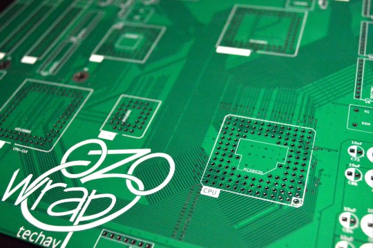
This is the largest, most complex PCB I have ever designed — a 9.6x9.6 inch (244x244mm) square, 4-layer, complete motherboard for my MC68030 homebrew computer project.
It is designed to support the Motorola MC68030 CPU, MC68882 FPU, two 72-pin SIMM sockets, 512kB ROM, two serial ports, one parallel port, PS/2 keyboard, 4-bpp VGA video, IDE hard drive, and three ISA expansion slots. A complete system all in a microATX form factor.
This builds on my previous work with the 68030, based heavily on my wire-wrap project and the boards that followed. It's a project over four years in the making. I have made a few improvements on the old design, like 16550-compatible serial ports and an updated memory map to support much more RAM in a contiguous space.
Keeping with my existing system designs, I've combined most of the logic into a set of CPLDs. This makes things like PCB layout and logic debugging so much easier. Most of the remaining discrete logic on the board is 74'245 bus transceivers for driving memory and the ISA slots.
I've kept the name "wrap030" in honor of the project's origin as a wire-wrapped prototype, despite the move to proper PCBs. It's just what I've been calling the project in my own head (and design files) all this time, so at this point no other name would feel right.
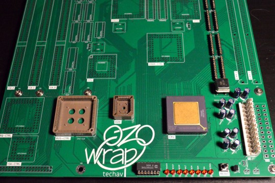
I of course wasted no time starting to assemble one, but I did stop myself from getting too carried away with the soldering iron. I want to be methodical and test each section before moving on to the next.
I have already found one major error in my board layout — the footprint for the VGA connector is backwards. I may need to bodge together some kind of adapter.
So far I've confirmed the minimalist AT power supply section works with no major shorts on power supply rails, and the reset circuit is working as expected. Next step is to try a free run test with the CPU to ensure the system clock and CPU are working. Once that is confirmed working, I can start loading logic for accessing ROM. My goal is to have it at least running BASIC on a serial terminal by VCFSW in June.
I've forked my existing wrap030 repository on GitHub for this new Wrap030-ATX, since it does make some breaking changes that will require updates to logic and programs. New repo is here:
#homebrew computing#mc68030#motorola#motorola 68k#motorola 68030#vintage computing#jlcpcb#vcf southwest#wrap030-atx
32 notes
·
View notes
Text
Top 10 Best vertical jamma board [2022]
Top 10 Best vertical jamma board [2022]
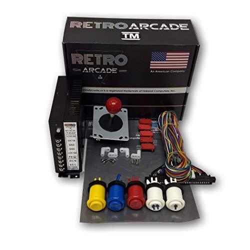
1. Jamma 60-in-1, Mame, Retro PI Classic Arcade Multigame-Multicade Arcade Game Control kit Buy On Amazon Upright arcade 60-in-1 control kit Includes RetroArcade.us Jamma wiring harness with US label Includes RetroArcade.us 16 amp RetroArcade.us power supply Game boards sold separately! 2. TAPDRA Arcade Classics Vertical Jamma Board Support CGA/VGA CRT/LCD PCB 60 in 1 Arcade Machine DIY Board…
View On WordPress
0 notes
Text
KOMPONEN-KOMPONEN KOMPUTER
Komponen – Komponen Komputer
Oleh karena itu, dalam artikel kali ini akan dibahas dan dijelaskan mengenai 20 jenis komponen yang terdapat dalam komputer beserta dengan kegunaannya masing-masing. Untuk mengetahuinya, simak pembahasannya dibawah ini.
1. Motherboard

Secara sederhana, motherboard atau biasa disebut dengan Mainboard, Baseboard adalah Papan Sirkuit Cetak (Printed Circuit Board – PCB). Papan ini menjadi salah satu komponen terpenting dalam sebuah komputer. Sebab, dengan adanya motherboard setiap komponen utama dalam komputer dapat berhubungan dengan komponen lainnya. Motherboard inilah yang menampung seluruh komponen yang memiliki peran penting dalam sistem, seperti CPU, slot RAM, VGA Port, USB Port dan lainnya.
Mengenai fungsinya, Motherboard memiliki fungsi untuk menyediakan akses bagi setiap komponen dalam melakukan komunikasi satu dengan yang lain. Selain itu, motherboard juga berfungsi untuk meningkatkan fleksibilitas dari komputer itu sendiri. Anda dapat menghubungkan beberapa perangkat tambahan, seperti joystick dengan bantuan motherboard.
2. Processor (CPU)

CPU (Central Processing Unit) adalah salah satu jenis perangkat keras dari komputer yang digunakan untuk menangani instruksi yang diberikan. CPU sering juga dikatakan sebagai Processor yang merupakan otak dari sebuah komputer. Sebab, CPU yang mengatur segala aktivitas dan jalannya program yang terdapat dalam komputer.
Misalkan saja, ketika Anda menekan Alt+F4 maka otomatis akan menutup program yang sedang Anda buka. Yang mengatur instruksi tersebut adalah CPU. Sebagai komponen utama, CPU memiliki fungsi penting yang harus Anda ketahui, yaitu menerima instruksi yang diberikan, mengolah instruksi, dan kemudian mengeksekusi instruksi tersebut.
Biasanya, ketika membeli komputer hal yang pertama kali Anda lihat adalah spesifikasi komputer itu. Sebagai contoh, Processor 32-bit jelas berbeda dengan processor 64-bit. Maksudnya, komputer yang memiliki processor 64-bit dapat bekerja jauh lebih baik dibandingkan dengan 32-bit. Dengan begitu, Anda harus lebih teliti lagi dalam menentukan spesifikasi CPU agar sesuai dengan kebutuhan Anda.
3. Heatsink

Heatsink atau PC Cooler merupakan salah satu perangkat keras yang memiliki bentuk fisik seperti kipas yang terbuat dari tembaga dan aluminium. Bukan tanpa sebab heatsink didesain pada setiap komputer atau PC. Dimana tujuan utama dari heatsink sama dengan kipas yang Anda kenal, yaitu memberikan suhu dingin pada processor agar kinerja dari processor tetap stabil dan suhu panas yang dimiliki processor dapat dibuang melalui heatsink ini.
Walaupun demikian, kini banyak jenis heatsink yang beredar di pasaran. Setiap pabrik mendesain heatsink dengan bentuk fisik yang berbeda-beda, namun fungsinya tetap sama. Secara umum, heatsink bekerja dengan cara menerima panas yang dihasilkan oleh processor, kemudian panas tersebut menyebar keseluruh bagian heatsink hingga berkumpul ke bagian inti heatsink. Maka fan yang terdapat dalam heatsink itulah yang membuang suhu panas tersebut.
4. RAM
RAM (Random Access Memory) adalah salah satu jenis perangkat keras komputer yang digunakan sebagai media penyimpanan. Namun, berbeda dengan Hard Disk yang juga digunakan sebagai media penyimpanan. Sesuai dengan namanya, Random yang berarti acak. Maksudnya, RAM memang digunakan sebagai media penyimpanan, namun penyimpanan yang sementara dan hanya dapat diakses ketika komputer dinyalakan dan acak.
Ketika terjadi instruksi oleh processor, maka RAM yang berfungsi untuk menyimpan data dari instruksi itu. Jadi, RAM akan berfungsi apabila komputer masih dalam keadaan menyala, jika telah dimatikan maka instruksi tersebut akan hilang dari RAM.
Bentuk umum RAM yang terdapat dalam sebuah komputer adalah chip. Chip tersebut dapat Anda tambahkan jika terdapat slot RAM dalam motherboard tersebut. Semakin besar spesifikasi RAM yang terdapat dalam komputer Anda, maka semakin cepat juga kinerja dari komputer itu. Sebab, untuk mengambil data yang tersimpan, dengan RAM yang tinggi maka akan mempercepat proses loading data dan program yang akan diakses. Kini, spesifikasi RAM yang umum digunakan adalah RAM DDR 3. Walaupun sebenarnya telah ada RAM DDR4, namun masih jarang ditemukan.
5. Hard Disk

Seperti yang telah disinggung sebelumnya bahwa Hard Disk (HDD) merupakan salah satu perangkat keras komputer yang juga digunakan sebagai media penyimpanan. Umumnya, di dalam Hard Disk terdapat piringan, dimana piringan itulah yang memiliki peran untuk menyimpan data secara permanen. Ketika Anda mematikan komputer, data yang telah Anda simpan sebelumnya akan dapat diakses ketika Anda telah menyalakan komputer. Kecuali, jika Anda menghapus data tersebut secara manual atau terkena virus.
Jauh berbeda dengan RAM yang hanya dapat menyimpan data atau instruksi selama komputer masih menyala, dengan Hard Disk maka Anda dapat menyimpan data, seperti program, dokumen, gambar, audio atau video secara permanen dalam komputer Anda. Dengan RAM, Anda tidak perlu takut kehilangan data, karena Hard Disk memiliki kemampuan untuk dilakukan backup, yaitu mengembalikan data yang hilang.
Jika Anda pernah mendengar istilah partisi, maka Hard Disk yang dapat dipartisi. Pengertian partisi disini adalah Anda dapat membagi penyimpanan yang dimiliki Hard Disk kedalam beberapa bagian yang dikehendaki. Biasanya, Hard Disk dipartisi menjadi 2 bagian, yaitu sebagai penyimpanan data-data pribadi dan penyimpanan data operating system.
6. VGA Card (GPU)

VGA Card (Virtual Graphic Array) merupakan suatu perangkat keras komputer yang digunakan untuk mengolah dan menerjemah output ke dalam monitor. VGA Card sering juga dikatakan sebagai Video Graphic Adapter. Kehadiran VGA Card dalam sebuah komputer tidaklah memberikan pengaruh yang besar seperti komponen vital komputer lainnya. Penggunaan VGA lebih mengarah kepada hal yang berhubungan dengan grafis, seperti desain 3D ataupun gaming.
Fungsi utama dari VGA Card adalah mengubah sinyal digital yang dihasilkan oleh komputer menjadi tampilan grafik melalui monitor. Dengan begitu, komputer yang tidak memiliki VGA, biasanya tampilan layar menjadi kurang bagus dan tidak menarik. Kini, telah banyak perusahaan yang menghasilkan VGA Card, diantaranya NVidia, 3DFX, S3, ATi Matrox, SiS, Cirrus Logic, Tseng, Trident dan sebagainya.
7. Flashdisk

Flashdisk atau sering juga disebut USB Drive adalah suatu media penyimpanan dalam komputer. Penyimpanan data tersebut bersifat non-volatile, yaitu data tidak akan hilang walaupun tidak terdapat aliran listrik di dalamnya. Selama data tersebut tidak dihapus, maka data tersebut akan tetap ada tanpa aliran listrik. Flashdisk dapat terhubung ke komputer melalui port USB yang terletak dalam motherboard.
Mengenai bentuknya, flashdisk memiliki komponen lebih sederhana dibandingkan dengan media penyimpanan seperti Hard Disk. Flashdisk menjadi alternatif sebagai pengganti hardisk untuk menyimpan data pribadi dan mudah untuk dibawa kemana-mana karena ukurannya yang kecil.
Awalnya, flashdisk memiliki ukuran kapasitas sebesar 512 MB. Namun seiring berkembangnya teknologi, kapasitas flashdisk terus dikembangkan, mulai dari 1 GB, 2 GB, 3 GB, 4 GB, 8 GB, 16 GB, 32 GB dan seterusnya. Selain itu, kini flashdisk banyak digunakan orang karena harganya yang terjangkau dibandingkan dengan membeli hard disk.
8. Monitor

Monitor merupakan jenis perangkat keras (hardware) yang berperan sebagai komponen keluaran (output). Monitor sering juga disebut dengan layar komputer. Layar itu digunakan untuk menampilkan hasil pengolahan data kedalam bentuk grafis. Perangkat ini memiliki peranan yang sangat penting. Sebab, tanpa adanya monitor maka perangkat komputer lainnya tidak dapat diamati secara langsung, kecuali dengan menggunakan perangkat output lainnya, seperti projector.
Beberapa jenis monitor yang terdapat selama perkembangannya, yaitu CRT (Cathode Ray Tube), LCD (Liquid Crystal Display), LED (Light Emitting Diode), dan monitor Plasma. Untuk jenis monitor yang umum digunakan saat ini adalah LCD dan CRT.
Jenis resolusi monitor dapat diketahui dari ukuran LCD dalam ukuran inchi. Misalnya, ukuran layar monitor 17-inchi dapat memiliki resolusi 1024 x 768. Selain jenis monitor dan resolusi layar, ada beberapa faktor yang mempengaruhi kualitas dari monitor, yaitu sebagai berikut :
Dot Pit, menyatakan jarak antara dua pixel. Makin kecil jaraknya, maka kualitas keluaran yang ditampilkan akan semakin bagus dan warnanya yang tajam.
Refresh Rate, menyatakan seberapa banyak monitor di-refresh dalam satuan detik. Makin cepat nilai refresh rate maka gambar yang ditampilkan akan semakin bagus.
Convergence, menyatakan tingkat kejernihan dan ketajaman pixel.
9. Keyboard

Keyboard adalah suatu perangkat keras pada komputer yang berperan sebagai komponen input, yaitu perangkat yang berfungsi sebagai alat untuk menginputkan data yang berupa huruf, angka atau simbol dan menyampaikannya ke CPU (Central Processing Unit) untuk diubah menjadi sinyal-sinyal digital yang dipahami oleh Processor.
Seiring berkembangnya teknologi komputer juga mempengaruhi perkembangan keyboard. Saat ini, keyboard sudah menggunakan format standar QWERTY, yang sudah diakui sebagai standar Internasional. Secara fisiknya, keyboard terdiri dari papan ketik yang memiliki berbagai macam tombol, dimana tombol tersebut dilengkapi dengan fungsinya masing-masing sehingga dapat mengolah proses yang dibutuhkan pengguna.
Secara umum, keyboard QWERTY mempunyai tombol atau papan ketik sebanyak 101 buah dengan susunan sebagai berikut :
Alphanumeric Key : Tombol ketik yang berisi huruf, angka dan tanda baca, dimana susunan yang digunakan saat ini adalah standar QWERTY.
Numeric Keypad : Merupakan bagian khusus pada keyboard yang berisi angka yang digunakan untuk melakukan operasi perhitungan.
Function Key : Tombol ketik ini digunakan untuk menjalankan perintah khusus yang berhubungan dengan sistem operasi maupun program dalam komputer.
Control Key : Tombol yang menyediakan kontrol terhadap kursor dan layar, seperti Home, End, Delete, Insert, Page up dan lainnya.
10. Mouse

Mouse adalah perangkat keras yang berfungsi sebagai komponen inputan, yaitu menerima inputan yang diberikan oleh pengguna. Dinamakan mouse, dikarenakan bentuk fisiknya menyerupai seekor tikus, dengan kabel yang dapat dihubungkan dengan komputer yang menyediakan port didalamnya.
Jika diperhatikan, mouse dilengkapi dengan berbagai tombol datar, seperti klik kanan yang berfungsi untuk membuat menu Options, klik kiri yang berfungsi untuk memilih menu; apabila diklik dua kali dapat berfungsi untuk membuka aplikasi atau program dalam komputer, tombol scroll yang dilengkapi dengan sensor untuk menaikkan atau menurunkan kursor.
Terdapat beberapa jenis mouse yang beredar dipasaran berdasarkan pendeteksiannya, yaitu : mechanical mouse, optomechanical mouse dan optical mouse. Dibalik keberhasilan mouse saat ini, ada tokoh yang berhasil menemukannya yaitu Douglas Engelbart.
11. Optical Drive

Apakah Anda mengenal CD atau DVD ? Kedua alat tersebut merupakan jenis media penyimpanan yang termasuk kedalam perangkat keras jenis Optical Drive. Dengan begitu, optical drive adalah perangkat keras yang memiliki fungsi yang sama dengan hard disk atau flashdisk, yaitu sebagai media penyimpanan. Terdapat beberapa jenis optical drive, yaitu :
CD-ROM (Compact Disk – Read Only Memory) : merupakan suatu alat dapat digunakan sebatas membaca CD
CD-RW (Compact Disk – Rewritable) : merupakan alat yang dapat melakukan dua fungsi, yaitu membaca CD dan menulis CD
DVD ROM (Digital Video Disk – Read Only Memory) : merupakan alat yang dapat membaca CD dan DVD
DVD Combo : merupakan alat yang selain dapat membaca CD dan DVD juga dapat menulis CD, namun tidak dapat menulis DVD
DVD RW : merupakan alat yang memiliki fungsi komplit, yaitu selain dapat membaca keping CD dan DVD juga mampu untuk menyimpan atau menulis keping CD dan DVD.
12. SSD

SSD merupakan singkatan dari Solid State Drive atau Solid State Disk, yaitu perangkat untuk menyimpan data dengan menggunakan serangkaian IC (Integrated Circuit) yang berperan sebagai memori untuk menyimpan data secara persisten.
Pada umumnya, SSD memiliki fungsi yang sama dengan Hard disk. Namun, SSD merupakan sebuah inovasi dalam penyimpanan data. Dengan SSD, data disimpan pada chip-chip memory flash berbasis NAND yang terhubung satu sama lain. Chip tersebut memiliki kecepatan yang lebih tinggi dibandingkan flash disk.
Kalau dahulu Anda mengenal floppy disk, kini posisinya telah tergeser dengan adanya hard disk. Begitu juga dengan hard disk yang harus tergeser dengan adanya SSD. Walaupun begitu, SSD belum banyak diketahui oleh pengguna komputer. Sebab, harganya yang begitu tinggi dan cukup fantastis.
13. Power Supply

Pernahkah Anda memperhatikan ketika sumber listrik padam, namun komputer masih tetap menyala ? Itu karena adanya perangkat yang disebut dengan power supply. Power supply merupakan suatu perangkat keras yang memiliki fungsi untuk mensuplai daya/tegangan ke dalam komponen komputer. Daya tersebut disuplai menuju motherboard, harddisk, heatsink dan lainnya.
Mengenai fungsinya, power supply bertujuan untuk mengubah tegangan arus AC menjadi DC. Saat ini, ada beberapa jenis power supply, yaitu :
Power supply AT Power supply jenis ini memiliki bentuk dimana kabel power yang akan dihubungkan ke motherboard terpisah menjadi dua konektor, yaitu konektor P8 dan konektor P9. Dengan demikian, pada saat pemasangan diperlukan ketelitian agar tidak terjadi kesalahan dalam pemasangannya.
Power Supply ATX Jenis power supply ini memiliki kabel dengan jumlah 20 pin yang telah disusun menjadi satu kesatuan untuk dihubungkan ke motherboard. Sangat jarang terjadi kesalahan dalam pemasangan jenis power supply ini.
14. LAN Card

LAN Card sering disebut dengan NIC (Network Interface Card), Ethernet Card atau kartu jaringan. Perangkat ini digunakan untuk menghubungkan beberapa komputer dengan jaringan, terutama dalam area LAN. Misalnya, jaringan komputer pada suatu gedung, satu rumah , satu kantor dan lainnya. Biasanya, LAN Card dipasang pada slot PCI yang terdapat di motherboard.
Pada umumnya, terdapat dua jenis NIC, yaitu NIC yang bersifat fisik dan logis. Contoh NIC yang bersifat fisik adalah Token Ring, NIC Ethernet dan sebagainya. Sedangkan contoh NIC yang bersifat logis adalah Loopback Adapter dan Dial-up Adapter.
Pada setiap NIC telah diberikan nomor alamat yang dikenal dengan sebutan MAC Address yang bersifat statis. Maksudnya dapat diubah oleh penggunanya. Saat ini, seiring dengan berkembangnya teknologi LAN card memiliki dua jenis utama, yaitu LAN Card Kabel dan LAN Card Wireless.
15. WLAN Card

WLAN Card atau Wireless LAN Card atau biasa juga disebut WiFi Adapter merupakan perangkat komputer yang berhubungan dengan jaringan. Fungsinya sama seperti LAN Card, yaitu menghubungkan komputer dengan akses jaringan. Akan tetapi, dengan adanya WLAN lebih memudahkan Anda dalam melakukan koneksi jaringan tanpa harus membawa kabel kemana-mana hanya untuk menghubungkan dengan jaringan.
Wireless Card memungkinkan komputer terhubung ke jaringan tanpa menggunakan kabel. Cara kerja dari Wireless Card ini adalah wireless akan menerima sinyal yang berasal dari perangkat jaringan, seperti Access Point. Pada umumnya, komponen-komponen dalam WLAN adalah :
Mobile atau Desktop PC, dimana untuk mobile PC dapat terpasang pada port PCMCIA, sedangkan untuk desktop PC melalui PCI Card atau USB.
Access Point, perangkat yang dapat mengkonversi sinyal frekuensi radio (RF) menjadi sinyal digital melalui media kabel.
WLAN Interface, peralatan yang dipasang di Mobile atau desktop PC dalam bentuk PCMCIA (Personal Computer Memory Card International Association), PCI Card maupun melalui port USB
Antena, digunakan untuk memperkuat daya pancar.
16. Sound Card

Sesuai dengan namanya¸Sound Card berkaitan dengan kebutuhan audio dan suara dalam suatu komputer. Misalkan saja, ketika Anda mendengarkan suara yang berasal dari komputer menggunakan headset atau speaker, maka suara yang Anda dengar itu diolah Sound Card. Beberapa jenis sound card berdasarkan cara pemasangannya dalam komputer atau laptop, yaitu :
Sound Card Onboard Pada umumnya, sound card ini terpasang langsung (menempel) pada motherboard komputer. Sound card jenis ini berupa chipset yang terpasang langsung dengan motherboard sehingga kinerjanya dipengaruhi oleh processor.
Sound Card Offboard Sound Card offboard ini dipasang ke slot ISA atau PCI. Keunggulan dari sound card jenis ini adalah kualitas suara yang dihasilkan menjadi lebih bagus dibandingkan sound card onboard.
Sound Card External Umumnya, sound card external ini dipasang ke komputer menggunakan port USB. Sound card jenis ini cocok digunakan untuk melakukan perekaman suara.
17. Printer

Printer termasuk kedalam perangkat keras (hardware) yang berperan sebagai komponen output. Perangkat ini berfungsi untuk menampilkan data dalam bentuk cetakan, baik itu kertas, gambar ataupun grafik.
Selain berfungsi untuk menampilkan cetakan dokumen, kini printer juga memiliki fungsi lain, seperti menggandakan dokumen, memindai dokumen serta berfungsi untuk mengirim data (fax). Dimana pada awalnya, printer hanya digunakan untuk mencetak dokumen yang menampilkan data yang berupa teks, gambar ataupun grafik dalam lembaran kertas.
Dengan kehadiran printer, maka dapat memudahkan orang yang memiliki keperluan untuk mencetak dokumen. Jenis-jenis printer yang banyak beredar di pasaran adalah printer dot matrix, printer ink jet dan printer laser jet.
18. Scanner

Scanner merupakan komponen inputan, yaitu alat yang digunakan sebagai pemindai atau menduplikat dokumen atau objek secara digital dan disimpan kedalam komputer. Scanner itu sendiri memiliki banyak jenis dan bentuk. Berikut mengenai beberapa bentuk scanner yang beredar di pasaran :
Scanner Drum Sesuai dengan namanya, scanner drum ini berbentuk seperti drum atau tabung. Jenis scanner ini merupakan jenis scanner yang luar biasa. Sebab, resolusi gambar yang dihasilkan cukup tinggi, dimana resolusi mencapai 24000 ppi (pixel per inch). Terdapat beberapa keunggulan yang diperoleh dari scanner drum, yaitu dapat melakukan proses scan dokumen kuno, jumlah getaran yang dihasilkan sangat minim, dapat melakukan scanning pada dokumen yang berbentuk kertas yang besar
Scanner Flatbed Disebut flatbed karena bentuk fisiknya yang datar, seperti tempat tidur. Inilah jenis scanner yang sering dijumpai di dunia scanning dokumen. Hal itu disebabkan karena ukurannya yang kecil dan kompatibel dengan beberapa ukuran kertas standar, seperti legal, letter hingga A3. Untuk melakukan pemindaian terhadap dokumen dengan menggunakan teknologi CCD (Charge Coupled Double).
Film Scanner Jenis scanner ini digunakan untuk menyimpan foto dan video menggunakan teknologi negative. Namun sayangnya, jenis scanner ini sudah jarang digunakan. Dengan menggunakan film scanner dapat melakukan konversi dan mengubah objek yang disimpan dalam film negative menjadi bentuk digital.
Roller Scanner Roller scanner merupakan jenis scanner yang memiliki fungsi yang sama dengan flatbed scanner, yaitu melakukan pemindaian pada sebuah dokumen atau gambar secara fisik berbentuk lembaran. Yang membedakannya dengan flatbed adalah metode yang digunakan. Jika flatbed menggunakan teknologi CCD dengan menjadi mata yang digerakkan untuk memindai dokumen, sedangkan roller menggunakan dokumen yang digerakkan.
19. Speaker

Speaker adalah suatu perangkat keras yang berperan sebagai komponen keluaran, dimana speaker dapat mengeluarkan output dari CPU yang berupa suara atau audio. Speaker dalam komputer terdiri dari bagian yang saling berhubungan satu dengan yang lainnya. Berikut ini adalah bagian-bagian yang terdapat dalam speaker :
Sekat rongga (conus) Komponen ini berfungsi untuk menghasilkan gelombang tekanan yang disebabkan oleh gerakan udara yang dapat menghasilkan suara.
Membran Komponen ini berfungsi untuk menerima proses induksi yang berasal dari magnet, dimana proses tersebut menghasilkan bunyi yang berasal dari getaran yang dihasilkan.
Magnet Komponen yang berfungsi sebagaimana magnet pada umumnya, yaitu menghasilkan medan magnet untuk melakukan proses induksi yang berasal dari membran tersebut
Kumparan Komponen ini berfungsi untuk menyalurkan energi gerak menuju conus. Kumparan tersebut dapat bergerak disebabkan oleh perubahan yang terjadi pada medan magnet.
Casing Bagian ini digunakan untuk melindungi seluruh komponen vital yang terdapat dalam speaker. Sudah begitu banyak model casing yang beredar dipasaran, misalnya berbahan kertas, plastik, logam atau bahan lainnya.
20. Webcam

Webcam atau disebut dengan Camera Web adalah istilah kamera yang dapat dihubungkan dengan komputer. Pada umumnya, fungsi webcam hampir sama dengan fungsi kamera pada umumnya, yaitu memudahkan Anda dalam mengolah pesan seperti chat melalui video secara real-time.
Webcam biasanya terdiri dari sebuah lensa yang dipasang dalam papan sirkuit yang dapat digunakan untuk menangkap sinyal gambar, casing (cover) dan kabel support. Sebuah webcam dilengkapi dengan software, dimana software ini berfungsi untuk mengambil gambar-gambar yang berasal dari kamera digital dalam interval waktu tertentu untuk dihubungkan melalui koneksi internet.
Sebuah webcam dirancang bukan untuk menyimpan gambar. Sebab, fungsi utama webcam disini hanyalah untuk merekam dan mengirimkan gambar yang ditangkap langsung oleh komponennya. Hingga kini, webcam masih dapat dijumpai di pasaran dengan harga yang bermacam-macam tergantung dengan fitur dan kemampuan dalam menangkap gambar.
Itulah beberapa jenis komponen komputer beserta fungsinya lengkap dengan gambarnya. Dengan demikian, Anda dapat mengetahui setiap komponen yang terdapat dalam komputer Anda dan dapat memahami fungsinya dengan baik dan benar.
1 note
·
View note
Text
How To Open Pcb File On Phone

Up to now, smart phones have become such a must-have electronic product that more than one third of daily communications and activities are completed through smart phones with their value rapidly rising every year. It's estimated that mobile phones featuring language will be decreased as a rate of 23.5% by 2020. Best docker bittorrent client. Contrarily, smart phones at all levels will maintain a growth trend of 8.0% by 2020, including low-cost and low-functioning smart phones, medium smart phones and high-end smart phones.
Pcb Open For Business
After that, please open the.drl file pertaining to the drilling plane of the PCB being processed (in this example, that’s P1263 – Drill Data.drl), by clicking on File / Open Excellon. In the box on the right of the related dialog box, the holes of the PCB’s pads will appear; please click on Tool / Double-Side PCB Tool. This page explains how you can easily convert a.pcb file to a PDF using free and easy to use tools from PDF24. The methods to create PDF files explained here are free and easy to use. A PDF creator and a PDF converter makes the conversion possible. The PDF24 Creator installs for you a virtual PDF printer so that you can print your.pcb file on that printer in order to convert your file to PDF. Is an excellent pcb layout design software tool to create professional printed circuit board ( PCB ). It is a flexible easy to use CAD program, which allow you to realize your projects in a short time. With ZenitPCB Layout is possible to create the project starting both from the schematic capture or by the layout itself. .PCB file is associated with Printed Circuit Board Design File developed by N/A, has a N/A Format and belongs to Data Files category. How to open a.PCB file? Execute.PCB file by double-clicking on it. If you have already installed the software to open it and the files associations are set up correctly,.PCB file will be opened. The manufacture of your board depends upon you supplying complete and accurate information in your PCB design file. Learn about the essentials for PCB design files. Although, being challenged as the Printed Circuit Board file standard Gerber files are still the most used format. Learn about the advantages and disadvantages of Gerber files.
Apart from ordinary functions like voice communication and emailing, smart phones today should conform to functions that are equivalent to PCs' including webpage browsing, online communication and service and social media etc. Furthermore, the latest operation system allows smart phone users to easily download windows with particular functions and multi-media self-customized software and smart phones today are even capable of connecting with smart watches, PCs, home appliances and on-board equipment to meet more demands of people. When it comes to appearance and dimensions, smart phones will develop towards large scale but thinness. In the future, smart phones with thickness less than 8mm will become a main stream. Monitors move to high definition (HD) and large screen. The equipped camera will be upgraded from 16-million pixels to 20-million pixels. Besides the expected modifications introduced above, other specification modifications of smart phones are summarized into table below.
Item201420182024Average external dimensions(W×L×H/mm)77.5*152.8*8.575*150*8.070*145*7.0Average volume (cm3)/weight(g)100/17190/16071/150Power consumption in calling(W)0.6-1.20.5-0.90.4-0.6MonitorDisplay deviceLCD, OLEDLCD, OLED, Flex LCD, Color electronic paperLCD, OLED, flex LCD, Color electronic paper, Spontaneous emission componentsDimensions (in)4.95-6.05.7-7.05.0-7.5DefinitionWide-VGA-Wide-XGA High-Definition TV(1080P)Wide-VGA-Wide-XGA+ Full High-Definition TV(4K)Wide-SVGA-Wide-SXGA Full High-Definition TV(8K)CameraModeCMOSResolution (million)8-208-248-40Near Field CommunicationInfrared communication, Bluetooth, NFC, wireless LAN, WiMAXBluetooth, NFC, Wireless LAN, WiMAX, millimeter waveMaster Record DeviceInternal storage, Memory card web serverInternal storage, Memory card cloud serverBatteryLithium-ion battery, Li-polymer batteryLithium-ion battery, Li-polymer battery, Solar cell, Fuel cell
Based on functions and development trend of future smart phones, highly multi-layer printed circuit boards should be applied as mother board and low multi-layer PCBs as complementary daughter board. When it comes to the fabrication of mother boards, 10-layer build-up multilayer (BUM) PCBs are usually selected. Owing to function integration led by semiconductor packaging (SiP), it's extremely likely that layer count will maintain unchanged or even reduced. Since the year of 2015 witnessed the application of 64-bit processor and IC pin spacing has been shrinked from 0.4mm to 0.35mm, layer count of mother board will possibly increase to 12 layers or more for the time being. The development trend of board structure and distribution in smart phones are summarized in the following table.
Item201420182024PCB Count1-30-3Motherboard TypeBUM PCBBUM PCB, Glass PCBMotherboard Dimensions (mm)50*50-55*120Layer Count of Smartphone MotherboardPCB8-128-106-10Sum of Components on Smartphone Motherboard PCB500-1300500-1000Min Dimension of Components (mm)0.4*0.2Sum of LSI16-2814-2510-20FPGASum7-146-135-12Min Spacing (mm)0.40.350.25Max Terminals10441200Sum of Function Modules5-154-123-10Sum of Connectors5-204-153-10
Technological design of PCB is so important that it plays a key role in manufacturing PCBs effectively with low cost. A new generation of surface mount technology (SMT) requires that designers have to take manufacturing issues into consideration from the beginning due to its complexity since a little modification of design files will definitely lead to delayed production time and increased development cost. Even a change of a pad position requires rerouting and solder paste stencil remanufacturing. The situation becomes tougher for analog circuits that strive for both redesigning and retesting. Nevertheless, if issues maintain unsolved, more loss will be caused in volume production in the end. Therefore, designers must pay full attention to technological issues from the beginning. One simple rule: the earlier technological issues are solved, the more beneficial it'll be for manufacturers.
Elements that should be taken into account in terms of technological design of smart phone circuit boards include: • Transmission line, positioning hole and fiducial marks compatible with automatic manufacturing and assembly; • Panels associated with manufacturing efficiency; • PCB material, PCBA method, component distribution & packaging type, pad design and soldermask design related to soldering percent of pass; • Component spacing and test pad design connected with inspection, rework and testing; • Silkscreen or corrosion characters associated with assembly, debugging and wiring.
a. Laminate multilayer PCB
Laminate multilayer PCB fabrication technology is a type of multilayer PCB fabrication technology that is currently being widely applied. During the application of laminate multilayer PCB fabrication technology, substractive process is applied to manufacture circuit layer. Interconnection between layers is achieved through stages of lamination, mechanical drilling, electroless copper and copper plating. Finally come solder mask, solder coating and silkscreen to complete a piece of circuit board.
b. BUM technology
On insulating substrate board or traditional double-sided or multi-layer board, coated insulating dielectric is applied to form leads and through holes through chemical copper plating and electrical copper plating. The process continues over and over again until multilayer PCB with demanded layer count is finally manufactured. The optimal feature of BUM PCB is that substrate layer is so thin, trace width and spacing so low and via diameter so small that it features so high density. Thus, it can be applied in IC-grade high-density packaging.
c. Fiducial marks
As a generally-accepted rule, each side of daughter board in smart phones should have at least 2 fiducial marks. When space is actually so limited, they can be flexibly arranged. They should be designed to be a circular graphic whose diameter is 1mm (40mil). With contrast between material color and environment, solder mask area should be left 1mm (40mil) larger than fiducial marks and no character is allowed. When real estate is so limited, size of solder mask area can be arranged to be 0.5mm wider but solder pads with the same color shouldn't be designed within a range of 3mm.
Additionally, fiducial marks on the same board should feature the same internal background, that is, they should keep compatible in copper coating. A lonely fiducial mark with no routing around should be designed to be a protective circle with an internal diameter of 3mm and circular width 1mm. Moreover, coordinate figures must be featured by fiducial marks that shouldn't be regarded as a sign after PCB design.
Best torrent client with search engine 6.4. d. Panel Design
• Double-side v-groove panel method works well for square PCBs with attributes of neat margins after breaking up and low manufacturing cost. Thus, it is firstly suggested. Generally, an angle of 30 degrees is applied with its thickness to be one fourth or third of board thickness. However, this method doesn't fit for printed circuit boards with ICs with BGA or QFN packages.
• Long-slot hole plus circular hole must be applied in mother boards with more than 4 layers while other daughter boards such as button board, LCD board, SIM card board and TF card board should select panel method based on the figure and shape of printed circuit boards. It's suggested that long-slot hole plus circular hole should be applied to arc or irregular shapes. Our article of The Surprising Secret to Designing Combination Method of PCB Panels will tell you more combination methods in terms of panel design.
As people's must-have devices, smartphones are developing towards intelligentization, miniaturization and multi-functions, thereafter requiring higher demands for PCBs that conform to all the functions of electronic devices. If you need a reliable PCB production partner to manufacture your smartphone PCBs, PCBCart can help. We have been providing quality guarantee full PCB production services for companies from telecommunications fields for 10 years. Minitool partition wizard alternative. Our experience and experts allow you to get the best ever circuit boards at cost effective price.
Require bare board PCB fabrication and assembly service for telecommunication devices? Get your PCB price using our PCB quote system, it is super easy and totally FREE! Shall you have any questions on how PCBCart manufacture smartphone PCBs or electronic boards for other telecommunication applications? Contact our experts at anytime!
Helpful Resources: • How to Design High-Quality PCBs • The Key PCB Design Rules You Have to Know • Commonly Seen PCB Design Issues • Possible Problems and Solutions in the Process of PCB Design • Full Feature PCB Manufacturing Service from PCBCart - Multiple Value-added options • Advanced PCB Assembly Service from PCBCart - Start from 1 piece
Previous articleMethods Contributing to Optimization of LED PCB Design and Quality Control
Pcb Open For Business
Next articleHow to Defeat Control Power Supply Grounding Defects Based on Insulation Reduction in PCB Design
0 notes
Photo
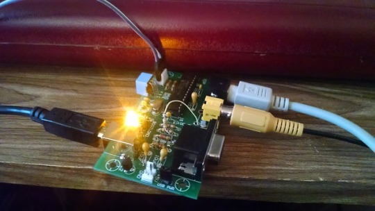
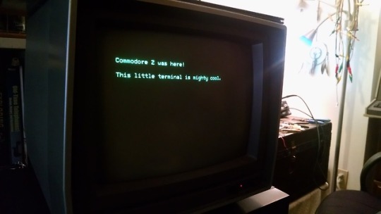
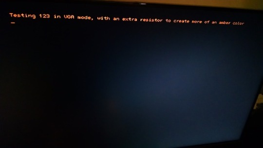
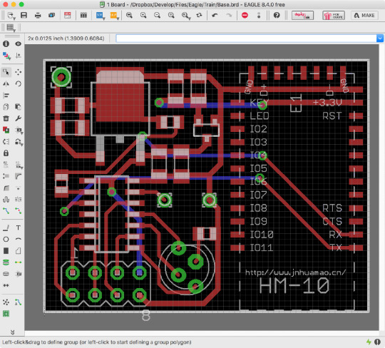
@tumblokami ordered up some PCBs and gathered the parts to make a few of Geoff Graham’s ASCII Video Terminal board kits.
I enjoy small projects like this that serve a unique compact function, and I certainly can find a use for another serial terminal. It provides VGA or composite video output, PS/2 input, and TTL serial output (which I adapted to RS232 voltage levels).
34 notes
·
View notes
Text
Computer Fundamentals - 2073

Example of a laptop computer Attempt (Any Ten) questions: - What is computer? Write down the features of 4th generation computer. Computer is an electronic machine which accepts data and instructions given by the user (input), processes them according to the given instructions (processing) and produces 100% accurate result(output) which can be further stored for current as well as future uses(storage). Various features of 4th generation computer are as listed below: - Its speed of processing is very high. - It consumes extremely low amount of electricity in comparison of its predecessor generations. - The main component used for processing in this computer is microprocessor. - It is very smaller in size. - The latest computers of this generation are so much small that they can be either easily transported from one place to another or even worn on hands. - It has very large storage capacity. - Write down the characteristics of computer. The characteristics of computer are as listed below: - It should be faster in processing speed. - It should be able to handle a large amount of data. - The output produced by a computer should be 100% accurate and reliable. - A computer be versatile i.e. it should be applicable in various fields. - A computer should be diligent i.e. it should get bored or tired of doing works. - A computer should not have any feelings. - It should operate on electricity. - It should be programmable i.e. it can be used to achieve any goal with respect to its programmability. - Differentiate between RAM and ROM. RAM and ROM are as differentiated below: RAM ROM It is a temporary memory. It is a permanent memory. It is volatile memory i.e. its content gets deleted once the electricity cuts off. It is non-volatile memory i.e. its contents remain unchanged even if the electricity cuts off. It is generally used for loading system files and temporary application files. It is generally used to store the vendor's information and contact details as well. It can easily be upgraded with respect to the demand of user. It remains inbuilt into the motherboard hence can't be further upgraded easily. - Explain the term BIOS. BIOS is an abbreviation for Basic Input Output System. This system mainly deals with the checking of various input and output peripherals at the time of system booting. It also notifies in case any important peripheral is missing or damaged. This is the topmost instruction being carried out once the power button of a computer is pressed. It also tells the computer about the addresses from where the devices or system logs can be accessed for further processing. Loading device driver into computer's memory is also a step being defined in BIOS. - What is hardware? Write about CPU and motherboard. The physical components of computer that can be touched or felt is known as hardware. As the name suggests, hardware can be physically touched or stored in a physical location. Various examples of computer hardware are: keyboard, mouse, monitor, CPU, Hard Disk, etc. - CPU:- CPU is an abbreviation for Central Processing Unit. It is the main component of processing in fourth generation computer. The major task of CPU is to perform the instructions being fed into the computer system. It is the only place that carries out processing action of the instructions. Hence it is also called as "the brain" of a computer system. A CPU can be further divided into three parts. They are: - ALU(Arithmetic & Logic Unit):- This part of CPU is responsible for carrying out various arithmetical operations such as addition, subtraction, multiplication, division, etc. as well also the logical operations such as Logical AND, OR, NOT, etc. Any number system is converted into binary number system and then performed operation. Then once again, the result is converted into original number system for easy understanding of the user. - CU (Control Unit):- This part of CPU is responsible for controlling the various the instructions to be processed by a CPU. This unit also defines the priority for any task and then arranges the instructions sequentially to perform any task. This unit is also responsible to take decision for the devices where the data or information should reach. For e.g.: displaying operation is sent to VGA, playing sound is sent to speaker, printing documents is sent to printer, etc. - MU (Memory Unit):- This part of CPU is responsible for storing the data and instructions that is related to CPU. Various data and instructions prior to processing or even after processing are stored into this unit for further transmission. Memory Unit can be further divided into two categories: Primary Memory and Secondary Memory where the data to be processed or operated by CPU are stored in Primary Memory whereas the result produced after processing by CPU is stored in Secondary Memory. - Motherboard:- As the name implies, motherboard can be termed as "mother" of all the boards i.e. it connects every devices together for further communication. Since individual connection of every devices to remaining devices would form a meshy structure, hence motherboard is used to attach or connect every devices together. Almost all the devices are directly connected to motherboard either for power supply or for data transmission. The circuit is not possible by using individual wires for every connection, hence the circuit is being printed on a plastic body with metallic material that results the conduction or passing of electricity to every electronic devices. Hence motherboard is also known as PCB (Printed Circuit Board). - Explain the types of storage devices. The various types of storage devices are as explained below: - Magnetic tapes: The storage devices in which magnetic tapes are used to store data are known as magnetic tapes. Data and information are written or read in sequential mode i.e. the part of the tape under the read/write head is only accessed at a time. So collecting data from this type of devices is time consuming and slower in comparison to other storage devices. They are also known as primitive types of storage devices which are out of use at present. Any physical touch to the magnetic tapes of the devices may corrupt the data and result in corruption of data. The chances of spreading viruses is also very high as a single touch may result corruption of data. Example: VCR, audio cassettes, etc. - Magnetic disks: The storage devices in which magnetic disks are used and are divided into the form of tracks and sectors are known as magnetic disks. Since the data are not accessed sequentially, these types of storage devices are also known as Random Storage Devices. But storage or accessing process require the physical movement of disks inside the device, so it may be prone to get damaged soon. In comparison to magnetic tapes, magnetic disks are more reliable and faster for data communication as it supports Random Access of data. Example: Hard Disk, Floppy Disk, etc. - Flash memory: The storage device that uses semiconductor chips for storage of data is known as flash memory. Semiconductor memories are generally smaller and portable in size. So they are also called removable disks. They have no any physical movement related parts for read/write process. Hence they are also long time durable in case of proper uses. Example: pen drive, memory cards, etc. - Optical Storage Devices: The devices in which data or instructions are stored optical form and require laser reader to access the stored data. They are generally write once type of storage devices i.e. the data once written can neither be edited nor any new data can be added. But also RW (Re-Writable) optical storage devices are available in which data can be written as many times as required. But the problem is that, adding any newer data needs to delete all the older data. Generally write once type of devices are cheap and mostly used in the market which is the root cause of virus transmission. So the newer computer systems have completely eliminated the use of optical storage devices and the current trend of storage is shifting towards external magnetic disks such as external hard disk, pen drives, memory cards, etc. Some of the examples of optical storage devices are Compact Disk (CD), Digital Versatile Disk (DVD), etc. - Solid State Drive (SSD): It is the most trending storage devices till date. It uses various semiconductor memories together being connected using NAND gates. No any magnetic disk is used that results no any physical movement inside the disk while accessing this device. In comparison to other storage devices, it is extremely fast and results a better a computer experience. - Differentiate between serial port and parallel port. Serial Port Parallel Port Data is transmitted serially through this port. Data is transmitted parallel through this port. Data transmission speed is slower than parallel port. Data transmission speed is faster than serial port. It has generally less number of wire connections. It has generally large number of wire connections. It sends data bit by bit streams after sending a bit at a time. It sends multiple bit streams at a time. It generally uses male jacks. It generally uses female jacks. Modems, device controllers, security cameras, etc. use serial port. CD Drivers, printers, hard drives, etc. use parallel port. - What is Operating System? Write down its functions. The system software that manages the overall functions of a computer system and also tells the computer what to do and how to do is known as an operating system. The various functions of Operating System are as follows: - Memory management: It manages the amount of memory required by any application and also frees that memory when the application is closed. - File management: Although the data or information is stored in various storage devices, Operating System defines creates a cluster or a system pattern to store files and directories. - Security management: The administrative rights of a computer are defined by an operating system. Hence it enables to secure the computer system on the basis of various levels of users. - Resource management: It queries the conditions and checks the availability of various resources available to a computer system such as hard disk, printer, etc. - User interface: An operating system provides an interface where a user can interact with computer resources. - Batch execution: An operating system also provides the facilities to perform a same type of task on various data or files which is concluded as batch execution. - Define application program. Explain about device driver and its importance. The program designed to meet the specific goal of user rather than the smooth functioning of computer system is called application program. For example: mspaint is developed for users to draw, microsoft word is developed to type various letters and official documents, etc. The utility software that helps the computer to identify a specific device and also instructs the way how to interact with that device is known as device driver. It mainly introduces the device to computer. In case device driver of a device is not present in computer, that computer cannot work with that device as it can't identify the device. The absence of proper device driver may result in the malfunctioning of computer as well as that device too. Device driver is very much important for a computer. Device driver also preserves the right to identify the administrative rights and decide either to send or receive data to/from that device into computer. Every computer must have device driver of every devices connected to it. Generally most of the devices' device drivers are installed by default but in some cases such as adding new printer, scanner, fax, etc. may require the computer to have its device driver. - What do you mean by browser? Highlight the concept of WWW and FTP. A computer program that helps us to open various websites is simply referred to as browser or web browser. Examples of browser are: opera mini, UC browser, Google Chrome. Browser understands the language of HTML (HyperText MarkUp Language) and converts it into an attractive and responsive page called webpage. WWW:- WWW is an abbreviation for World Wide Web. It is one of the most important services of internet. This features enables the user to open various websites. WWW follows the HTTP (HyperText Transmission Protocol) to open any webpage. The page being stored in any web server throughout the world can be accessed by a local computer if it is connected to internet. Because of this feature, nowadays various daily life activities have become easier such as news reading, incidents happening in any corner of the world, make research and collaborate with people anywhere in the world, etc. FTP:- FTP is an abbreviation for File Transfer Protocol or File Transmission Protocol. This protocol is used to access any files or directories being shared in a network. It defines the rules according to which a file can be accessed in a network. It is also followed at the time of uploading or downloading any file to/from internet. - Define the term internet. Also explain the services provided by internet. Internet is the network of networks that does not have any geographical limitation. It is also known as international network. It was first developed by ARPA (Advanced Research Project Agency) and was called ARPANet (Advanced Research Project Agency Network) which was then handed over to the defense ministry of USA and was named as DARPANet where D stood for Defense. Later on, various governmental organizations and universities, schools were also provided this facility. Finally, now it is available throughout the world where anyone can communicate with one another by the means of internet. It has also helped in various sectors like: internet banking, e-commerce, e-mail, instant chatting, distance learning, online classes, etc. Various services provided by internet are as follows: - E-mail:- E-mail stands for Electronic mail where a sender can send message to receiver instantly without paying any cost. Not only the text but also various components of multimedia such as video, audio, images, animations, etc. can be easily sent to one another. - E-commerce:- E-commerce stands for Electronic commerce where a user can easily purchase any product online and also pay through online modes. This reduces the time to whirl around in the market in search of a specific product. Users can easily compare the price and quality of product for better shopping or purchase of any items. - Online classes:- This is also one of the best feature of internet where a student need not physically attend the class. He/she can study from home easily irrespective of their location from the institution. This has caused the students to join their interested classes globally. - Instant messaging:- This feature instantly sends the message to the receiver as soon as the sender presses the send button. Because of this feature, the world of communication has fully modernized and has become very fast. In case the receiver is online, he/she can respond to the message instantly else whenever he/she sees the message, then he/she can respond. It is also free of cost. - What is computer network? Write down the advantages and disadvantages of computer network. The interconnection between various computers to share any resources either software or hardware resources along with the communication is known as computer network. Computer network generally reduces effort, time, cost, etc. Various advantages of computer network are as follows: - Resources can be shared easily. - Sharing of resources reduces the cost. - Since data can also be shared sitting in one computer, it reduces the effort and time to copy same data to another computer. - The main computer (server) can easily monitor the performance of other computers connected to the network. Various disadvantages of computer network are as follows: - Trained professionals are required to setup computer network. - Extra devices and wires are required to setup computer network that may increase setup cost. - Failure of a computer may negatively affect all the computers in the network. - Security breach may result virus infection to all the computers in the network. - Explain the structure and working mechanism of hard disk. - Write short notes on: (Any Two) - VRAM - MODEM - Office Package Read the full article
0 notes
Text
Full Speed Ahead ... Finally
I have been building my 68030 computer around a 25MHz-rated part, so that has always been my target. My original wire-wrap prototype initially ran at half that, but as I continued to expand the project, the best I could manage was 6MHz. Eventually, the whole thing got so unstable I had to abandon plans to continue adding FPU, DRAM, IDE, etc.
I do still want to add those parts to the project, to learn more about working with them. That's why I ordered the custom PCBs — I was hoping a PCB would be a more stable platform for future expansion and allow me to finally run the machine at the 25MHz target.
Once I got the new PCB prototype working I tried again with a 25MHz oscillator (my new glue logic no longer divides the clock like my original).
It didn't work.
In fact, at 25MHz it failed in the same way it always had on the old wire-wrap prototype. It seemed 12 MHz was my limit.
Or was it? Maybe I just had a bad oscillator. Perhaps a new one would work better?
A ridiculous line of thought, given that the 25MHz oscillator I had did indeed run the computer at one time. But, I did want to see how fast I could get it to run, and there are some respectable speeds between 12MHz and 25MHz. So I placed an order for a few oscillators, 16MHz, 20MHz, 24MHz ... I also stocked up on some common resistors and capacitors to make the most of the shipping fee.
Got the new parts in, threw on the 24MHz oscillator and ... nothing. It didn't work.
There is a problem I noticed when I did my original troubleshooting on this PCB — some of the wired-or signals had very slow rise times. I don't have a proper oscilloscope, so it's hard to tell sometimes if analog problems like that are measurement error or induced by stray capacitance of the measurement leads. But, the 8kΩ resistor networks I had gotten from surplus to use as pull-ups on this project were a bit high. Perhaps a lower-value pull-up resistor might help here.
Among the resistors I ordered were some 4.7k�� and 1k٠resistor networks. 4k7 is a fairly standard pull-up value, and some rough math had shown 1k might be a good value for this project. So I swapped out the 8k resistor networks for the new 1k networks and gave it a shot. It still ran without issue at 12MHz...
And at 16MHz.
And at 20MHz.
And at 24MHz.
And at 25MHz.
And at 32MHz.
And at 40MHz.
My MC68030 rated for 25MHz was running BASIC stable at a 60% overclock. Even the RAM was overclocked at this point, with cycles reduced to 50ns for SRAM rated for 55ns. It would seem that all this time my choice of pull-up resistor value had as much or more to do with my speed limits as the method of prototyping.
It wasn't perfect though, and as soon as I added my SE-VGA card back into the mix it would no longer successfully load BASIC at 40MHz. It did however run just fine at 32MHz, even with the SE-VGA card.
Ludicrous Speed
In the years since I started this project I acquired another 68030 CPU — a 40MHz-rated 68EC030 (the EC units lacking the on-board MMU). I'm sure you can see where this is going.
First, I needed to modify my glue logic. RAM access cycles were going to need another wait state, ROM another two. While I was at it, I created a new cycle specifically for my SE-VGA card, with three wait states. Since my UART (68B50) is actually rated for 2MHz, and my timing was originally factored for 1MHz with a 25MHz base clock, I left the UART timing alone to push it closer to its rated speed. All-around, the new timing should support up to 50MHz base clock.
New logic, everything ran fine at 32MHz. Swapped in the EC030 and no problems. Time to see how fast it will go.
40MHz, no sweat
50MHz, still running cool
56MHz, no problems
I'm out of oscillators. My 68030 homebrew, with a 40MHz-rated EC030 is running reliably at 56MHz, a 40% overclock. Even the SE-VGA card is working, and much happier with its custom timing added to the glue logic.
I've been using a simple Mandelbrot rendering BASIC program as a benchmark. On my original 6MHz 68000 build, this program takes around 9 minutes to complete. When I first ran it on the 68030, running at 12MHz, with cache disabled, and BASIC in 8-bit ROM, it took just under 5 minutes. Now, with BASIC running from RAM on the 32-bit bus, L1 cache enabled, and CPU at 56MHz, the Mandelbrot program completes in 14 seconds. That is an incredible performance increase for a simple homebrew computer.
It does generate some heat now, so I added a small heatsink to the CPU to be safe. Current consumption for the system is up 300mA just from raising the clock speed.
Motorola originally sold 68030 CPUs rated as high as 50MHz. I wonder if my later production units just benefit from what they learned pushing the architecture that high, or if it's reflective of what the CPU can handle in general. Could I push a 50MHz part up 40%? A 70MHz 68030 homebrew certainly would be interesting.
56 notes
·
View notes
Link
Semi-automatic BGA Rework Station ZM-R7220A China Biggest BGA Rework Station Manufacturer Repairing Micro BGA, VGA, CCGA, QFN, CSP, LGA, SMD, PCB, All Mobile Phone Board LED ( LED lamp ), IC, AMD, CPU, Laptop, PS3,PS4,XBOX360, TV motherboard, TV set top box ( Multi-Media and set top box ) Computer PC, Defence and Aerospace, Gaming Console, WE are back, ZM R7220A BGA rework station
0 notes
Text
Radeon Commonalities Abound

With the HD6900 series at this point acquirable, all of us made a decision to find several GPUs based upon AMD's newest GPU to find out how the existing harvest of products stacks up. We've got 6 cards here on your behalf, still, of course, a lot of them will be very similar. Virtually all AMD's board companions have released Radeon HD6900 set GPUs based upon AMD's reference model; consequently, there is certainly fairly little to identify the exact cards. Every one of the cards highlighted right here have 2Gig buffers plus the very same output setup. All the HD6970s hold the same fan. There is a couple ways each and every opponent separates itself, yet as you'll notice, the component, thus performance, is very close.
Our Examination Process To gauge the performance belonging to the HD6900 set cards listed in this particular roundup, we applied a mixture of favorite video games and software that take care of an extensive assortment of the DX variety, including DirectX 9, 10, and 11. We mounted the cards in the computer run by just a 3.33GHz Core i7 980, a Gigabyte X58 Express, 12GB of DDR3, and Win 7 Home 64-bit. Also, We used the newest accessible Catalyst drivers available as of this article's posting, v11.1a.
XFX Radeon HD6970 XFX will do a few things to aid its HD6970 be noticeable through the entire group. Even so the card we had taken a review of had not been overclocked and is also using the reference layout PCB, XFX furnished its 6970 by using a tailor made case bracket boasting the XFX brand in its exit ports along with a specialized sticker on the shroud. Apart from that, this is the reference card for sure. XFX furthermore packages little with its HD6970. Together with the card, the only thing that we uncovered included in the package were a driver CD, two or three basic guides, a warranty note, a brochure, a "Do Not Disturb Because I'm Gaming" door knob sign, along with an XFire bridge connection. Even so the $369.99 price tag is tied as the least expensive in the party, we still thought XFX could have done a tad bit more to let its card get noticed.
HIS Radeon HD6970 Turbo Even though it is physically no different from various other reference models, except for the sticker upon its shroud, the HIS HD6970 Turbo at present stands solely, simply because it is the fastest speed 6970 in our roundup and perhaps the top clocked 6970 out there. In any event, its memory and ram clocks have merely modest 20MHz/25MHz jolts, respectively. Irregardless, greater clocks convert to raised efficiency, plus the HIS HD6970 Fan Turbo set up the top benchmark results of the set.
Added to the HIS HD6970 Turbo may be a universal selection of components. With the card itself, HIS kicks in an essential driver disc and basic user's handbook, plus a case banner and some cabling and adapters. There is also a set of two peripheral-PCIE power switchers (a 6-pin, and an 8-pin) in there, too, as well as a DVI/VGA adapter and XFire bridge. Sadly, you'll find no game titles or any other software to speak of. Given that this GPU is the most high-priced in our set, it could have been good to see a number of distinguishing features besides a small overclock, however in the finish, the HIS HD6970 Turbo continues to be the highest clocked 6970 around.
VisionTek Radeon HD6970 If it hadn't come in a VisionTek box, it could be almost impossible to find out where the company's HD6970 originated. VisionTek's HD6970 is actually free of virtually any distinguishing attributes; the GPU adheres firmly to AMD's reference model and http://www.rmasport.com.au/products/outdoor-products/basketball/premier-series/ doesn't actually sport any special decals or graphics. But maybe that's not an undesirable factor. The truth is, given that many of the HD6970 cards reviewd here are so alike, having this kind of Spartan method let VisionTek to price their card competitively.
0 notes
Video
youtube
Driving a VGA Display?! Getting started with an FPGA! (TinyFPGA) https://www.youtube.com/watch?v=ZNunxg7o8l0 Fast PCB Prototype for $2 Again : https://jlcpcb.com/?ref=greatscott Previous video: https://youtu.be/VuxR0ZMId5U bitluni's lab video: https://youtu.be/qJ68fRff5_k Arduino VS Common IC: https://youtu.be/lzXMImK_wyM Facebook: https://www.facebook.com/greatscottlab Twitter: https://twitter.com/GreatScottLab Support me for more videos: https://www.patreon.com/GreatScott?ty=h Useful website for FPGA learning: https://tinyfpga.com/bx/guide.html https://github.com/tinyfpga/TinyFPGA-BX https://www.crowdsupply.com/tinyfpga/tinyfpga-bx https://icestudio.io/ https://github.com/juanmard/screen-pong https://www.nandland.com/articles/fpga-101-fpgas-for-beginners.html https://www.fpga4fun.com/Opto.html https://www.fpga4student.com/p/fpga-projects.html https://www.digikey.com/en/blog/fpgas-101-a-beginners-guide In this video I will be having a closer look at FPGAs and I will do some simple beginners examples with the TinyFPGA BX board. That means we will find out what makes an FPGA so special and also how to program it easily. At the end I will then show you how the required VGA signals looks like and how the TinyFPGA can create them. Let's get started! Thanks to JLCPCB for sponsoring this video Visit https://jlcpcb.com to get professional PCBs for low prices Music: 2011 Lookalike by Bartlebeats Killing Time, Kevin MacLeod (incompetech.com)
0 notes
Text
Comprehensive Introduction of Ceramic PCB
With the emerging demands of miniature, high density, high power and precision electronic devices that are long lasting and reliable, there emerge the scope of improvement in the design and development of these electronic devices. Thus engineers do research in various areas of electronics especially in semiconductor electronics and Printed Circuit Boards (PCBs) to integrate more electronics into one single IC package. For this reason we know the advent of LSI and VLSI technology that integrated thousands of electronic circuits or gates inside single Integrated Circuit (IC) package. With the passage of time, this technology boosted very high and now there arise the need to improve the PCB upon which these semiconductor ICs will be mounted. Hence the designers came up with solution of blind vias, buried vias, via in pad technology and many other techniques were introduced to enable High Density Interconnect (HDI) PCB. With more density came more power dissipation and thus more heat generation. So a usual FR-4 based substrate PCB was not capable to withstand such high temperatures and thermal characteristics of FR-4 was not up to mark, hence the researchers found the solution in the form of "Ceramic PCB".
The difference between Ceramic PCB and FR-4 PCB
A simple normal FR4 PCB is commonly used in many electronic circuits where heat generation and power dissipation is not a big concern. Heat generations in FR-4 PCB can be tackled with power electronic devices heat sinks, thermal pads and thermal vias on PCB, metallic inner planes and various other methods using thermal paste on VGA card, microprocessor or cooling fan and ducts are all the methods to direct heat away from the FR-4 PCB surface. The other main type of PCB in which the core or substrate is a metal commonly aluminum is used, these PCBs are called Metal Core PCBs or (MCPCBs). These types of PCBs are highly recommended for LED lighting devices where high current, high power bright LEDs dissipate more heat than normal and this heat can be dissipated away from PCB through metal core inside the PCB and then dissipated in air by heat sinks through thermal paste.
On the other hand the Ceramic PCBs have the Ceramic core as its base substrate. Commonly used ceramic cores are Aluminum Oxide (Al2O3), Beryllium Oxide (BeO), Aluminum Nitride (AlN), Silicon Carbide (SiC) and Boron Nitride (BN). The Al2O3 is 20 times more thermal conductive than FR-4 while SiC is 100 times and BN is the highest thermal conductive ceramic base substrate material for Ceramic PCBs.
All these above mentioned are ceramics that are very powerful at conducting thermal heat while at the same time good electrical insulator. This is the reason why they are preferred in PCBs that contains high current carrying components like power diodes, IGBTs, rectifier bridges, high power microwave devices etc. In multilayer FR-4 PCBs the possibility of "via fracture" remains due to the mismatch of Coefficient of Thermal Expansion (CTE) between the copper conductor and FR-4 substrate. This via fracture occur at "hot spots" on FR-4 PCB on high power devices locations like switching regulator due to inadequate capacity of thermal conductivity of FR-4 hence non-uniform heat distribution occur. While ceramic PCBs have uniform distribution of heat because Coefficient of Thermal Expansion (CTE) of Ceramic substrate and its corresponding conducting metal like gold, tungsten or molybdenum are matched or close to each other. In this way the thermal stress is not exerted at any particular via on ceramic PCB and uniformly distributed throughout the Ceramic PCB board.
Ceramic PCBs are tougher than FR-4 PCBs and better withstand vibrations and shocks
Ceramic PCBs are not easily deformed as compared to their FR-4 counterpart on the same applied force. This is because the Young's Modulus of Ceramic board is less than FR-4 board.
Problems Associated with FR-4 PCBs or why we need Ceramic PCBs:
There are two main reasons as to why we need ceramic PCBs as compared to FR-4 for high power, high current and high operating temperature devices.
1- Heat Dissipation:
As discussed above, the FR-4 is not a good thermal conductor but a good electrical insulator hence it cannot efficiently dissipate or conduct heat on its own unless it is supported by active cooling elements like Fans and heat sinks etc. While ceramic PCBs can sustain as high as 350OC operating temperature.
2- Coefficient of Thermal Expansion (CTE)
Second reason is the mismatch of CTE between FR-4 substrate and its conductor metal i.e. copper. This will result in non-uniform heat distribution during thermal cycles and can damage PCB on its weak spots.
Common Properties of Ceramic PCBs:
1- Mechanical strength is good
2- Extraordinary thermal conductivity
3- CTE compatibility with conducting layers, traces, components.
4- High Density Interconnection (HDI) is easy to implement on Ceramic PCBs
5- Chemical and erosion resistant
6- Offer better high frequency performance
7- Coefficient of Thermal Expansion (CTE) value is low
8- Can be packed in water proof hermetically sealed package
9- Overall lower system cost especially fore dense packages
10- No need for Surface finish like OSP or HASL
11- Traces can be printed by silver and protected by glass. Gold plating can be done to protect silver exposed pads if corrosion is a problem due to environmental conditions
0 notes