#i2c controlled relay
Explore tagged Tumblr posts
Visit Tumblr Blog
Explore Tumblr blogs with no restrictions, modern design and the best experience.
Last Seen Tumblr Blogs


Fun Fact
Tumblr has a 66 index score for customer satisfaction in the US.
Text
Understanding the Functionality of Samsung Refrigerator PCB Main Assembly

Samsung refrigerators have become essential appliances in modern households, offering innovative features and advanced technologies to ensure food preservation and convenience. The (Printed Circuit Board) PCB Main Assembly serves as the brain of the refrigerator, coordinating various functions and ensuring optimal performance.
Components of the Refrigerator PCB Main Assembly
The Refrigerator PCB Main Assembly consists of several essential components, each playing a crucial role in the refrigerator's operation.
Microcontroller: It is the central processing unit (CPU) and the computer performs programmed instructions to coordinate communication between the components.
Sensors: The ambient parameters (temperature, humidity, door status) supply critical information for regulation.
Relays: You control the flow of electricity to the compressor, fan motors, and defrost heater.
Capacitors: It will help you store the electrical energy and help to regulate voltage, and guarantee that the PCB is operating reliably.
Resistors: Protect sensitive components from harm by limiting the flow of electricity across certain circuits.
Diodes: Allow current to flow exclusively in one direction to avoid reverse polarity and safeguard components from damage.
Connectors: Facilitate electrical connections between the PCB and other refrigerator components to ensure seamless integration.
Working Principle PCB Main Assembly
The PCB Main Assembly operates on a set of programmed instructions that determine its behavior depending on sensor input and user command. The micro controller continuously monitors sensor input such as the reading of the temperature from the refrigerator compartment, and freezer. The microcontroller controls the transition of the compressor on, or off or the speed of the fan and also the defrost cycles based on the sensor data as to how to keep the temperature and humidity at the optimal level. In addition to the other refrigerator components, for example, display panel and user interface, the PCB Main Assembly provides feedback and enables users’’ interaction. The PCB Main Assembly incorporates safety features of overload protection and temperature sensors to protect the refrigerator from damage and to protect the user.
Communication Protocols
Data can be communicated to other components through microcontrollers by communication protocols like UART (Universal Asynchronous Receiver Transmitter), SPI (Serial Peripheral Interface), and I2C (Inter Integrated Circuit).
UART is used to transfer real-time data from a microcontroller to external devices like display panels and temperature sensors.
There is a power of communication SPI and I2C for the communication of integrated circuits associated with the PCB Main Assembly for efficient data transfer and synchronization between components.
Troubleshooting and Maintenance
Common issues with the Samsung Refrigerator PCB Main Assembly include sensor failures, relay malfunctions, and power supply issues, which can affect the refrigerator's performance.
To solve PCB Main Assembly problems, we can use diagnostic methods, like running self-tests and checking the error code.
The assembly can stay longer depending on the main, such as cleaning dust and debris from the PCB and securing appropriate ventilation.
The PCB Main Assembly is an important component of the Samsung refrigerator systems since it organizes several functions to contribute to the overall efficiency of the refrigerator and food preservation. Fore-knowledge of the PCB Main Assembly and the way it is constructed can assist users in likely managing problems in their fridges.
2 notes
·
View notes
Text
Touch Screen Controllers Market Share Driving Smart Interface Innovation Across Devices
The Touch Screen Controllers Market Share plays a pivotal role in powering intuitive user experiences across smartphones, tablets, industrial equipment, automotive displays, and wearable devices. As demand for responsive, multi-touch, and gesture-based interfaces increases, touch controller technologies are evolving to deliver enhanced sensitivity, power efficiency, and integration flexibility.
According to Market Share Research Future, the global touch screen controllers market is projected to reach USD 13.2 billion by 2030, growing at a steady CAGR of 16.3% during the forecast period. Growth is fueled by expanding consumer electronics adoption, increasing demand for touch interfaces in automobiles, and rising penetration of IoT-connected smart devices.
Market Share Overview
Touch screen controllers serve as the critical interface between the touch panel and the display system. These microcontrollers detect, interpret, and process user input—such as taps, swipes, and pinches—and relay that data to the operating system. With the rise of capacitive multi-touch displays, today's controllers must offer ultra-low latency, high accuracy, low power consumption, and support for various screen sizes and types.
Rapid digitalization across industries is accelerating the integration of touch interfaces in both consumer and industrial products. From self-service kiosks and point-of-sale terminals to infotainment systems in vehicles, the need for seamless human-machine interaction is driving innovation in the controller segment.
Enhanced Market Share Segmentation
By Technology:
Capacitive Controllers – Most widely used in consumer electronics; support multi-touch and high accuracy
Resistive Controllers – Preferred in industrial and rugged environments
Infrared and Optical Imaging Controllers – Used for large-format interactive displays
By Interface:
I2C
SPI
USB
UART
By Application:
Smartphones and Tablets
Automotive Displays
Laptops and Notebooks
Industrial Control Panels
Wearables
Healthcare Devices
Retail & Kiosks
By Region:
North America – Strong innovation and early tech adoption
Europe – Growth driven by automotive HMI and industrial automation
Asia-Pacific – Largest and fastest-growing region due to electronics manufacturing dominance
Latin America, Middle East & Africa �� Emerging opportunities in retail and public sector digitization
Trends Shaping the Market Share
Integration of Haptics: Touch screen controllers are increasingly incorporating haptic feedback for enhanced user experience in gaming, automotive, and mobile applications.
In-Cell and On-Cell Touch Technologies: Integration of touch sensors within the display stack helps reduce component cost and improve device slimness.
Touchless Gesture Interfaces: Emerging technologies allow users to interact with devices through air gestures, gaining traction in hygiene-sensitive environments.
Water and Glove Touch Support: Innovations are enabling accurate touch recognition even in challenging conditions like moisture, dust, or gloved usage—ideal for industrial and medical use.
AI-Enhanced Touch Processing: Machine learning algorithms are improving touch event accuracy by filtering false inputs and adapting to user behavior.
Segment Insights
Capacitive Touch Controllers
Capacitive technology dominates the market due to its higher durability, optical clarity, and multi-touch capabilities. It is the standard in smartphones, tablets, and automotive displays, with innovations focusing on thinner designs and lower power consumption.
Automotive Applications
The automotive sector is emerging as a significant growth area, with touch controllers enabling digital instrument clusters, infotainment systems, and HVAC controls. Demand for in-vehicle infotainment (IVI) and driver-assistance interfaces is propelling advanced controller adoption.
Industrial and Healthcare Devices
Touch screen controllers are being integrated into rugged industrial equipment and medical devices. These applications demand high reliability, noise immunity, and the ability to function in harsh environments or with gloved input.
End-User Insights
Consumer Electronics
This segment remains the largest end-user of touch screen controllers. As smartphones, smart TVs, wearables, and tablets proliferate, manufacturers are investing in advanced controllers to differentiate through better responsiveness and user interface experience.
Automotive Industry
OEMs are transitioning from physical buttons to large touch-based control systems. Capacitive touch controllers with safety certifications and automotive-grade durability are in high demand.
Healthcare Sector
Touch interfaces are being used in diagnostic machines, patient monitoring systems, and surgical displays. Controllers must meet stringent safety, EMI resistance, and hygiene standards.
Retail and Hospitality
The need for interactive kiosks, point-of-sale devices, and digital signage is increasing. These sectors demand controllers that support frequent usage, anti-glare touch panels, and seamless integration with software ecosystems.
Key Players
Several technology leaders dominate the touch screen controller landscape, investing in R&D to improve performance, cost-efficiency, and multi-functionality:
Synaptics Incorporated
Microchip Technology Inc.
Texas Instruments Inc.
Analog Devices Inc.
NXP Semiconductors
Cypress Semiconductor Corporation (Infineon Technologies AG)
ELAN Microelectronics Corporation
STMicroelectronics
FocalTech Systems Co., Ltd.
Himax Technologies, Inc.
These companies are collaborating with panel makers and OEMs to offer highly integrated solutions that support flexible screens, foldables, and edge-to-edge displays.
Future Outlook
The global touch screen controllers market is poised for significant advancements with the integration of AI, edge computing, and adaptive UI capabilities. As user interfaces continue to evolve, controllers will become smarter, thinner, and more energy-efficient.
The growing need for seamless user experiences across various touchpoints—from smartphones to industrial controls and smart vehicles—will keep demand strong. Manufacturers focusing on innovation, rugged design, and system integration will gain a competitive edge.
Trending Report Highlights
Explore more emerging opportunities in next-generation electronics and interface technologies:
Thin Film Semiconductor Deposition Market Share
Touch Probe Market Share
True Wireless Stereo TW Market Share
Tunnel Field-Effect Transistor Market Share
Ultrasonic Cleaning Market Share
Wearable Camera Market Share
Wide Bandgap Semiconductor Market Share
Power Line Communication Plc Market Share
Precision Engineering Machine Market Share
Quantum Photonic Market Share
0 notes
Text
Electronic Fuse (eFuse) Market Future Trends and Technological Advancements Driving Global Demand Surge
The electronic fuse (eFuse) market is gaining momentum as modern electronics demand smarter, safer, and more compact circuit protection solutions. With their ability to replace traditional fuses with intelligent electronic control, eFuses are seeing widespread adoption in various applications including consumer electronics, automotive systems, telecommunications, and industrial automation. As the world moves toward digital transformation, miniaturization of devices, and integration of power-efficient solutions, eFuses are emerging as a key component ensuring safety and reliability.

Shift Toward Intelligent Power Protection
The growing complexity of electronic systems has increased the need for protection mechanisms that go beyond simple overcurrent cutoff. eFuses offer programmable features such as current limiting, thermal shutdown, and under/over-voltage protection. Unlike mechanical fuses, which require manual replacement after a fault, eFuses reset automatically, improving reliability and reducing downtime. This intelligent functionality aligns with the needs of smart devices and IoT ecosystems where self-healing and remote diagnostics are crucial.
Rising Demand from Automotive and EV Segments
One of the significant drivers of future growth in the eFuse market is the rising electrification in the automotive sector. Electric vehicles (EVs), advanced driver-assistance systems (ADAS), and infotainment technologies require robust protection due to high power density and thermal challenges. eFuses provide compact and efficient circuit protection in these sensitive applications. Furthermore, as EV infrastructure expands globally, eFuses will play a critical role in charging stations and onboard power electronics.
Compact Designs Fueling Integration in Consumer Electronics
With smartphones, tablets, and wearable devices becoming slimmer and more energy-dense, the need for space-saving components is rising. eFuses offer smaller footprints compared to traditional fuses and relays, making them ideal for compact electronics. Additionally, their reusability and low energy dissipation enhance the overall device lifecycle and sustainability. This makes eFuses a preferred choice among designers focusing on durability, portability, and eco-efficiency.
Surge in Industrial and Telecom Applications
The rapid industrial shift toward automation and the expansion of 5G infrastructure are also driving eFuse adoption. Industrial systems require high reliability and minimal maintenance, especially in mission-critical applications. eFuses allow for real-time fault detection, logging, and remote resets, reducing maintenance costs and improving safety compliance. Similarly, in telecom and data centers, eFuses ensure seamless protection against overloads, improving uptime and performance.
Key Technological Innovations Shaping the Market
Advancements in semiconductor technologies have enabled eFuses to handle higher currents and voltages while maintaining a compact size. Manufacturers are now offering eFuses with features like digital programmability, I2C or SPI interfaces for system monitoring, and integration with microcontrollers for intelligent power management. These innovations not only extend the functionality of eFuses but also position them as integral components of modern electronic designs.
Regulatory Push for Safety and Efficiency
Government regulations across regions are increasingly emphasizing energy efficiency and electrical safety standards. Compliance with standards such as RoHS, REACH, and UL is influencing manufacturers to integrate eFuses that meet stringent safety benchmarks. As the emphasis on sustainable electronics grows, eFuses provide a cleaner and more efficient alternative to traditional fuses, aligning with regulatory and environmental goals.
Competitive Landscape and Market Expansion
Major players in the eFuse market, including Texas Instruments, STMicroelectronics, ON Semiconductor, and Toshiba, are investing heavily in R&D to launch more efficient and feature-rich products. These efforts are further supported by collaborations and mergers aimed at expanding global reach and addressing the rising demand from diversified sectors.
Emerging economies in Asia-Pacific, particularly China, India, and South Korea, are expected to be major contributors to market expansion due to their growing electronics manufacturing base and increased investments in smart infrastructure. Meanwhile, North America and Europe continue to lead in innovation and adoption of high-performance eFuses in automotive and industrial automation.
Future Outlook
The future of the electronic fuse (eFuse) market looks promising, with continued growth anticipated over the next decade. As industries move toward more intelligent, compact, and reliable systems, eFuses will play a pivotal role in ensuring efficient power management and safety. Their integration into next-generation electronics, renewable energy systems, and connected technologies will shape the future landscape of electronic protection.
In conclusion, the eFuse market is not just evolving—it is redefining the standards of electronic safety. With technological advancements, increased adoption across industries, and a strong push for energy efficiency, eFuses are set to become the go-to solution for modern circuit protection needs.
0 notes
Text
Temperaturabhängige Steuerung: Shelly 1PM Mini und Wemos D1 Mini kombinieren

In diesem Beitrag möchte ich dir ausführlich erläutern, wie du eine Temperaturabhängige Steuerung mit einem Shelly Mini und einem Wemos D1 Mini aufbaust. Die neuen Shelly Minis haben leider keine Schnittstelle für ein Addon wo man sonst Sensoren anschließen und über die Shelly Smart Control App auslesen und in eine intelligente Szene einbauen kann. https://youtu.be/eXSIISVeN1Y
Warum benötigt man einen extra Mikrocontroller?
Die Shelly Minis sind derzeit in der dritten Generation (Gen3) erhältlich und mitunter genauso leistungsstark wie die großen Shelly Plus Geräte. Das Einzige, was denen fehlt, ist eine Schnittstelle für ein Addon an welches wir Sensoren anschließen können. Wollen wir jedoch Sensorabhängig eine Szene oder das Relais aktivieren, so benötigen wir eine externe Quelle.
Warum wird der Wemos D1 Mini eingesetzt?
Der Wemos D1 Mini ist ein kleiner ESP8266, welcher recht günstig erhältlich ist und vor allem, was ich besonders cool finde, kann auf diesen Mikrocontroller Sensoren und Aktoren gesteckt werden.

Wemos D1 Mini mit OLED Display & DHT22 Sensor
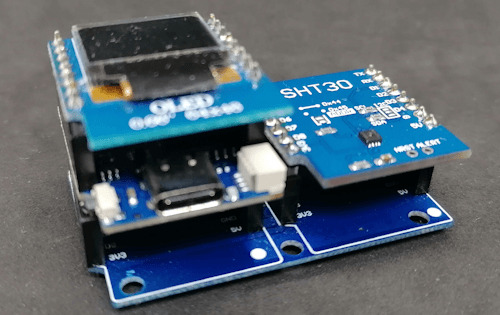
Wemos D1 Mini mit OLED Display & SHT30 Sensor
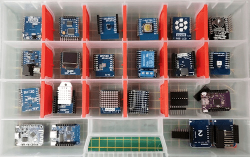
Shields für den Wemos D1 Mini Für den Wemos D1 Mini gibt es das Shield mit einem DS18B20, SHT30, DHT11 und DHT22 Sensor. Für diesen Beitrag verwende ich den Sensor SHT30. Das DS18B20 Sensor Shield ist am digitalen Pin D2 angeschlossen, an diesem liegt jedoch auch die I2C Schnittstelle an und diese benötigen wir für das OLED Display somit fällt dieses hier raus. Erhältliche Varianten des Wemos D1 Mini Den kleinen Mikrocontroller Wemos D1 Mini erhältst du derzeit in der Version 4.0 mit einem ESP8266. Wenn du jedoch mehr Leistung (CPU, Speicher) benötigst, dann kannst du auch auf eine Variante mit einem ESP32-S2 zurückgreifen. Beide Varianten kannst du für dieses Projekt verwenden!
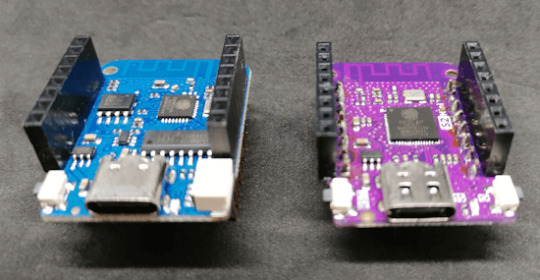
Wemos D1 Mini - Varianten Die beiden gezeigten Mikrocontroller habe ich dir bereits in separaten Beiträgen vorgestellt und einige Schaltungen präsentiert. - Vorstellung – Wemos D1 Mini V4 - Lolin S2 mini V1 im Test Technische Daten des Wemos D1 Mini Hier nun die technischen Daten des Wemos D1 Mini V4: Wemos D1 Mini V4Taktgeschwindigkeit80 / 160 MHzBetriebsspannung3.3 VAnzahl digitale Pins11Anzahl analoge Pins1Speicher4 MB SchnittstellenI²C, SPI, UARTUSB-AnschlussUSB-Typ-CVergleich der technischen Daten vom Wemos D1 Mini V4 & V3
Wie werden die Geräte miteinander interagieren?
Der Shelly verfügt über ein Relais, mit welchem man einen Verbraucher schalten kann. Der Shelly 1PM Mini Gen3 hat den Vorteil, dass dieser noch zusätzlich die Leistungsaufnahme messen kann. Mit dem Wemos D1 Mini wollen wir temperaturabhängig das Relais aktivieren / deaktivieren und auf dem OLED Display den Zustand anzeigen. Zusätzlich können wir auch die momentane Leistungsaufnahme anzeigen.

Der Vorteil dieser Schaltung liegt in ihrer einfachen Erweiterbarkeit. Zum Beispiel kannst du einen zusätzlichen Taster einbauen, um das Relais manuell ein- und auszuschalten, oder andere Sensoren integrieren. Mit einem IR Shield und der passenden Fernbedienung könntest du zudem weitere Geräte steuern und dir so ein kleines, intelligentes Dashboard schaffen.
Benötigte Ressourcen für dieses kleine Projekt
Schauen wir uns zunächst an, welche Ressourcen benötigt werden, um das kleine Projekt umzusetzen: - einen Shelly Mini - Shelly 1 Mini Gen* - Shelly 1PM Mini Gen3* - einen Wemos D1 Mini V4* - ein USB-C Datenkabel* - ein SHT30 Shield* - ein OLED Shield* - eine Dual Base Plate*
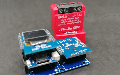
Shelly 1PM Mini Gen3 & Wemos D1 Mini Alternativ kannst du auch das Shield mit einem DHT11/DHT22 Sensor* verwenden. Hinweis von mir: Die mit einem Sternchen (*) markierten Links sind Affiliate-Links. Wenn du über diese Links einkaufst, erhalte ich eine kleine Provision, die dazu beiträgt, diesen Blog zu unterstützen. Der Preis für dich bleibt dabei unverändert. Vielen Dank für deine Unterstützung! Für den Shelly 1PM Mini Gen3 benötigst du noch ein Anschlusskabel, hier kommt es auf den Einsatzzweck an, in meinem Fall verwende ich ein 3x1,5mm² flexibles Kabel mit einem Schukostecker.
Programmieren des Wemos D1 Mini
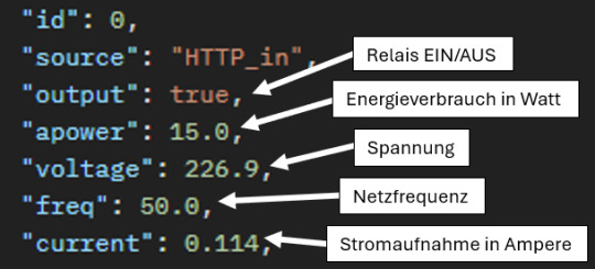
Den Shelly habe ich bereits mit der Cloud verbunden und damit Zugriff auf die Verbrauchsdaten und dem Relais. In diesem Abschnitt möchte ich dir gerne zeigen, wie der Wemos D1 Mini programmiert werden muss um das Relais zu steuern & die Verbrauchsdaten anzuzeigen. Programm - Temperaturabhängige Steuerung eines Shelly Minis mit dem Wemos D1 Mini & SHT30 SensorHerunterladen Schritt 1 - steuern des Relais via Postman Mit dem Tool Postman kann man Requests an Services senden und eine Antwort auswerten. Dabei kann der Request mit allen benötigten Informationen (Header, Body, Parameter etc.) bestückt werden. Das gute ist, dass man dazu erst einmal nichts programmieren muss, sondern man kann zunächst die URL und die benötigten Eigenschaften des Requests ermitteln. //aktivieren des Relais http://192.168.178.141/rpc/Switch.Set?id=0&on=true //deaktivieren des Relais http://192.168.178.141/rpc/Switch.Set?id=0&on=false In der offiziellen, englischen Dokumentation zur Schnittstelle von Shelly findest du alle Informationen, welche Daten du abgreifen kannst. Schritt 2 - Auslesen der momentanen Leistungsaufnahme am Shelly 1PM Mini Gen3 via Postman Wenn du wie ich den Shelly 1PM Mini Gen3 verwendest, dann kannst du vom angeschlossenen Verbraucher noch zusätzlich Daten ermitteln. Du kannst neben dem aktuellen Energieverbrauch in Watt, die Stromaufnahme in Ampere ermitteln. Vom Stromnetz selber können wir die Spannung und die Netzfrequenz ermitteln. http://192.168.178.141/rpc/Switch.GetStatus?id=0
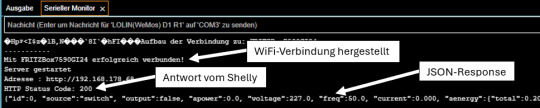
JSON Output von der Shelly API Schritt 3 - Auslesen der Daten am Wemos D1 Mini In der Arduino IDE kannst du dir Daten auf dem seriellen Monitor ausgeben lassen, das hat den Vorteil das wir nicht immer zwingend ein Display benötigen. Auf der seriellen Schnittstelle wollen wir zunächst die ermittelten Daten ausgeben. Schritt 3.1 - Aufbau einer WiFi-Verbindung Bevor wir etwas auslesen können, müssen wir eine WiFi-Verbindung zum lokalen Netzwerk herstellen. #include WiFiServer server(80); //Die Zugangsdaten zum WiFi-Netzwerk const char *ssid = "xxx"; const char *password = "xxx"; void initWifiModul() { Serial.println("Aufbau der Verbindung zu: " + String(ssid)); WiFi.begin(ssid, password); while (WiFi.status() != WL_CONNECTED) { delay(500); Serial.print("."); } Serial.println(); Serial.println("Mit " + String(ssid) + " erfolgreich verbunden!"); server.begin(); Serial.println("Server gestartet"); Serial.print("Adresse : http://"); Serial.println(WiFi.localIP()); } void setup() { Serial.begin(9600); initWifiModul(); } void loop() { // put your main code here, to run repeatedly: } Auf der seriellen Schnittstelle wird bei erfolg die IP-Adresse des Wemos ausgegeben. (Für diesen Beitrag nicht relevant.) Aufbau der Verbindung zu: FRITZBox7590GI24 ....... Mit FRITZBox7590GI24 erfolgreich verbunden! Server gestartet Adresse : http://192.168.178.68 Schritt 3.2 - Absenden eines HTTP-Request an den Shelly Zum Absenden der Daten benötigen wir einen HTTPClient, natürlich senden wir diesen Request nur ab wenn die WiFi-Verbindung besteht! #include String shellyServerAdress = "http://192.168.178.141/rpc/"; String shellyGetStatus = "Switch.GetStatus?id=0"; void sendHttpRequest(String url) { if (WiFi.status() == WL_CONNECTED) { WiFiClient client; HTTPClient http; http.begin(client, url.c_str()); int httpResponseCode = http.GET(); Serial.print("HTTP Status Code: "); Serial.println(httpResponseCode); String payload = http.getString(); Serial.println(payload); http.end(); } } Auf der seriellen Schnittstelle sehen wir nun neben dem Antwortcode vom Shelly (HTTP Status Code) noch zusätzlich den JSON Respond mit den gewünschten Daten.
Ausgabe der Daten eines Shelly 1PM Mini Gen3 auf dem seriellen Monitor Schritt 3.3 - Parsen des JSON Respond Um an die Daten im JSON Respond vom Shelly zu gelangen, müssen wir diesen jetzt parsen. Dafür benötigen wir die Bibliothek ArduinoJson. #include StaticJsonDocument json; char jsonResponse = ""; String relais = ""; String energieverbrauch = ""; String stromaufnahme = ""; String spannung = ""; String frequenz = ""; bool sendHttpRequest(String url) { if (WiFi.status() == WL_CONNECTED) { WiFiClient client; HTTPClient http; http.begin(client, url.c_str()); int httpResponseCode = http.GET(); Serial.print("HTTP Status Code: "); Serial.println(httpResponseCode); String payload = http.getString(); Serial.println(payload); payload.toCharArray(jsonResponse, sizeof(jsonResponse)); http.end(); return httpResponseCode == 200; } return false; } void printData(String text, String value, int index) { Serial.print(text); Serial.println(value); } void readData() { if (sendHttpRequest(shellyServerAdress + shellyGetStatus)) { DeserializationError error = deserializeJson(json, jsonResponse); if (error) { Serial.print(F("deserializeJson() failed: ")); Serial.println(error.f_str()); return; } Serial.println(); energieverbrauch = json + " W"; stromaufnahme = json + " A"; spannung = json + " V"; frequenz = json + " Hz"; relais = json == true ? "AN" : "AUS"; printData("Relais: ", relais, 0); printData("Energieverbrauch: ", energieverbrauch, 1); printData("Stromaufnahme: ", stromaufnahme, 2); printData("Spannung: ", spannung, 3); printData("Frequenz: ", frequenz, 4); } } Die Antwort vom Shelly (im JSON-Format) haben wir nun im Zugriff und können dort recht einfach auf die Daten zugreifen. Aufbau der Verbindung zu: FRITZBox7590GI24 ....... Mit FRITZBox7590GI24 erfolgreich verbunden! Server gestartet Adresse : http://192.168.178.68 HTTP Status Code: 200 {"id":0, "source":"switch", "output":true, "apower":14.5, "voltage":227.5, "freq":50.0, "current":0.112, "aenergy":{"total":2.884,"by_minute":,"minute_ts":1716113335}, "ret_aenergy":{"total":0.000,"by_minute":,"minute_ts":1716113335},"temperature":{"tC":55.5, "tF":131.9}} {"id":0, "source":"switch", "output":true, "apower":14.5, "voltage":227.5, "freq":50.0, "current":0.112, "aenergy":{"total":2.884,"by_minute":,"minute_ts":1716113335}, "ret_aenergy":{"total":0.000,"by_minute":,"minute_ts":1716113335},"temperature":{"tC":55.5, "tF":131.9}} Energieverbrauch: 14.500 W Stromaufnahme: 0.112 A Spannung: 227.500 V Frequenz: 50.000 Hz Schritt 4 - Anzeigen der Daten auf einem OLED Display Da wir die Daten vom Shelly nun ausgelesen haben, möchte ich dir zeigen wie diese auf einem OLED Display angezeigt werden. Für das ansteuern des OLED Displays am Wemos D1 Mini gibt es eine extra Bibliothek von Adafruit welche du bequem über den Bibliotheksverwalter installieren kannst.

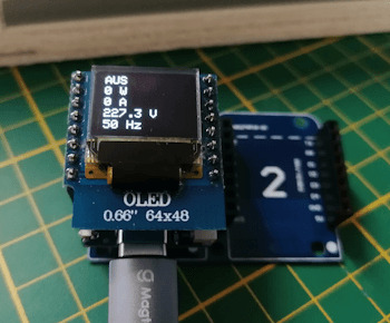
Bibliothek für das kleine OLED Display von Wemos Die Adresse des OLED Displays ist 0x3c, mit dem kleinen Programm aus dem Beitrag Arduino I2C-Scanner für ESP8266 & ESP32 anpassen: Eine Schritt-für-Schritt-Anleitung kannst du am ESP8266 nach geräten suchen. An LOLIN(WEMOS) D1 mini Pro was recognized! The microcontroller has 1 I2C Interfaces! SDA: 4, SCL: 5 Scanning... I2C device found at address 0x3c! End. Ich würde dir empfehlen eine zuvor installierte Version der Adafruit_SSD1306 zu deinstallieren damit eventuelle Probleme minimiert werden. #include #include #include #include #define OLED_RESET 0 // GPIO0 Adafruit_SSD1306 display(OLED_RESET); void setup() { Serial.begin(9600); initWifiModul(); display.begin(SSD1306_SWITCHCAPVCC, 0x3C); display.setTextSize(1); display.setTextColor(WHITE); } void printData(String text, String value, int index) { Serial.print(text); Serial.println(value); display.setCursor(0, index * 10); display.println(value); } void loop() { display.clearDisplay(); readData(); display.display(); delay(2000); } Die Daten werden nun nicht nur auf der seriellen Schnittstelle ausgegeben sondern auch auf dem OLED Display. Da das Display sehr klein ist, kann hier keine zusätzliche Bezeichnung hinzugefügt werden und es werden lediglich die Werte angezeigt.
Daten eines Shellys (deaktiviert)

Daten eines Shellys (aktiviert) Schritt 5 - Auslesen des Temperatursensors SHT30 Wie eigentlich ganz am Anfang erläutert soll das Relais temperaturabhängig gesteuert werden, dazu stecken wir nun das SHT30 Shield auf den freien Platz der Dual Base Plate.
Wemos D1 Mini mit OLED Display & SHT30 Sensor Man könnte auch die die Shields untereinander auf einem Breadboard stecken. Jedoch strahlt jedes elektrische Gerät eine wärme ab wie auch der WiFi Chip des Wemos D1 Mini und wenn der Sensor zu nah an diesem ist, werden die Werte stark beeinflußt. Technische Daten des SHT30 Sensors Den SHT30 Sensor habe ich dir bereits im Beitrag Wemos D1 mini Shield: SHT30 Temperatur und Luftfeuchtigkeit Sensor vorgestellt und gezeigt wie dieser programmiert wird. Hier nun die technischen Daten Sensors: - Betriebsspannung: 3V bis 5,5V DC - Betriebstemperatur -40 °C bis 125 °C - Schnittstelle: I2C (0x44 Standard / 0x45 über Lötpunkte) - Temperatur: -40 bis +125 °C (± 0,3 °C) - relative Luftfeuchtigkeit : 0 % bis 100 % (± 2 %) Bibliothek zum auslesen des Sensors Für den Sensor gibt es von Wemos eine Bibliothek welche du dir Read the full article
0 notes
Video
youtube
iot based agriculture monitoring pump on/off using arduino with Manual / Automatic | Smart Agriculture IoT Solution - IoT Sensors (Soil Moisture, Humidity, Temperature) | Smart Irrigation System | Arduino Uno | DHT11 | Humidity Sensor | Soil Moisture Sensor | Relay | GSM Based Motor Controller in Irrigation by Using Sensor's [ Soil Moisture Tank Water Level ] | SMS Based Remote Agriculture Pump ON/OFF Control and Notification | IOT BASED SUBMERSIBLE MOTOR PUMPS ON/OFF | IoT Based Agriculture Monitoring | pH | Moisture | Light | Irrigation | Rain | Temp | Humidity | IOT Based Agriculture Monitoring and Controlling System using Arduino Uno.***********************************************************If You Want To Purchase the Full Working Project KITMail Us: [email protected] Name Along With You-Tube Video LinkWe are Located at Telangana, Hyderabad, Boduppal. Project Changes also Made according to Student Requirementshttp://svsembedded.com/ https://www.svskits.in/ http://svsembedded.in/ http://www.svskit.com/M1: 91 9491535690 M2: 91 7842358459 We Will Send Working Model Project KIT through DTDC / DHL / Blue Dart / First Flight Courier ServiceWe Will Provide Project Soft Data through Google Drive1. Project Abstract / Synopsis 2. Project Related Datasheets of Each Component3. Project Sample Report / Documentation4. Project Kit Circuit / Schematic Diagram 5. Project Kit Working Software Code6. Project Related Software Compilers7. Project Related Sample PPT’s8. Project Kit Photos9. Project Kit Working Video linksLatest Projects with Year Wise YouTube video Links157 Projects https://svsembedded.com/ieee_2022.php135 Projects https://svsembedded.com/ieee_2021.php 151 Projects https://svsembedded.com/ieee_2020.php103 Projects https://svsembedded.com/ieee_2019.php61 Projects https://svsembedded.com/ieee_2018.php171 Projects https://svsembedded.com/ieee_2017.php170 Projects https://svsembedded.com/ieee_2016.php67 Projects https://svsembedded.com/ieee_2015.php55 Projects https://svsembedded.com/ieee_2014.php43 Projects https://svsembedded.com/ieee_2013.php1100 Projects https://www.svskit.com/2022/02/900-pr...***********************************************************Creating an IoT-based Smart Agriculture Monitoring System using Arduino can greatly improve the efficiency and productivity of farming. In this project, we'll use Arduino, various sensors, and an IoT platform like ThingSpeak or Adafruit IO to collect data and monitor the agricultural environment remotely. Here's a step-by-step guide to help you get started:Components Needed:1. Arduino (e.g., Arduino Uno or Arduino Mega)2. Sensors:• Soil Moisture Sensor• DHT22 or DHT11 Temperature and Humidity Sensor• Light Sensor (LDR)• Rainfall Sensor (optional)3. ESP8266 Wi-Fi module or ESP32 (for IoT connectivity)4. Relay module (for controlling irrigation systems)5. Power supply (solar or standard power source)6. Water pumps, valves, or actuators (for automated irrigation)7. Enclosure for outdoor installation (to protect electronics)8. Jumper wires, breadboard, and connectors9. Internet connectionProject Steps:1. Hardware Setup:• Connect the sensors and actuators to the Arduino using jumper wires.• Connect the ESP8266 or ESP32 to the Arduino using serial communication or I2C for data transfer.• Make sure all connections are secure and powered properly.2. Sensor Data Collection:• Read data from the soil moisture sensor to monitor soil moisture levels.• Use the DHT22/DHT11 sensor to measure temperature and humidity.• The light sensor can be used to monitor light intensity.• Optionally, include a rainfall sensor to measure precipitation.3. Arduino Programming:• Write Arduino code to read data from the sensors.• Implement control logic for irrigation systems based on the sensor data. For example, turn on/off water pumps or open/close valves.• Create a mechanism to send sensor data and control commands to the IoT platform via the ESP8266 or ESP32.4. IoT Integration:• Sign up for an IoT platform like ThingSpeak, Adafruit IO, or Ubidots.• Obtain the necessary credentials (API keys) to connect your Arduino to the platform.• Modify your Arduino code to send sensor data to the IoT platform periodically.• Set up dashboards and alerts on the IoT platform to visualize and analyze the data remotely.5. Remote Monitoring and Control:• Access your IoT platform's dashboard or mobile app to remotely monitor the agricultural conditions.• Implement automation rules and alerts to trigger actions (e.g., irrigation) based on specific conditions (e.g., low soil moisture).6. Power Supply:• Depending on your project's location, consider using solar power or a reliable power source to ensure continuous operation.
#youtube#IOT Based Smart Agriculture Monitoring Pump ON/OFF Control Using Arduino With Manual / Automatic https://www.youtube.com/watch?v=F3E0MiYCWpw
0 notes
Text
Let me introduce my current main WIP. It's not fandom related, it's for my model railroad, and it's not yet finished.
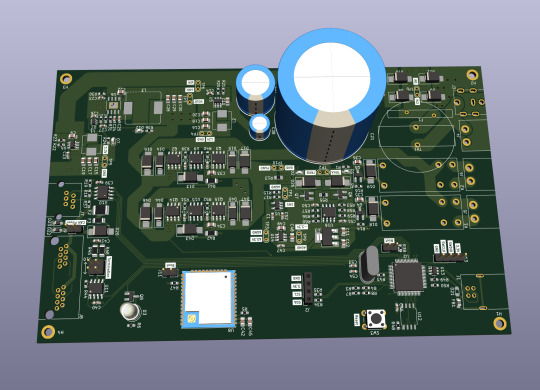
This is a rendering of a circuit board that I'm designing at the moment. It will be a DCC command station. My model railroad is run digitally, which means the tracks carry digital signals that tell each locomotive and switch individually how to run, which lights to turn and so on. The command station is the device that generates that. I have a number of different layouts, one of which has a good command station, one of which has a crappy old one, and the final one isn't even digital yet. So this will be the one that solves all issues for me, hopefully.
The design above isn't finished yet, and even the parts that are are not yet fully representative. The different capacitors are just there as options; some screen print overlaps; and some components (in particular all plugs and the relays that control the programming track) don't have 3D models so they don't show up.
Planned features:
Four layer board
10-25 V DC output, software controllable
Up to 5A output power, limited mainly by the main switching regulator.
Input 15-25V either AC or DC with polarity protection, selectable with some solder bridges (not yet in there). Optionally you can also bypass the main power regulator with another solder bridge (that I haven't added yet); useful in case you use e.g. a laptop power supply with a switchable voltage and don't need any regulation after that.
Railcom support
USB connection; not yet sure what for, but the main chip I'm using has USB support and I have some spare USB connectors here, so in it goes.
Speaking: The chip is an STM32L433RCT6P, chosen because I found it in stock at an electronics distributor. 64 kB RAM, 256 kB EEPROM, with support for an additional up to 256 MB externally (there's a spot for that on the board) and lots of fun extras that I don't technically need. It has an FPU! I don't need an FPU, but I will definitely do some floating point math computation on it just for fun.
Main external connection is WLAN using an ESP32 WROOM U module. I haven't decided on the housing, but I may go for extruded aluminum, so it's the U version that allows and requires an external antenna
It supports XBUS/XpressNet connections for old throttles from Lenz and Roco that I should probably throw away, but I paid good money for them, dang it.
It supports CAN for LCC / OpenLCB. I may not populate this part on all boards that I'm building, because I haven't actually decided whether I am interested. But the chip has CAN functionality built in, so why not.
There's an I2C connection to connect a cheap tiny OLED display for status messages.
Test points for all important signals (in particular the different internal voltage levels; yes, there is 3.3V, A3.3V and -3.3V and I need all of them).
Stuff still to add:
I will add pin headers (or space for pin headers anyway) for all the remaining pins on the STM32, and perhaps some on the ESP32, for future expansions.
Status LED and stop/go button on the front
Wire it all up, maybe move some stuff (mostly the STM32 around), which will cause all sorts of fun new routing issues.
Adjustments to make the jacks line up with the front panel once I've decided on a housing.
Features I'm not considering adding:
s88. I vaguely know what it is but I don't have any devices like that, and if that ever changed I could probably build (or perhaps buy) a converter that connects them via CAN.
Other buses like LocoNet.
Ethernet. I don't need it and it's actually more expensive than WLAN in this day and age.
In terms of software, I'm planning to use DCC-Ex on it. The whole project actually started out as a DCC-Ex shield, but once I realised that this wouldn't fit, I decided to make it standalone. Now, DCC-Ex is designed for Arduino, not STM32, and it doesn't support XpressNet, nor OpenLCB, nor Railcom, and their Wifi protocol is pretty weird and annoying which will be an issue (I'm planning to write my own control app for iPhone for it), so I'll probably change that or just replace it with the z21 one… so really, the software will not look a lot like DCC-Ex once I'm done with it.
Will this all work? I have honestly no idea. I mean, I'm fairly confident, I'd have given up on this long ago otherwise, but I have no guarantees either way until I've spent a lot of money on components and circuit boards and start soldering. Turns out doing it this way is not really cheaper than just buying a half-way decent one. That's what makes it exciting, though!
If it does work, obviously this will be released as open source. But it's still going to be a few days (more realistically weeks) before it's even ready to order the parts, and then a lot of soldering (current BOM stands at 194 actual components), and then a lot of software development before it's ready for that.
5 notes
·
View notes
Video
instagram
* 🇧🇷 Rele Board 8 com módulo e Display I2C. Controlando 8 reles e o display com apenas dois pinos (I2C) ----------------------------- youtube.com/ProjetosEletronicos ----------------------------- 🇺🇸 Relay Board 8 I2c with module and I2C Display. Controlling 8 relay and the display with only two pins (I2C) ----------------------------- #releboard8 #i2c #display #Waldunano #arduino #arduinouno #arduinonano #makers #maker #diy #geek #projeto #protótipo #prototype #engenharia #engineering #hardware #walproj #projetosmaker #projetoseletronicos (em Projetos Eletronicos) https://www.instagram.com/p/CDuxOGdBea1/?igshid=91ed7urqnb86
#releboard8#i2c#display#waldunano#arduino#arduinouno#arduinonano#makers#maker#diy#geek#projeto#protótipo#prototype#engenharia#engineering#hardware#walproj#projetosmaker#projetoseletronicos
2 notes
·
View notes
Video
instagram
Posted @withrepost • @easytronic3795 Android Control HOME APPLINCES Follow @easytronic3795 for more related project AND ANY HELP U CAN DM ME Check_out my new page @easytronic_snapshot Arduino uno Android AAP 4 channel Relay module I2C lcd module LCD ( 16*2) 12 VOLT DC FAN HC-05 BLUETOOTH AC COLOUR BULB BREADBOARD JUMPER WIRE Tag u friend U can subscribe my youtube channel for explained video ( EASYTRONICS ) https://m.youtube.com/watch?v=W7l80lYLcAY&t=13 #electrical #iot #electricalengineer #arduino #ai #electric #automation #electronic #electronica #internetofthings #electronics #pcbuild #engineer #automation #programmer #pcbuilds #programming #innovation #circuit #adafruit #raspberrypi #device #nodemcu #techno #arduinouno #robotics #arduinoproject #coder #robots #robot (at Busan, South Korea) https://www.instagram.com/p/BzX5Iafl3FB/?igshid=1mubhzas87yxz
#electrical#iot#electricalengineer#arduino#ai#electric#automation#electronic#electronica#internetofthings#electronics#pcbuild#engineer#programmer#pcbuilds#programming#innovation#circuit#adafruit#raspberrypi#device#nodemcu#techno#arduinouno#robotics#arduinoproject#coder#robots#robot
2 notes
·
View notes
Text
Sensor
What are Sensors?
The sensor may be defined as a machine, module, subsystem, or device whose purpose is to detect changes and events in the environment. The information regarding these changes is further sent to various other electronics mostly comprising of a computer processor. A sensor is always used along with an electronic device.
Sensors are used in various everyday objects comprising of lamps with touch sensation which dim and light up by touching the base and touch-sensitive elevator buttons. With time, there have been advances in micromachinery and microcontroller platforms that are easy to use.
Read More
With time, the uses of sensors have increased beyond pressure or flow measurement and traditional fields of temperature. Analog sensors such as force-sensing resistors and potentiometers are widely in use even today.
The applications comprise airplanes and aerospace, medicine, cars, manufacturing and machinery, robotics, and various other aspects related to daily life. There are various sensors available that are used for measuring the physical and chemical properties of materials.
Now let’s read about the classification of sensors after which we will go through the types of sensors and how sensors work.
Classification of Sensors
Sensors are classified on the basis of the output signal, physical parameters measured by them, and various other points. Sensors on the basis of the output signal are classified into analog and digital output sensors.
The output given by the sensors in the case of analog output sensors is an analog voltage that can be measured and used for determining the required physical parameter. This is done by making use of the sensor’s transfer function. It may be resistive, capacitive, or anything which is analog.
The digital data which can be read via parallel or serial communication buses is the output of digital output sensors. The format for the data, in this case, is demonstrated in the sensor’s datasheet. An accelerometer sensor is an example of a digital sensor that is used for sending the output data by using the I2C two-wire bus.
The sensors are further classified on the basis of physical parameters; these types may be used for measuring anything. The most common sensors are tilt sensor, magnetic sensor, cameras, color sensor, pressure sensor, fingerprint sensor, current sensor, light sensor, etc.
Different Types of Sensors with Their Applications
In daily life, it has become our habit to implement various types of sensors frequently in the power systems comprising of load control systems, electrical and electronics appliances, and industrial and home automation. All types of sensors are further divided into analog and digital sensors.
However, there are few types of sensors that are used in electronic applications such as pressure sensors, touch sensors, IR sensors, ultrasonic sensors, temperature sensors, proximity sensors, and so on.
Temperature Sensors:
Temperature is the commonly measured environmental quantity for various reasons. There are different types of temperature sensors that are used for measuring temperature such as thermistors, resistance temperature detectors, thermocouples, semiconductor temperature sensors, and so on.
On the basis of requirements, various types of sensors are used for the purpose of measuring temperature in different applications. A simple temperature sensor with a circuit may be used for switching the load on and off at a specific temperature.
Read More
This temperature is detected by the temperature sensor, in these cases, a thermistor is put to use. The temperature sensor circuit comprises a thermistor, transistor, relay, and battery. The temperature sensor activates the relay by detecting the required temperature.
The relay switches on the load that is connected to it which can be AC or DC. This circuit may be further utilized for the purpose of controlling the fan on the basis of temperature. Primarily, this type of sensor may be further classified into various other types such as digital temperature sensors, thermistors, and so on.
IR Sensors:
The small photo chips comprising of photocells that are used for detecting and emitting infrared light are termed IR sensors. These sensors are most commonly used for the purpose of designing remote-control technology.
These sensors may be used for detecting various obstacles of the robotic vehicle and controlling the direction of the same. There are different types of sensors that might be used for the detection of infrared lights.
A simple example of an IR sensor circuit that we use in our day-to-day life is a TV remote control. It comprises IR receiver circuits and IR emitter circuits that may be designed. The IR emitter circuit is used as a remote by the user for the purpose of emitting infrared light.
This infrared light is transmitted or sent to the IR receiver circuit which interfaces to the devices such as IR remote-controlled robots or a TV. These sensors are further used for designing television remote controls.
A TV remote is an example of a simple IR sensor-based electronics project which is used for the purpose of controlling a robotic vehicle in remote areas by using IR or TV remote. This type of TV remote is being utilized for sending commands to the robotic vehicle.
Ultrasonic Sensor:
An ultrasonic sensor or transceiver is a transducer that works on the principle alike radar or sonar and is known for estimating the attributes of the target by interpreting. These sensors are classified as active and passive ultrasonic sensors and maybe differentiated on their working.
The active ultrasonic sensors are known for generating high-frequency sound waves that are received back by the ultrasonic sensor for the evaluation of echo. The time interval taken for receiving and transmitting the echo helps in the determination of the distance to an object.
However, the passive ultrasonic sensors are merely used for the detection of ultrasonic noise whose presence can be found in specific conditions. When it comes to the practical application of an ultrasonic sensor with a circuit, it may also be used as an ultrasonic distance sensor circuit.
Touch Sensor:
The switches that are activated by touch may be said to have touch sensors. These sensors are classified into different types on the basis of their touch-type such as piezo touch switch, capacitance touch switch, and resistance touch switch.
For the purpose of controlling the load, a touch-sensitive load is designed. The touch-controlled load switch which is touch sensor principle-based comprises various blocks such as touch sensor plate, load, relay, and power supply block.
Proximity Sensor:
The proximity sensor is a type of IoT sensor in which the existence and non-existence of the surrounding objects are identified. After this, the detected signal is converted into a form that the user understands.
This type of sensor is mainly applied in the retail domain where any movement is found out and an association is present between the consumer and product. The users are provided with quick notifications related to exclusive offers and discount updates of the products in which they are interested.
Chemical Sensor:
A chemical sensor helps in determining various kinds of changes in liquid and for detecting the air chemical variations. These are mainly put to use in bigger cities and towns as it is important to look after the changes for providing safety to the people.
This type of sensor is essentially implemented in commercially atmospheric observation. It is used for processing management which may comprise of fortuitously or intentionally evolved chemicals, radioactive exposure, pharmaceutical industries, and reusable operations in space stations.
The most commonly used chemical sensors include chemical FET, electrochemical gas type, chemi resistor, non-dispersive IR, zinc oxide nanorod, and fluorescent chloride type.
Gas Sensor:
Gas sensors are similar to chemical sensors but are specially implemented for observing modifications in the quality of air. This is done to find out which types of gases are present in it. This sensor is being used in multiple domains such as health, manufacturing, agriculture, for supervision of gas in coal industries, chemical laboratory investigations, etc.
Some of the gas sensors that have been put to use include hydrogen type, hygrometer, carbon-dioxide sensor, ozone monitoring type, air pollution type, gas detection type, etc.
Humidity Sensors:
Humidity is used for defining the vapor present in the atmosphere or in gaseous substances. Humidity sensors are used as temperature sensors as the manufacturing operations require similar operating conditions. By measuring humidity, it can be ensured that the complete procedure will pass away easily.
In case of modification, immediate action can be taken as these sensors are known for quickly identifying the variations. There are numerous domains in which these are used such as ventilators, residential and commercial use for heating purposes, etc. Some other domains include meteorology, greenhouses, automobile, painting, coating industries, and hospitals.
Acceleration Sensor:
An acceleration sensor is used for calculating the acceleration and angular values. The accelerometer is primarily used for calculating acceleration. There are two types of forces that create an impact on the accelerometer; these are static force and dynamic force.
Read More
These sensors are present in numerous configurations and their type of selection is dependent on the industry’s requirement. There are few parameters that are required to be checked before selecting the sensors such as total number of axes, bandwidth, sensitivity, type of outputs, etc.
Sound Sensor:
Sound sensors can generally be identified as the microphone devices that are used for delivering the corresponding level of voltage and sound on the basis of the sound level detection. By implementing the sound sensor, a small robot may be manufactured for navigation on the basis of sound received.
In comparison to light sensors, the design process of sound sensors is complicated. The reason being the delivery of minimal voltage difference by them. This is further to be amplified for providing voltage variation that is measurable.
Various other sensors include a light sensor, tactile sensors, force sensors, etc. The types of sensors used in building include motion detection sensors, camera sensors, gas sensors, smoke and fire detection sensors, electric voltage and current sensors, and temperature sensors.
Uses of Sensors
If we look around carefully, sensors are used in many products that we use in our day-to-day life. Sensors are used in various industries comprising automotive, medical, aerospace, defense, and agriculture.
Position sensors are used for the purpose of measuring movement, displacement, and position and maybe rotary or linear. These are used for controlling the throttle, measuring wind direction, positioning the ramp and bridge, simulating flights, and steering angle measurement.
Pressure sensors are being used for measuring pressure and can be a differential, gauge, or absolute. The most common types of pressure sensors that are used comprise transducers which are also known as pressure switches or pressure transmitters.
Some of the areas of pressure sensor application are oil pressure, tire pressure, vehicle braking systems, oil pressure, fans, filters, and diesel and engines applications. The force sensors also known as load cells or weight sensors are used for weighing applications in scales.
The weight sensors are known for giving the exact weight measurement by measuring the amount of force that is being applied. The load sensors are used in counting scales, hopper scales, platform scales, tank weighing, and on-boarding weighing.
Temperature sensors are put to use when it comes to monitoring and measuring the temperature of liquid, solid, and gas. It is the most commonly used sensor in homes and it is used in various shapes and sizes for serving different purposes.
This type of sensor is used in motors, surface plates, computers, industrial equipment, electrical radiators, exhaust gas monitoring, and home appliances. Sensors are highly beneficial and are used in various equipment used in our daily lives.
Applications of Digital Sensors
Digital sensors are the electrochemical sensors or electronic sensors in which the transmission and conversion of data take place. Digital sensors are known to have overcome the drawbacks present in analog sensors and have slowly begun to replace them.
Digital sensors are of different types such as digital accelerometers and digital temperature sensors. A digital accelerometer is known for generating variable frequency square wave output termed pulse-width modulation. In this, the readings are taken at a fixed rate by the pulse width modulated accelerometer.
A digital temperature sensor is known for providing device temperature with 9-bit temperature readings. It is known for acting as a thermostat with the presence of three thermal alarm outputs. It is being considered as a digital temperature control system that uses digital temperature sensors.
This control system has various advantages and provides accurate results in comparison to the analog temperature control system. A digital temperature control system is capable of providing a temperature display and switches off when the temperature exceeds a set point.
Real-time Application Sensor
Sensors get information from the environment and transfer it to the computer. The system transfers the input to the needed output and displays it to the user.
Civilians and military aircraft use them in one way or another. They have the AutoPilot system application where the aircraft controls its flight by itself when all the conditions are stable. This system has several sensors to measure the height, pressure, light, humidity and saves the information in the system. This information is compared with the preset information, which provides a stable condition. If both the information is the same, the computer sends information to various parts of the aircraft such as wings, rudders, stabilizers. Then the autopilot system takes control of the aircraft until found otherwise. All these are important in this system.
Another application is using the wireless network in different industries. Various sensors are used in different places to collect various data related to different fields. This data is used in medical, engineering and agricultural fields.
Read More
When the fire is detected inside the industry, the smoke detector provides a signal to the light sensor. The light sensor produces light which senses the alarm system implemented inside the industry. This produces the alarm in the industry and thus alerts security and employees.
Fitbit, the activity tracker, tracks the activities of the users by sensing the movements such as walking, running, sleeping and other motions. This helps in tracking the health of the user.
They are helpful to the people to detect smoke, to know the health, to prevent accidents. It can be used to detect a missing person as well as the presence of water on the moon.
Pros and Cons of Different Sensors
Now let’s go through the pros of different sensors. When it comes to a touch sensor, the axle hole present in the sensor area may be used for creating its own bumper. The color sensor is known for detecting color, avoiding ambient light, and following lines.
The gyro sensor can be used for accurately turning and measuring the robot turning. An infrared sensor helps in finding the beacon and remote receiver. It is known for working and helping in measuring the proximity accurately.
An ultrasonic sensor measures in and cm and provides accurate distance measurement and wall following. These were the pros of different sensors, let’s know the cons of different sensors. The con in the case of a touch sensor is that the object must touch the sensor’s red part and its sensor area is small.
Read More
The color sensor is known to be reliable only when it is at a close range and the light color that it detects is white. In the case of a gyro sensor, the robot is required to be still when it is plugged. It can be unreliable and touch many times.
The other cons of different sensors include the sound of ultrasonic which may interfere with the sensor. The infrared sensor is not allowed in FLL and is not measured in cm or in. Hope you have received a great insight regarding sensors through this blog.
1 note
·
View note
Text
Quality Arduino Alternative for Industrial Use
For the best quality Industrial Application of Arduino hurry up to visit Norvi. This is a leading platform offering a wide range of products available at affordable prices. Invest in Industrial Application of Arduino and you will certainly get the best value for your money. Other than real-time acquisition and pushing to an IoT platform, data loggers are one method of keeping track of values and analyzing. The industrial world is full of various types of data loggers. These include the following types:
USB loggers which are used for Short-term trend logging with manual offload
Bluetooth (BLE) Loggers with Wireless data access via mobile devices
Web-based Systems with Long-range wireless internet access
Wireless Sensors with Short-range centralized data collection
With the ESP32 based NORVI IIOT, you can build any of those solutions in the simplest way possible. You can invest in Arduino Wifi Data Logger and see that costs can also be kept lower compared to other data-loggers. NORVI IIOT ESP32 Data-logger with Web-access is the best choice offering almost all the acquisition types you need to build the Real-time data logger with web access. It includes digital inputs (As counters or ON-OFF status detection), 0-10V Voltage Analog Inputs, 4-20 mA Current Analog Inputs, temperature inputs, load cell inputs, RS-485 communication interface, and 12C communication interface. As NORVI IIOT supports all the above input types which means you have access to the real-word parameters. The next step is storing them with time stamp. Believe it or not, NORVI IIOT AE04 range is an amazing data-logger with Web access. To keep track of time and micro-SD card support providing storage facility for the data, you can also take advantage of DS3231 Real Time Clock (RTC). You can also store the needed data in microSD card in CSV format or in a database with SQLite3 library.
Due to ESP32 based NORVI IIOT, it is also possible to implement wireless access for the logged data and real-time data. You can access or view the data by using WiFi if you combine few libraries of ESP32 Arduino. There are several examples for ESP32 to work as a datalogger and Web-interface for real-time data.
If you want Arduino Alternative for Industrial Use you can rely on Norvi again and again. Remember that if you have access to efficient hardware, you will be able to finish your project in the fastest possible time. GPIO pins are isolated and connected to the relays and inputs. You can control relays and inputs via GPIO. You will be provided with LED Indicators for Inputs, Outputs and Seria, Arduino libraries for reading analog inputs and driving OLED Display, Expansion port with UART, SPI, I2C, and 2 GPIO which lets you access external devices or modules. You can also enjoy USB Connection as a usual Arduino board to connect with the Arduino IDE. What’s more, MicroSD card support is also provided. This means that you can add a micro SD card for expanding its capacity, for applications like dataloggers. Just order this Arduino Alternative for Industrial Use and be sure to enjoy these benefits.
0 notes
Text
Arduino MKR IoT Carrier: Control what you want, how you want to!
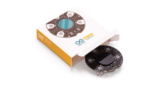
By popular demand, we are pleased to announce that it’s now possible to buy the Arduino MKR IoT Carrier. Originally forming a key part of the Arduino Oplá IoT Kit, we’ve responded to our community to make the carrier available on it’s own, thus enabling you to benefit from having a bunch of sensors, actuators and a display all featured on the one board — making it quicker and easier to take your IoT projects to the next level.
Featuring a large set of built-in sensors and actuators as well as a useful color display, the carrier lets you focus on prototyping your IoT ideas right away by saving on the hassle of wiring and soldering these components.
The carrier can become a WiFi, LoRa, NB-IoT or GSM-compatible device by seamlessly connecting to any MKR family board. Building a user interface for these boards is easy with the embedded color OLED screen, five capacitive touch buttons, and the five RGB LEDs. The integrated sensors (temperature, humidity, pressure, RGBC light, gesture and proximity) allow you to map the environment around the carrier, and should you need to capture any other data there are over 100 additional Grove sensors that can easily be connected directly to the carrier.
Here’s are quick demo of the carrier’s capabilities! (Special shout out to Mirko Pacioni and Fill Connesso for creating this demo.)
youtube
Capture and store all the data locally on an SD card, or connect your MKR family board to the IoT Cloud for real-time data captured, storage, and visualization.

The MKR IoT Carrier features:
Round OLED display
Five RGB LEDs
Five capacitive touch buttons
On-board sensors (temperature, humidity, pressure, RGBC light, gesture and proximity)
Buzzer
IMU (Three-axis accelerometer sensor and three-axis gyroscope sensor)
Two 24V relays
MicroSD card holder (SD card not included)
Plug-and-play Grove connectors for external sensors — two analog and one digital (I2C)
18650 Li-ion rechargeable battery holder (battery not included)

The MKR IoT Carrier is now available to purchase from the Arduino online store for €48 / $57.60 — find infinite possibilities for all your IoT projects
Interested in learning how to build IoT projects, then we have the perfect choice of kits for you, both featuring the MKR IoT Carrier. The Arduino Explore IoT Kit is the ideal kit to learn about the Internet of Things and what you can do with it, while the Arduino Oplá IoT Kit is great for experiencing the benefits of IoT at home or in the office with eight out-of-the-box IoT projects controlled on the Arduino IoT Cloud.
Arduino MKR IoT Carrier: Control what you want, how you want to! was originally published on PlanetArduino
0 notes
Text
ESP32, How to Access TelegramBot Relay/Led Control
ESP32, How to Access TelegramBot Relay/Led Control
Hello Full Child Friend. on this occasion I will write an article about ESP32, How to Access TelegramBot Relay/Led Control. Previous Tutorial Read Also : ESP32, How to Access I2C 16×2 LCD previously I've written many articles about Telegram Bot with ESP8266, now we will try to use ESP32 to control Relay with Telegram keyword : Bot Telegram ESP32 ESP32 TelegramBot Learn ESP32 Learn ESP32…

View On WordPress
0 notes
Text
Low Power Bridges Market Analysis, Size, Application Analysis, Regional Outlook, Competitive Strategies And Forecasts 2027
Low-power Bridges with Motor Control Offer Power Savings for Consumers in Wearable Devices
The wearable devices market has been experiencing explosive growth during the past couple of years. The demand for low-voltage applications in wearable devices has triggered growth for the low-power bridges market. Companies in the low-power bridges market space are innovating in motor driver ICs (integrated circuits) of wearable devices. Increasing consumer awareness about health and fitness has propelled market players to develop consumer-centric fitness trackers, smartwatches, and sports equipment.
Companies in the low-power bridges market are innovating new motor driver ICs of wearable devices. Low-voltage innovations are increasingly meeting the consumer need for efficient battery-powered devices that are portable. Manufacturers in the low-power bridges landscape are increasing R&D to gain excellence in motor control of wearable devices. Growing demand for compact-sized devices has led to the development of motor controls packed with tiny ICs. Companies are focusing on enhancing user experience with improvements in the quality of wearable devices. Low-input voltage in devices offers power savings for consumers, which adds value to the newly introduced devices with an extended battery lifetime.
Request a sample to get extensive insights into the Low-power Bridges Market
I2C V/S SPI: Which is better for Your Company?
I2C (inter-integrated circuits) and SPI (serial to peripheral interface) protocols offer unique strengths and weaknesses for companies in the low-power bridges market. SPIs are being increasingly used in IC controllers and peripherals to communicate with each other. On the other hand, I2C is gaining increasing popularity as a standardized serial communication protocol. This protocol is being increasingly used for communication between chips on a PCB (printed circuit board).
However, SPI is not an official standard for deployment in many devices. On the other hand, I2C is popular for communication between components. However, with technological advancements, faster data transmission modes are pervasively replacing I2C. Perhaps these limitations pose a challenge for manufacturers in the low-power bridges market, who find it difficult to develop wearable devices with secure contactless applications.
Despite the limitations, manufacturers in the low-power bridges ecosystem are learning the technicalities of SPI and I2C with their implementations between master controllers and slave peripherals for better product development.
Companies Innovating in Photorelays for Development of Compact-sized Thermostats
Tried and tested technology acts as a reliable strategy for companies in the low-power bridges market. This strategy is being used by them to develop photorelays with low voltage circuits. Companies in the low-power bridges market are expanding their production capabilities to develop photorelays that are increasingly replacing conventional mechanical relays in thermostat designs. They are capitalizing on the demand for sleeker-looking devices, which is possible with the help of photorelays.
Design engineers in the low-power bridges landscape are on the lookout for compact alternatives, catering to the development of aesthetically-pleasant thermostats. Companies are increasing R&D to develop innovative photorelays that are a better choice for design engineers, since they overcome the limitations of mechanical relays. Another factor that is driving the adoption of photorelays is that, they can be easily integrated with microcontrollers and other low-voltage control circuitry, sans the need for separate power supply.
Turnkey Embedded Systems Create Incremental Opportunities in Mission-critical Applications
Any device with an in-built digital interface suitable for computing is an embedded system. Low power consumption of embedded systems is gaining widespread acceptance in the automotive, consumer electronics, and home appliance sectors. Likewise, cell phones contribute to the highest revenue in the low-power bridges market, along with high-value growth potential by reaching a value of ~US$ 500 million by the end of 2027.
Embedded systems are almost omnipresent in all electronic devices that have built-in embedded software. Hence, manufacturers are increasing the efficacy of low-power bridges in embedded systems. However, challenges in embedded software development is one of the many reasons for the sluggish CAGR of ~3% for the low-power bridges market. The issue of stability in embedded systems poses a challenge for manufacturers, owing to their unexpected functionality which is inadmissible. To overcome this issue, manufacturers in the low-power bridges space are onboarding skilled employees that quickly adapt to technological advancements in the highly competitive landscape. Companies are fetching incremental opportunities in mission-critical applications such as industrial automation equipment and missile guidance systems with the help of improved embedded systems.
Stuck in a neck-to-neck competition with other brands? Request a custom report on Low-power Bridges Market
Analysts’ Viewpoint
The low-power bridges market is consolidated in nature; only four major players dominating the landscape with an expected market share of ~60% throughout the forecast period. Companies are investing in Ethernet solutions for in-vehicle infotainment systems and telematics in the automotive environment. They are fostering innovation in embedded systems, right from smart watches to smart houses and ubiquitous control systems. However, the compatibility and integrity of embedded systems is posing a challenge for manufacturers in the IoT landscape. Thus, companies should gain expertise in hands-on experience for deploying embedded systems in IoT applications. They should focus on the development of new wearable devices suitable with smartphones and healthcare equipment.
Global Low-power Bridges Market: Overview
According to Transparency Market Research’s latest research report on the global low-power bridges market for the historical period of 2017–2018 and the forecast period of 2019–2027, rise in the need for early target tracking, increase in the demand for low-power bridges, and benefits offered by low-power bridges when used in various devices are expected to boost the global low-power bridges market during the forecast period.
In terms of revenue, the global low-power bridges market is estimated to reach a value of ~US$ 1 Bn by 2027, expanding at a CAGR of ~3% during the forecast period.
Various Benefits Offered by Low-power Bridges: Key Driver of Low-power Bridges Market
Ongoing advancements in low-power bridges offer opportunities to simplify the design process and provide options and flexibility that reduce the part count in electronic products; save processor resources; and increase flexibility easily by providing built-in controls that previously required complex software and hardware.
I2C and SPI are two widely-used bus protocols in embedded systems nowadays. The I2C bus has a minimum requirement for pin count, and as such, has a smaller footprint on board. The SPI bus provides a synchronized serial link with performance within MHz range.
As embedded systems are required to support an increasing number of protocols and interfaces, bridge designs targeting popular protocols provide solutions to reduce the time and cost required for development.
Growing adoption of IoT worldwide is anticipated to raise the need for low-power consumption and high performance, thereby boosting the demand for low-power bridges.
In addition to sensors, high-resolution cameras are key enablers of IoT devices. The challenge for IoT designers is to find a solution that delivers low-power consumption and high performance, while meeting cost constraints. A low-power bridge is a proven interface in the mobile sector, and due to its successful implementation, it is utilized in new applications such as IoT and virtual/augmented reality devices.
Related Reports Press-Release –
https://www.prnewswire.com/news-releases/bra-market-is-expected-to-reach-us-34-914-7-million-by-2026-noted-tmr-300802037.html
https://www.prnewswire.com/news-releases/1-4x-growth-to-be-witnessed-in-revenue-in-luxury-folding-carton-market-from-2019-to-2027–notes-transparency-market-research-301062529.html
https://www.prnewswire.com/news-releases/text-analytics-market-to-expand-at-a-striking-17-6-cagr-with-booming-it-and-telecom-sector—tmr-300856977.html
About Us
Transparency Market Research (TMR) is a market intelligence company, providing global business information reports and services. Our exclusive blend of quantitative forecasting and trends analysis provides forward-looking insight for thousands of decision makers. TMR’s experienced team of Analysts, Researchers, and Consultants, use proprietary data sources and various tools and techniques to gather and analyze information.
Our data repository is continuously updated and revised by a team of research experts, so that it always reflects the latest trends and information. With a broad research and analysis capability, Transparency Market Research employs rigorous primary and secondary research techniques in developing distinctive data sets and research material for business reports.
Contact
90 State Street, Suite 700
Albany, NY 12207
Tel: +1-518-618-1030
USA – Canada
Email: [email protected]
Website: https://www.transparencymarketresearch.com
0 notes
Text
Control FAN Speed and LIGHT using TV Remote
youtube
Control FAN and LIGHT using TV remote | Control of Lights + Fan using Wi-fi and Bluetooth | Arduino Based Home Automation using TV Remote | IR Remote Controlled Home Automation Project using Arduino | Smart Home Automation Using Arduino and Infrared Remote. ****************************************************************** If You Want To Purchase the Full Project or Software Code Mail Us: [email protected] Title Name Along With You-Tube Video Link Project Changes also Made according to Student Requirements http://svsembedded.com/ è https://www.svskits.in/ M1: +91 9491535690 è M2: +91 7842358459 ****************************************************************** 1. Control FAN and LIGHT using TV remote, 2. Control your LEDs with your TV remote - Arduino IR Tutorial, 3. Using IR Remote Controls with the Arduino, 4. HACKED: TV Remote becomes an RF Remote || nRF24L01, 5. Use Infrared sensor & IR Remote control on Arduino – Tutorial, 6. EEVblog - IR Remote Control Arduino Protocol Tutorial, 7. How to make voice control home automation system using Arduino, 8. Control your room lights and fan using TV remote, 9. How to make ir remote control home automation using Arduino multiple channel, 10. Infrared (IR) Remote control. Arduino, 11. Control your Infrared Devices from the Internet with IR Remote (Arduino / Raspberry Pi Compatible), 12. Control a Stepper Motor using an IR Remote and Arduino UNO – Tutorial, 13. Arduino Controlled using TV or IR Remote - TV/DVD Remote Decode, 14. Fast Hacks - Clone Infrared Signals with Arduino, 15. How to hack any IR Remote using Arduino, 16. Dish Antenna Position Controller Using TV Remote, 17. Control any Electronics with a TV Remote | Arduino IR Tutorial, 18. Arduino Controlling LEGO Power Functions Motor Part 2: IR Remote Control, 19. Arduino Home Automation: Control Your TV, Air Conditioner, Fan, etc. with an Infrared Transmitter, 20. How to Decode any IR remote |TV,DVD,AC any other, 21. Sinhala Arduino Tutorial 08 - IR Remote Controller (TV remote), 22. How to Control Arduino Robot Car with TV Remote Control | Infrared Remote IR, 23. Using IR Signals to Control TV, 24. ARDUINO: IR REMOTE CONTROL OF LEDS, 25. 5-min Tutorials: Arduino IR Remote & Receiver, 26. Remote Controlled AC Fan Regulator using Arduino, 27. Arduino - Control LED's with IR Remote Control, 28. Tutorial on Infrared sensor TSOP 1738 with Arduino | Connections & Coding, 29. ESP8266 As A WiFi Controlled Universal Remote, 30. Android Remote Control TV or other IR devices, 31. Arduino IR Remote Control Do it yourself, 32. Remote control Fan- IR remote control Circuit using IC 555 Timer, 33. Arduino Project: MP3 player with IR remote control DIY, 34. Apple Remote as a Universal Remote Control using Arduino [Anything Arduino], 35. Bluetooth & IR Remote - Elegoo Arduino Smart Robot Car Part 2, 36. How to Decode IR Remote Control Signals, 37. Using a VS1838B IR Sensor to Remotely Control an Arduino Project, 38. Arduino control LEDS with IR remote, 39. IR Remote Control For Home Appliances Using Arduino Multiple Channel, 40. Arduino turn off lights with TV remote - 120V relay, 41. App Inventor 2 - Arduino + Android Tv remote, 42. Fast Hacks -17 - Remote Control your Computer using Arduino, 43. [Basic]Arduino IR remote Control: Control LED using TV Remote, 44. TUTORIAL: How to Quickly Setup Infrared IR Remote Control Sensor with ESP32 - Arduino - ESP8266, 45. How to use Arduino as TV Remote Controller with Infrared, 46. Arduino IR Remote Control, 47. Controlling Servo motor with IR Remote using Arduino code, 48. Arduino Controlled Remote Door Opener using Servo Motor, 49. Control remote universal: Control to TV con Arduino, 50. Control LED with IR Remote Control + Arduino, 51. ESP 8266 NodeMCU RGB LED Strip controlled by a web server remote, 52. Make your own TV remote controlled car| Super easy Arduino tutorial, 53. IR Remote Control For Home Appliances Using Arduino Multiple Channel, 54. Magnetic Loop Antenna controlled by Arduino and infrared, 55. Home Automation With TV Remote in HINDI, 56. Tutorial: Controlling an Arduino with an Infrared (IR) Remote Control, 57. HOW TO MAKE A ARDUINO UNIVERSAL REMOTE CONTROLLER, 58. How to Control Your TV With an ARDUINO, 59. Using Infrared sensor & IR Remote control with an Arduino, 60. Home Automation using Arduino and IR Remote, 61. Arduino remote controlled camera mount – ir object tracking shield, 62. NEC Protocol IR remote control decoder using PIC16F877A CCS PIC C, 63. Bluetooth to IR TV Remote using Android Phone, Arduino and I2C EEPROM, 64. ARDUINO how to build your own universal IR remote control, 65. Arduino - Voice controlled TV remote, 66. IR Remote Controlled Home Automation Using Arduino, 67. Control de Led RGB con Infrarrojos: Arduino + Protocol NEC, 68. Measuring IR Remote's Frequency,Time,Protocol using only Arduino | IR remote protocol analyzer
0 notes
Video
instagram
* 🇧🇷 Waldunano V2 controlando duas placas de Rele (12 Reles) via I2C (A4 e A5). Rele Board 8 é a Rele Board 4 com o auxílio da Board I2C da Projetos Maker ---------------------------------- 🇺🇸 Waldunano V2 controlling two board of Rele (12 Reles) via I2C (A4 and A5). Rele Board 8 is The Rele Board 4 with the help of The I2C Board of Designs Maker ---------------------------------- #Waldunano #Waldunano #v2 #arduino #arduinouno #arduinonano #eletronica #eletrônica #rele #relay #12c #maker #makers #diy #geek #projeto #hardware #automação #walproj #projetosmaker #projetoseletronicos (em Projetos Eletronicos) https://www.instagram.com/p/B8sGKHMH95s/?igshid=1i4ue66qxjst1
#waldunano#v2#arduino#arduinouno#arduinonano#eletronica#eletrônica#rele#relay#12c#maker#makers#diy#geek#projeto#hardware#automação#walproj#projetosmaker#projetoseletronicos
1 note
·
View note
Text
Electronic Engineering Power management
New Post has been published on https://www.tuempleord.do/2020/08/14/electronic-engineering-power-management/
Electronic Engineering Power management

We need several PCBs engineered for controlling peripherals of a medical video portal, sensors and sensors breakout board. The sensors are supplied by 3rd parties.
You have engineering experience in the following fields: DC stepper motor control STM8 MCUs – UARTs, SPI, I2C, GPIO, and basic programming knowledge USB applications Embedded Systems Audio and video – Acoustic Echo Cancellation, speaker amplifiers, digital microphones, line level converters, video encoding and decoding circuitry, LVDS, HDMI, SDI and DisplayPort Power management – Solid State Relays, MOSFETs, voltage regulators PWM control for LED lighting applications Ultrasonic sensors Black burst and tri-level sync generator circuitry Enclosures prototyping Wiring harnesses Experience with mechanical engineering a plus
Most challenging is the engineering of a tri-level genlock sync generator which uses DisplayPort out of the Embedded System as reference clock. With two independently controlled MOSFETS with programmable time offset – both positive and negative – and switching duration. We need to be able to sync a screen (laser projector, LCD or OLED) and LED backlighting with a studio camera supporting tri-level sync in.
You must be able to produce small sample batches and provide assistance with the manufacturing of the electronics, electronics enclosure and wire harness on a large-scale basis.
Being familiar with FDA regulations and UL safety requirements is a major advantage.
Correo Electrónico: [email protected]
0 notes