
Don't wanna be here? Send us removal request.
Statistics
We looked inside some of the posts by brovolt and here's what we found interesting.
Average Info
Notes Per Post
1
Likes Per Post
1
Reblog Per Post
0
Reply Per Post
0
Time Between Posts
11 days
Number of Posts By Type
Text
16
Last Seen Tumblr Blogs


Fun Fact
The total number of visits Tumblr.com received during January 2021 is 327 million.
Text
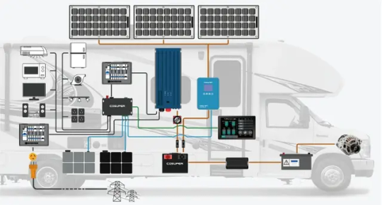
RV Solar System: How to Go Off-Grid with Panels and Batteries
The RV solar power supply system is the core equipment for achieving "off-grid freedom". Solar energy is converted into electrical energy through solar panels, and then it is used to power on-board electrical appliances (such as refrigerators, air conditioners, lighting, etc.) after solar batteries and regulation. It is particularly suitable for long-distance camping, outdoor adventures and other scenes with unstable power environment. Although the system structure looks simple on the surface, it is necessary to take into account power generation efficiency, solar battery capacity and space adaptability in design and actual application.
This article will analyze the key contents of the RV solar power supply system in detail from three aspects: system core components, design points, and use and maintenance.
1. System Core Components
The RV solar power supply system is usually composed of four modules: power generation, energy storage, control, and power consumption. The performance of each component directly determines the power supply stability and reliability of the entire system:
1.1 Solar Panels
1.1.1 Function:
-Converts light energy into direct current
1.1.2 Common types and suitable scene selection
- Monocrystalline silicon panels: high efficiency (18%-23%), suitable for rooftop paving;
- Flexible panels: bendable, suitable for curved roofs, slightly lower efficiency (15%-18%)
1.2 Solar Batteries
1.2.1 Function:
-Store electricity for use on cloudy days or at night
1.2.2 Common types and suitable scene selection
- Lithium battery (lithium iron phosphate): lightweight, long cycle life (3000 times +), suitable for frequent charging and discharging;
- Lead-acid battery (colloid/maintenance-free): low cost, slightly better low temperature performance, but heavy and short life (300-500 times)
-Charge and discharge rate (RV recommended 1C and above)
Brovolt's 12V/24V lithium iron phosphate (LiFePO₄) battery has high energy density, long cycle life, excellent safety and excellent temperature control adaptability, making it an ideal on-board energy storage solution.
-High energy density, light and space-saving: suitable for limited RV storage space, easy to install under seats, trunks and other locations.
-Ultra-long life ≥ 3000 cycles: compared with lead-acid batteries, the service life is increased by 4~6 times, especially suitable for solar energy systems with frequent charging and discharging.
-Safe and stable: using lithium iron phosphate cells, good thermal stability, support large current charging and discharging, with BMS (battery management system) multiple protection.
-Optional 12V/24V multiple voltage platforms: meet different system design requirements
-Support parallel expansion: flexibly build 1~5kWh energy storage units to meet different travel lengths and electrical loads.
1.3 Solar Controller
1.3.1 Function
-Regulate the charging process to protect the battery from overcharge/overdischarge
1.3.2 Common types and suitable scene selection
- PWM controller: simple structure, low cost, suitable for low-power systems (≤300W);
- MPPT controller: tracks the maximum power of the solar panels, high efficiency (90%-97%), suitable for high-power systems (≥500W)
-Rated current (≥1.2 times the total current of solar panels); whether with temperature compensation / USB output
1.4 Inverters
1.4.1 Function
-Convert direct current (12V/24V) to alternating current (220V)
1.4.2 Common types and suitable scene selection
- Modified wave inverter: drives low-power resistive appliances (light bulbs, mobile phone chargers);
- Pure sine wave inverter: adapts to inductive loads such as refrigerators and air conditioners to avoid equipment damage
-Continuous power (≥ total power of all electrical appliances); peak power (to cope with instantaneous power when the motor starts)
2. Analysis of the "full-link" design from power generation to power consumption: customized on demand, balancing "power generation-energy storage-space" .
The roof area of RVs is limited (usually 3-6 square meters). When designing the system, it is necessary to reasonably configure it according to the actual power demand and the body structure to avoid "power redundancy wastes space" or "insufficient power supply affects the experience".
2.1. Clarify the daily electricity demand and calculate the "electricity bill" first
Statistic the power and usage time of common electrical appliances:
-12V car refrigerator (50W, 8 hours of work per day) = 0.4kWh
-220V laptop (60W, 4 hours of use) = 0.24kWh
-Add LED lights, mobile phones, camera charging, etc., the total daily energy consumption is about:
-Light use: 1-2kWh/day
-Heavy use (including air conditioners, induction cookers, etc.): 3-5kWh/day
2. 2 Calculate the power of solar panels to ensure power generation needs
Considering the power generation efficiency decreases on cloudy days (only 30%-50% of sunny days), it is recommended that the total power of solar panels be configured according to the following formula:
Total power = average daily energy consumption × 1.5 ÷ effective sunshine duration (hours)
Example:
-Average daily power consumption 3kWh, effective sunshine 4 hours
-Required PV module power = 3��1.5÷4 ≈ 1125W
-Optional configuration: 300W×4
2.3 Configure battery storage system to ensure power supply at night and on cloudy days
The battery capacity needs to meet the power supply requirements for 2-3 consecutive days:
For example, if the daily power consumption is 3kWh, use 12V system:
Battery capacity = 3×2 ÷12V = 500Ah
Or choose 24V system: 250Ah (the higher the voltage, the smaller the line loss)
2.4 Optimize the installation position based on vehicle space
Lithium batteries are small and can be flexibly placed under seats, in the trunk, etc.
Lead-acid batteries are heavy and are recommended to be installed on the chassis or at the center of gravity to avoid the center of gravity shifting during vehicle driving.
It is recommended that photovoltaic panels be laid flat in an unobstructed area (such as between air conditioners and skylights), with an inclination angle close to the latitude (such as 30° at 30° north latitude) to improve the power generation efficiency at noon.
If the roof area is insufficient, you can use:
Retractable photovoltaic panels (unfolded when parking, folded when driving);
Foldable portable panels (used for temporary parking and charging).
3. Usage and Maintenance Guide: Key Details to Improve System Efficiency and Extend Life
RV solar generator systems are exposed to complex outdoor environments such as vibration, high temperature difference, and dust for a long time, so regular maintenance is required:
3. Usage and Maintenance Guide: Key Details to Improve System Efficiency and Extend Life
RV solar generator systems are exposed to complex outdoor environments such as vibration, high temperature difference, and dust for a long time, so regular maintenance is required:
3.1 Solar panel maintenance: maintain efficient power generation
-Clean dust and bird droppings on the panel surface every week (especially after rainy days)
-Clean up snow and fallen leaves in time
-Check the wiring interface to avoid loosening or oxidation caused by vibration
-The wiring terminal is sealed with waterproof glue, and the MC4 plug is protected with waterproof paste
A 10% blocked area may cause the power generation efficiency to drop by up to 50%.
3.2. Battery storage maintenance: extend battery life (combined with climate conditions)
Temperature management: lithium-ion batteries are afraid of high temperatures (>40℃), and low temperatures will affect the capacity of lead-acid batteries; Recommendations:
-Avoid heat sources such as engines and exhaust ports
-Use battery insulation devices or choose low-temperature resistant batteries in winter
Charge and discharge management:
-The remaining power of lithium-ion batteries should be ≥10%, and that of lead-acid batteries should be ≥30%
-When parked for a long time, the power should be maintained at 50%-60%, and recharged every 2 weeks
3.3 Check the operation of the solar controller and inverter
-Check the display interface of the controller to confirm whether the charging mode is "equalized charge" or "floating charge"
-Clean the dust from the heat dissipation holes of the controller to avoid overheating
-If the controller has an "overcharge protection" alarm, check whether the total photovoltaic power exceeds its rated value
-When using the inverter, avoid long-term full-load operation; turn off the inverter in time after turning off the electrical appliances to prevent no-load power consumption.
3.4 Advanced optimization plan: realize stable, safe and efficient off-grid life
Multi-source complementary power supply system:
-Add AC charging module and driving generator interface
-When solar power is insufficient, the power can be supplemented by vehicle operation or external power supply to build a "solar-vehicle-electricity" three-element complementary system
Optimize power usage habits:
-Prioritize the use of 12V native DC appliances, such as LED lights and car refrigerators
Reduce conversion losses during DC to AC conversion
-High-power equipment (such as microwave ovens and induction cookers) is recommended to be used during the peak power generation period at noon to avoid over-discharging the battery
Conclusion: Let "sunshine energy" truly serve travel life
The core concept of the RV solar power supply system is "configuration on demand, meticulous maintenance". A well-designed system can meet more than 80% of daily electricity needs, greatly reducing dependence on camp power supply, and achieving true freedom of travel.
Whether it is a short weekend trip or a long-distance cross-border trip, as long as the use strategy is adjusted according to the environment and the status of system components is checked regularly, "sunshine" can become a reliable and stable mobile energy source, making RV life more secure and free.
0 notes
Text
How to Design 5kW Solar Generator Systems?
In many regions of Africa or areas with unstable power supply, off-grid solar generator systems provide users with stable and reliable clean energy solutions. This system consists of solar panels, solar battereis,solar inverters and distribution boxes. It generates electricity using solar energy during the day and charges the solar battery at the same time. At night or during power outages, it is powered by the solar batteries and does not rely on the national power grid. The system features independent power supply, quiet operation, zero fuel consumption and zero emissions, making it particularly suitable for use in scenarios such as villages, farms, schools, clinics and water pumps. It is easy to install and has low maintenance costs. Even in areas lacking professional electricians, it can be quickly deployed, helping users achieve energy self-sufficiency and improve the quality of life and production efficiency.
The following is the detailed design plan of the 5kW off-grid solar generator system made by Brovolt Tech Company Limited for the customer, covering the selection of solar panels, solar battery selection, system configuration, and installation layout. It is suitable for families, remote areas, or emergency scenarios

Refrigerator 200W : 24×200W=4.8kWh/ day.
Air conditioner 1500W 3 ×1.5kW=4.5kWh/day
Lighting + TV: 3kWh/day
Total demand: 12.3kWh/day
The customer requests that electricity be provided for three days on rainy days. It needs to store 45kWh (considering the depth of discharge, with lithium batteries calculated at 95%, a total capacity of 48kWh is required).
The peak power is approximately 2000W, calculated based on the power of the customer's electrical appliances. Most of the customer's electrical appliances are inductive loads.The inductive load will have 2-3 times the impact current at the start instant.
2.. Selection and Configuration of PV Modules
2.1 Solar panels
Type: Monocrystalline silicon (efficiency ≥24%, good low-light performance).
Total power: 5kW (actually over-configured to 6kW, to cope with rainy days and losses).
Quantity: 12 pieces ×500W per piece (each piece is approximately 2.2m×1.1m in size).
Maximum power (Pmax/W) 600W
Open-circuit voltage (Voc/V) 52.81V
Short circuit current (Isc/A) 44.66A
Peak power voltage (Vmp/V) 13.44V
Peak power current (Imp/A) 23.2%
Actual power generation calculation: 6000W4h0.85=20.4kWh
Tilt Angle design: Adjust according to local latitude (for example, in areas at 30° south latitude, the tilt Angle is 30° to 35°).
Layout method
Flat roof: Saves space and needs to be fixed to prevent wind.
Ground support: Adjustable Angle, enhancing power generation efficiency.
2.2 Off-grid inverter
Nominal Power: 5kW (Select a power frequency inverter, resistant to shock loads such as motor start-up).
-Peak power is 10kW, which can meet the power demand at the moment of inductive load startup.
Battery type: 48V lithium ion solar batteries or llead acid batteries
-Output: 230VAC ± 5% @ 50/60Hz,pure sin wave
-MPPT operating voltage range:120VDC ~ 450VDC
-Max input voltage:500VDC
-THDi<3%
-Maximum photovoltaic input power is 6000W
Supports bypass charging from Gird or generator.
Switching time <20ms when outage
Solar batteries
Here we recommend Brovolt 51.2V314Ah solar inverter batteries.16kWh×3 =48kWh, with a cost of approximately 2400 USD.
-Smart Management: Built-in BMS that provides multi-level protection, including overcharge, over-discharge, and overheating, enhancing system reliability.
-Parallel Expansion: Supports parallel usage, supporting 16 units in parallel for easy expansion. Allowing capacity to scale up to 225 kWh
-Compatibility: Compatible with most inverters。
-Type: Lithium iron phosphate battery, LiFePO4 batteries, LFP batteries, lithium ion batteries.
-Features: The cycle life can reach up to 6,000 times, far exceeding that of lead-acid batteries. The warranty exceeds five years
-It is suitable for long-term and high-frequency usage scenarios, meeting the start-up requirements of high-power equipment such as air conditioners and water pumps. It has a low self-discharge rate and good long-term storage performance

4. Solar bracket and auxiliary materials
-solar brackets: Made of hot-dip galvanized steel, (adjustable Angle).
- Cables: PV dedicated DC lines (4mm² to 6mm²), copper core cables for AC lines
- Distribution box: includes DC circuit breakers, SPD, and FUSE,RCD,MCB.
5. Installation of photovoltaic arrays
5.1 Roof installation:
- Flat roof: Use inclined supports, leaving 0.5 meters of heat dissipation channels at intervals.
- Sloping roof: Directly fixed, waterproof treatment is required.
5.2 Ground installation:
- Concrete foundation + adjustable supports, avoiding shadow obstructions.
The height from the ground should be no less than 0.5 meters (to prevent water accumulation).
6. Layout of equipment rooms
- Solar Batteries and inverter: Install in a well-ventilated and dry independent room (avoid high temperature/humidity).
- Cable routing: DC lines and AC lines are laid separately to reduce interference.
- Lightning protection grounding:
The grounding resistance of the solar brackets is ≤4Ω.
The distribution box is equipped with a secondary lightning protection module.
7. Operation and Maintenance and Fault Handling
7.1. Daily maintenance
Clean the photovoltaic panels monthly (increase the frequency in areas with sand and dust).
Check if the terminal blocks are loose.
7.2. Battery maintenance
- Lithium battery: Monitor the charging and discharging status through BMS.
7.3. Common Faults
- Inverter overload: Reduce the simultaneous use of high-power appliances.
- Decline in photovoltaic panel efficiency: Check for obstructions or aging.
8. Plan Summary
Through this solution, the 5kW off-grid system can achieve stable power supply, with an average daily power generation covering household demands, and it also features scalability and high reliability. In the actual design, the inclination Angle and capacity need to be further optimized in combination with the local lighting data (the NASA SSE database can be
0 notes
Text
How to Design Solar and On-off-grid Energy Storage Systems?
Solar on- off-grid energy storage systems are widely used in factories, commercial facilities and other places with large peak-valley price differences or frequent power outages. The system is composed of photovoltaic arrays made up of solar panels, combiner boxes, hybrid inverters, solar batteries, loads, power grids, etc. PV array converts solar energy into electrical energy under the condition of sunlight, supplies power to the load through a hybrid inverter, and charges the battery pack at the same time. The excess electricity can also be fed into the power grid. When there is no light, the load is powered by the power grid. When the power grid is out of power, the battery supplies power to the load through the hybrid inverter.Visit more
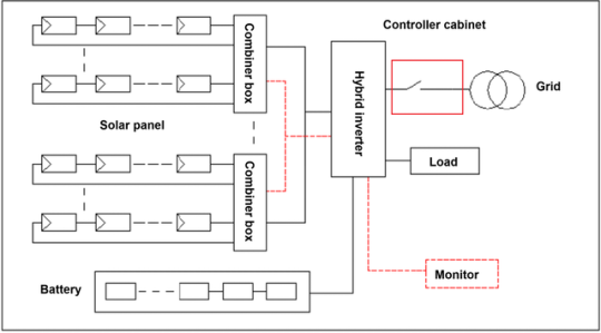
I. Main Components of the System
1.1 Solar panels
It is the main component of the solar power supply system and also the most valuable part in it. Its function is to convert the radiant energy of the sun into direct current electrical energy.
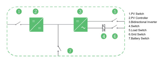
1.2 Hybrid inverter
The main functions are divided into two parts: the MPPT solar controller and the bidirectional DC/AC converter. Their role is to regulate and control the electrical energy generated by the solar panels charge the battery, and provide overcharge protection and overdischarge protection for the battery. At the same time, the direct current from the components and the battery is converted into alternating current for use by AC loads. When appropriate, the power grid can also charge the battery.
1.3 Solar batteries: Its main task is to store energy to ensure the power supply for the load when the power grid is cut off.
2. Main Components
2.1 Solar panels
Solar panels are solar power generation devices that directly convert solar energy into direct current electrical energy. According to the different requirements of users for power and voltage, solar panels can be made for individual use, or several solar panels can be connected in series (to meet voltage requirements) and parallel (to meet current requirements) to form a power supply array to provide greater electrical power. The power generation of solar cells increases proportionally with the increase of sunlight intensity. It slightly decreases as the surface temperature of the component rises. As the temperature changes, the current, voltage and power of the battery components will also change. When designing the components in series, the negative temperature coefficient of the voltage must be taken into consideration.

2.2 Hybrid Inverters
Three-phase solar hybrid inverter integrated machine, adopting the new generation of all-digital control technology, pure sine wave output; The solar controller and inverter are integrated into one, making it convenient to use. It is suitable for areas with power shortages and unstable power grids, providing an economical power supply solution. The product has the following advantages:
(1) Control hybrid inverter: Integrated solar controller and inverter, simple connection, convenient to use;
(2) High efficiency, with an efficiency of over 95%, maximizing the utilization of solar energy.
(3) High reliability: The inverter adopts power frequency design, has strong overload capacity, and is suitable for impact loads such as air conditioners.
(4) Comprehensive protection functions: Battery overcharge and overdischarge protection and advanced battery management functions extend the battery life. Overload protection, short-circuit protection and other functions ensure the safe and reliable operation of equipment and loads.
(5) The LCD liquid crystal screen provides intuitive display: monitoring of multiple working operation status parameters such as photovoltaic input voltage/current, AC output voltage/current, and battery capacity.
(6) The energy storage system is compatible with both lead-acid batteries and lithium batteries, providing users with multiple options.
(7) Various charging methods such as PV charging, mains (generator) charging, and hybrid charging, as well as multiple power supply methods including battery power supply and mains power supply.
(8) It supports multiple inverters running in parallel, making power expansion convenient.
2.3 Solar Batteries
Solar batteries and related devices are an indispensable part of solar generation systems. They are mainly used to store electricity generated by solar energy and provide continuous power to loads at night, when there is insufficient sunlight or in emergencies. Common solar battery technologies include lead-acid batteries, alkaline batteries, supercapacitors and lithium batteries, each with different application ranges. Currently, the most widely used are lithium-ion batteries, especially lithium iron phosphate batteries (LFP), which perform well in solar systems due to their high safety, long life and excellent cycle performance. Since the advent of lithium battery technology in the 1980s, a variety of types have been developed, including ternary lithium, lithium iron phosphate, lithium titanate, etc.In this solution, we choose Brovolt 215 kWh lithium-ion battery cabinet.
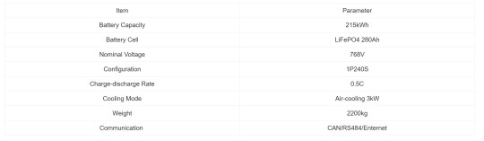
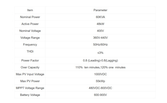
3.Solution design
Solar : monocrystalline 550W, quantity 100 pieces, 20 series and 1 parallel, total power 55kW.
Hybrid inverter: power 48KW
Lithium-ion battery cabinet: 215kWh.
0 notes
Text
Integrated Solar, Storage, and EV Charging Solution for Parking Lots
This article is selected from the technical solution of the parking lot photovoltaic storage and charging integrated project tailored by Brovolt for customers. The solution comprehensively considers the efficient coordinated operation of solar photovoltaic power generation, energy storage system and electric vehicle charging piles, covering the charging pile configuration plan, energy management system (EMS) strategy, economic benefit analysis and project equipment list. The solution aims to maximize the utilization of green energy, reduce peaks and fill valleys, and improve operational efficiency. It is suitable for urban smart transportation and new energy infrastructure construction.
This project plans to install 15 charging piles, featuring a 120kW dual-gun DC integrated machine design, with a total of 30 parking Spaces, which can meet the electricity demand.The demand for high-power and fast charging of automobiles.
Visit more: Integrated Solar, Storage, and EV Charging Solution for Parking Lots

3.1 Site Planning Scheme
The central driving lane of the planned site reserves sufficient space to ensure the normal turnover of vehicles. A total of 30 standard parking Spaces are arranged, with two vehicles each
One charging pile is designed to be installed in the green belt behind the parking space. The battery compartment and equipment compartment are placed in front of the transformer
4. Energy Management System (EMS)
4.1 Introduction to the Energy Management System (EMS
The energy management system (EMS) is integrated into a monitoring cabinet and connected to data such as energy storage PCS, BMS and electricity meters.The internal configuration operation strategy monitors and controls the entire energy storage system, and can communicate with the remote information management system for acceptance dispatch. It has the following characteristics:
1.It has a rich built-in device protocol, dynamically loads devices, and can be connected to various energy storage and microgrid devices.
2.The data mutation upload and master call methods respond quickly and save bandwidth.
3.It is equipped with a built-in flexible operation strategy to support peak shaving and valley filling in the energy storage system.
4.The built-in reports are rich and diverse, and it supports report customization. The data analysis is detailed and in-depth.
5.Alarms, faults and events are pushed in real time or at regular intervals, and all kinds of data records are detailed and accurate.
6.The industrial-grade operation platform ensures a stable, secure and reliable system.
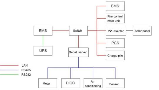
The energy storage PCS and solar batteries are connected to the switch via network cables and then connected to the EMS. PV system and the charging piles are connected through network cables.Change the machine and then connect it to EMS. Electricity meters, air conditioners, DIDO and other environmental monitoring devices are connected to EMS via RS485. Local customers are accessible.Access and operate EMS through PC access switch.
4.3 Functions of the Energy Management System (EMS)
EMS provides products that meet the monitoring requirements at the plant and station levels in different application scenarios such as storage and charging, and photovoltaic storage and charging. Its main functions include:Home page (Primary electrical diagram), Equipment Management, Alarm Management, Data Analysis, System Settings (User Management, Operation Strategy).
V. Overall Revenue Situation
5.1 Total Project Cost
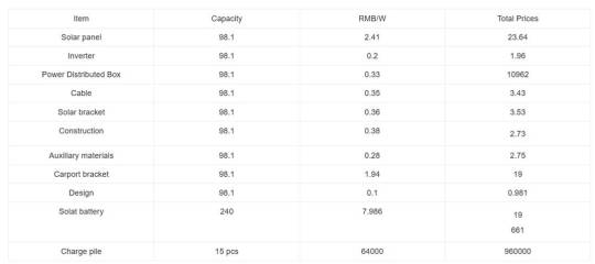
Based on the above information, the cost of photovoltaic modules is 236,421 yuan, the cost of carports is 190,314 yuan, and the cost of solar battery is 1,916,640 yuan, and the cost of the charging pile is 960,000 yuan, with a total cost of 3,303,375 yuan.
5.2 Annual maintenance content, costs and insurance costs
The annual maintenance of PV stations is relatively simple, mainly including the following points:
1. Operation status and power generation monitoring. The inverter can display the voltage of the string, real-time power generation, historical power generation statistics, fault alarm and other information, which can be monitored through the mobile phone app.
2. Cleaning of solar panel and line maintenance. Cleaning of solar panels is mainly to remove dust and bird droppings and increase power generation. Rainwater can also play a cleaning role. If there are no special requirements, it is generally cleaned once a quarter or half a year. Line inspection and maintenance can be included in the company’s overall regular line maintenance plan.
3. Check the tightness of the clamping bolts every 1–2 years, and tighten the loose bolts.
4. Replacement of damaged photovoltaic modules can be solved by contacting the equipment manufacturer or general contractor according to the contract and warranty agreement. The annual maintenance cost can be calculated according to the owner’s arrangement, mainly labor costs. Insurance is mainly to reduce losses caused by natural disasters and accidents. The general enterprise rate is 3%, and more favorable rates may be obtained according to the credit status of the enterprise.
5.3 Overall project revenue
Combined with electricity prices, the annual revenue from photovoltaic power generation for this project is as follows:
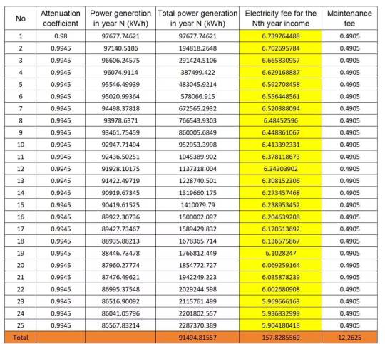
Within the 25-year life cycle of the photovoltaic equipment, the total operating income of the project is 15.78285569 million yuan. Based on the photovoltaic installation price of 6.35/W, the initial investment of the project is 6.22935 million yuan. Excluding the annual maintenance cost of photovoltaic equipment of 0.4905 million yuan. The overall static cost can be recovered in 10.45 years; the dynamic cost can be recovered in 19.90 years, and the after-tax financial internal rate of return is 6.66%. The overall project income is good. From the perspective of the overall project income, the income period is short and the financial internal rate of return is considerable; it relieves the pressure of electricity consumption and increases the implicit income.
0 notes
Text
120kW 240kWh Energy Storage for Solar-Powered EV Lots
This article is extracted from the technical plan of the parking lot photovoltaic storage and charging integrated project.
The project site is located in Ganzhou City, Jiangxi Province, which belongs to the South Asian tropical monsoon climate. The annual average temperature is 20.6℃, the annual average daily solar radiation is 3.48kWh/㎡, and the annual solar radiation is 1270.7kWh/㎡. The solar radiation is very rich, which is suitable for laying photovoltaic systems. When there is sufficient sunlight during the day, if the electricity generated by the photovoltaic system cannot be consumed in time, the energy storage system can store the electricity in time and supply power to the charging piles at night.
Please click this link to learn more
This project includes three parts: photovoltaic, energy storage and charging piles, and the project installation point is Ganzhou City. The technical plan was made by Brovolt based on customer needs and field surveys. This article explains the selection ideas and technical parameters of the energy storage system in the photovoltaic storage and charging plan.
1. System solution
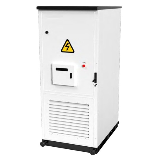
According to the overall project plan configuration, the energy storage system configuration specification is 100kW/240kWh, and it is installed in the form of an outdoor cabinet. The system mainly includes: lithium iron phosphate battery (Pack), battery management system (BMS), high-voltage control box (PDU), air conditioning, distribution box, outdoor cabinet, and PCS.
2. System Composition
2.1 Energy storage Battery System
The energy storage battery system adopts 314Ah/3.2V lithium iron phosphate cells, which consist of one battery cluster. 1P24S forms a 24.115kWh battery box. Ten battery boxes are connected in series to form a 241kWh battery cluster, with a voltage range of 672 to 864V. This system has two battery clusters with a total capacity of 241kWh. Multiple sets of energy storage battery systems can be used in parallel.
3) High-voltage control box:
The high-voltage control box (PDU) is composed of fuses, circuit breakers, contactors, shunt devices, BMS main control units, etc. The main functions of each component are as follows:
Fuse (FU) : It serves to protect against overload or short circuit in the circuit.
Circuit Breaker (QF) : The main output switch of the battery system, which cuts off the circuit when abnormal operating conditions occur in the system.
Shunt (FL) : For BMS current detection and information collection;
Contactor (KM) : Controls the charging and discharging circuits;
BMS master control: As the control center, it is responsible for the monitoring of the entire system's operation process, data processing, implementation of control strategies, and communication control
2 Battery Management System (BMS)
The battery management system adopts a three-level architecture and is equipped with a total of 10 24-string slave controllers (BSU) and 1 master controller (BMU).One BMS heap controller (BDU), supporting active equalization.
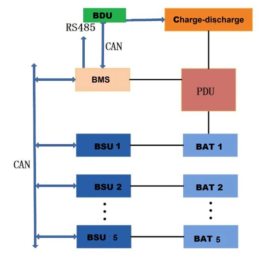
1) BDU module parameters and main functions
The BDU is at the top of the three-tier architecture of the battery management system and is mainly responsible for collecting real-time data of the BMU.It integrates real-time computing, performance analysis, alarm handling, protection handling and record storage. In addition, BDU is also responsible for storage.The power conversation system (PCS) and the upper-level energy management system (EMS) communicate to achieve interconnection
BDU main functions:
a) Local operation status display function: Through the UI interface of BDU, various operation statuses of the battery system can be displayed locally, such as system status, individual battery voltage, temperature, SOC, SOH, alarm and protection information.
b) Communication protocol conversion function: Supports Modbus-TCP protocol conversion and conducts information interaction with the energy management system through the Modbus-TCP protocol.
c) It has the function of communicating with PCS: It supports information interaction with PCS through the CAN interface to achieve the charging and discharging control of the battery stack.
d) Operation parameter setting function: The various parameters of the battery management system operation can be modified, configured and saved through BDU.
(2) BMU module parameters and main functions
The BMU is a controller module integrating functions such as cluster total voltage/total current collection, charge and discharge management, insulation detection, and BSU management.
BMU Main features:
a) The current acquisition sensor is compatible with multiple models such as shunt sensors, LEM Hall sensors, open-loop Hall sensors, and closed-loop Hall sensors.
b) The battery management system should be capable of detecting data related to battery heat and electricity, at least including parameters such as insulation resistance and internal and ambient temperatures.
c) The battery management system should be capable of estimating the state of charge (SOC) and battery health (SOH) of the battery, and conducting automatic calibration. It is capable of calculating, real-time local display and reporting the number of cycles (calculation formula: cumulative charge/(nominal capacity *90%), DOD, SOC, SOH). The battery can automatically perform SOC calibration and battery balancing during operation.
d) The battery management system plans the charging and discharging control of the battery based on its state of charge. If the battery voltage exceeds the standard or there is an overcurrent, the system must immediately stop the battery operation.
e) Battery system operation alarm function: When the battery system operates in states such as overvoltage, undervoltage, overcurrent, high temperature, low temperature, abnormal communication, or abnormal battery management system, it should be able to display and report alarm information.
f) The battery management system should have the function of information interaction with the converter, local monitoring device and energy management control system, and should provide RS485, CAN and Ethernet communication interfaces.
3) BSU module parameters and main functions
The BSU provides real-time collection of individual cell voltage and temperature, and also features thermal management and bidirectional active balancing capabilities. It is interconnected with the main control module via the CAN bus.
The main functions of BSU:
a) It supports parameter configuration function. Parameters can be configured based on the actual number of battery strings connected and the number of temperature sensors. It also allows for the configuration of heating/fan on/off temperatures.
b) Configurable active balancing or passive balancing is available. The battery management system should have a balancing management function, capable of balancing the inconsistent differences among battery packs and clusters.
c) The battery management system should be capable of detecting thermal and electrical data related to the battery, at least including parameters such as the voltage, current, insulation resistance, and internal and ambient temperatures of individual battery cells and battery packs.
d) The battery management system should be capable of diagnosing battery faults, providing disconnection protection, balancing fault detection, and handling corresponding faults based on specific fault contents. It should have, but not be limited to, the following protection functions: overcharge protection, overdischarge protection, short-circuit protection, overload protection, and temperature protection. The relevant fault information should have functions such as fault information upload and real-time alarm.
2.3 Distribution Box
The incoming line of the secondary power distribution system is single-phase three-wire, which can provide independent control switches and 220V single-phase AC power supply for AC power equipment such as outdoor cabinet air conditioners, switching power supplies, fire protection, and sockets, to ensure the stability of the system. The 220V power supply is provided externally.
2.4 Air Conditioning System
The system is equipped with an industrial air conditioning system to regulate the temperature inside the outdoor cabinet. When the battery temperature is detected to reach a certain limit value, an instruction is sent to the air conditioning system to control it to start operating, keeping the system temperature inside the box within an appropriate range. The system has four working modes.
Refrigeration
The parameters of the air conditioner can be set through the display screen or the background software: the set cooling temperature and the cooling deviation temperature. When the temperature inside the chassis is higher than (the set temperature for refrigeration + the deviation temperature for refrigeration), refrigeration begins. When the temperature inside the chassis is lower than the set temperature for cooling, the cooling will stop.
(2) Heating
The air conditioner can be set with parameters: heating set temperature and heating deviation temperature. When the temperature inside the chassis is lower than the set heating temperature, heating begins. When the temperature inside the chassis is higher than (the heating start temperature + the heating deviation temperature), the heating stops.
(3) Supply air
The air conditioner can achieve uniform temperature distribution inside the chassis through the air supply function, avoiding local overheating inside the box. When the temperature inside the unit is lower than the cooling start temperature, the air supply function will be automatically activated.
(4) Dehumidification
When the humidity inside the box is greater than the humidity at which the dehumidification is activated and the temperature inside the box is lower than the temperature at which the dehumidification is activated, the electric heating dehumidification is connected. Stop heating when the temperature inside the box rises to the dehumidification stop temperature or the humidity drops back to the dehumidification stop humidity.
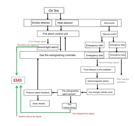
2.5 Fire Protection System
The fire protection system equipped in this energy storage battery system has two control modes: automatic and manual. When the alarm controller is in the automatic state and receives the first linkage signal, the sound and light alarm will sound an alarm, indicating the location where the fire occurs and reminding the staff to pay attention. When the second linkage trigger signal is received, the automatic fire extinguishing controller begins to enter the delay stage (adjustable from 0 to 30 seconds), and the delay is too long
Afterwards, the controller issues a fire extinguishing command, opens the solenoid valve, then opens the gas storage cylinder to carry out fire extinguishing operations in the fire area. At the same time, the alarm controller receives the feedback signal from the pressure signal device, and the spray indicator light on the control panel lights up. When the alarm controller is in manual mode, it only issues an alarm signal and does not output an action signal. After the on-duty personnel confirm the fire alarm, they can press the emergency start button on the alarm control panel or the emergency start-stop button at the entrance of the protected area to start the system and release the fire extinguishing agent.
0 notes
Text
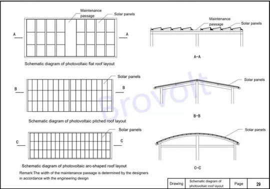
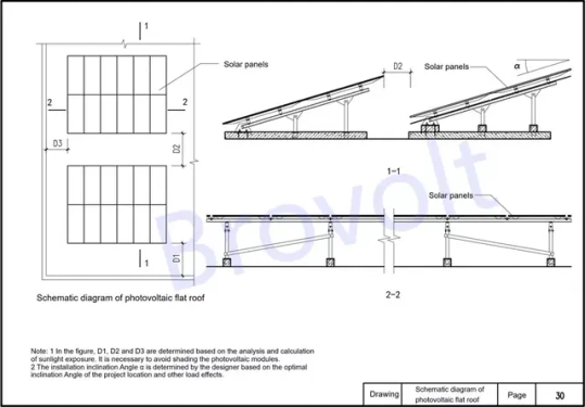
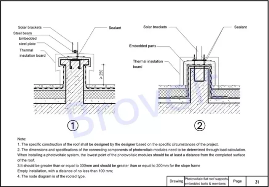
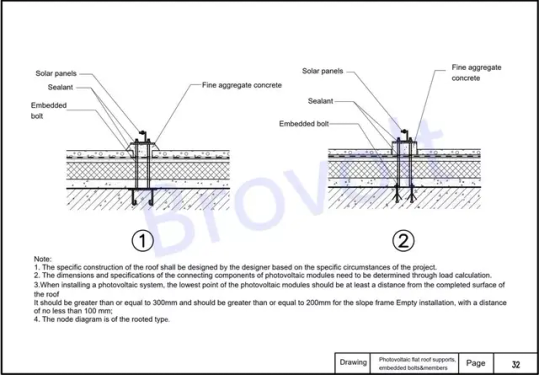
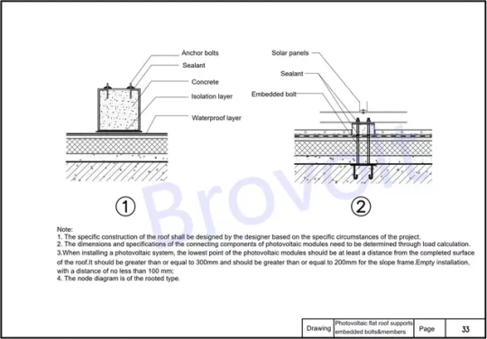
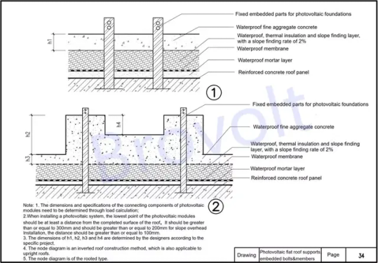
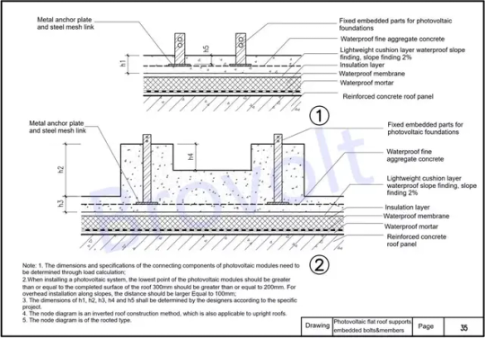
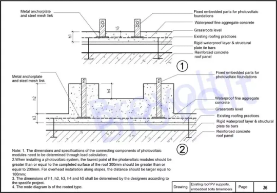
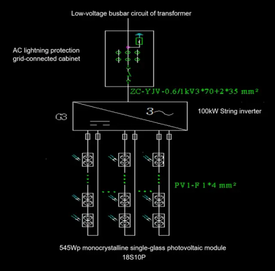
This atlas provides schematic diagrams for solar panel installation, including: PV Roof Layout Shows panel arrangement on sloped or color steel roofs, including spacing and tilt angles. PV Flat Roof Layout Illustrates panel layout on flat concrete roofs, with bracket placement, access paths, and tilt design. Embedded Bolt Installation Details the pre-embedding of foundation bolts for flat roof supports, covering positioning, depth, and waterproofing.
Please check link below to learn more
0 notes
Text
How to Build a 100kWp PV System and Energy Storage for Solar-Powered Parking Lots
In a smart parking lot energy solution that integrates photovoltaic power generation, energy storage, and EV charging,
the PV system serves as the primary source of clean and renewable electricity. This solution features a 100kWp solar power system designed to efficiently convert solar energy into usable electricity for EV chargers and battery storage. Strategically installed across the parking structure, the PV modules maximize rooftop or canopy space while reducing carbon emissions and operational costs. By generating power during daylight hours, the PV system minimizes grid dependency and enhances energy self-sufficiency. This section provides a detailed overview of the PV system design, component selection, installation methods, and its key role in enabling a sustainable and cost-effective parking lot energy solution.
I. Photovoltaic Solutions
Project Overview
1.1. Project Location
The project site is located in Ganzhou .Ganzhou is situated in the upper reaches of the Ganjiang River, in the south of Jiangxi Province, and has a typical subtropical monsoon climate. The geographical coordinates are between 24 °29 'and 27 °09' north latitude and 113 °54 'and 116 °38' east longitude. The annual average temperature is 20.6℃, the annual average daily solar irradiation is 3.48kWh/㎡, and the annual solar irradiation is 1270.7kWh/㎡. The solar irradiation is very abundant. Suitable for laying photovoltaic systems.
This project consists of three parts: photovoltaic, energy storage and charging piles. The installation site is located in Ganzhou. After on-site investigation, there are no tall buildings blocking the installation site around it, and the lighting conditions are good, which is suitable for installing photovoltaic. When there is sufficient sunlight during the day, if the electricity generated by the photovoltaic system cannot be consumed in time, the energy storage system can store the electricity promptly and supply power to the charging piles at night.
1.2. Project ScaFigure 1-1 Floor plan of the parking lotle
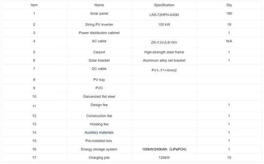
The project plans to build photovoltaic carports at parking Spaces. There will be a total of 30 parking Spaces. solar panels will be laid on the photovoltaic carports, and the solar panel is planned to use 545Wp solar panels.
The floor plan of the parking lot is shown in Figure 1-1. The parking lot has two rows of parking Spaces, with a total of 30 parking Spaces. Among them, there are 16 parking Spaces in the first row and 14 in the second row. Photovoltaic carports can be designed and customized according to the customer's requirements for the height, width and appearance of the carport. Figure 1-2 shows the design drawing of a certain type of photovoltaic carport for reference.
According to the site plan of the parking lot, solar panels are laid. No maintenance passages are reserved between the solar panels. The solar panels used are 545Wp solar panels, with each module measuring 2256*1133mm. A total of 180 solar panels can be laid, and the installed capacity is 98.1kW. The specific laying diagram is shown in Figure 1-3.
Click the link below to learn more.
0 notes
Text
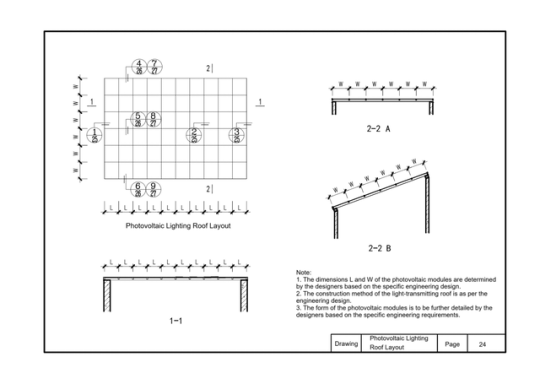
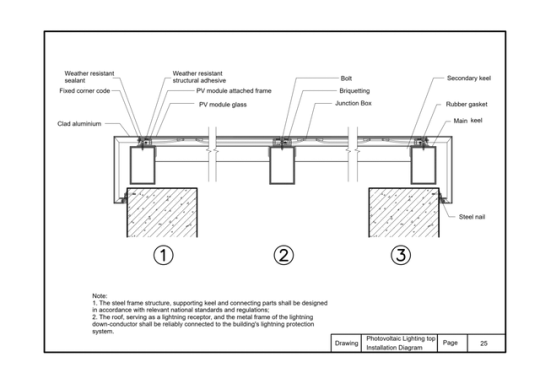
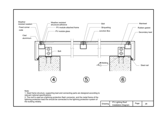
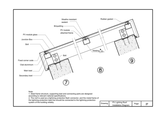
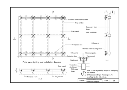
This atlas is derived from the guiding atlas for the design of building photovoltaic systems. It includes layout and installation diagrams for photovoltaic skylights, as well as installation diagrams for point-supported glass photovoltaic skylights. It briefly demonstrates how common components are installed, such as stainless steel connection claws, cable trays, secondary steel beams, photovoltaic modules, main steel beams, junction boxes, aluminum pressure plates, and point-supported accessories
0 notes
Text
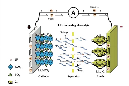
Lithium ion batteries are widely used in energy storage and electric vehicle applications due to their safety, long cycle life, and stable performance. In this article, we will explore what lithium ion batteries are, how they work, their history, materials, manufacturing process, advantages and disadvantages, comparisons with other batteries, tips for choosing the best manufacturers, and their market demand.
1. What is a lithium-ion battery?
Lithium-ion Battery (Li-ion) is a rechargeable battery technology that uses the movement of Lithium ions to achieve energy storage and release. Lithium-ion batteries have the characteristics of high energy density, low self-discharge rate, no memory effect, long cycle life, etc., and are the most mainstream battery types for consumer electronics, electric vehicles, and energy storage systems.
1.1 Structural composition:
1.1.1 Positive electrode: the source of storage and release of lithium ions, which determines the voltage and energy density of the battery. Typically made from lithium iron phosphate (LiFePO₄), ternary lithium (NCM/NCA), or lithium manganate (LiMn2O4).
1.1.2 Negative electrode: Used to store lithium ions and release lithium ions when discharged. The main material is graphite (C), silicon carbon composite or lithium titanate (LTO).
1.1.3 Electrolyte: Acting as a transport medium for lithium ions, usually a lithium salt (such as lithium hexafluorophosphate LiPF₆) dissolved in an organic solvent
1.1.4 Diaphragm: Porous membrane material that allows lithium ions to pass through but prevents electrons from directly short-circuiting. Commonly used polyolefin (PE, PP) diaphragms.
2.How do lithium-ion batteries work
A lithium-ion battery is a rechargeable electrochemical device based on the principle of the conversion of electrical and chemical energy by the insertion and de-insertion of lithium ions (Li +) between positive and negative electrodes.
2.1. Charge process (Li + from positive → negative)
When the battery is charged, an external power supply applies a voltage push:
Lithium ions and electrons are released from the cathode material:
LiCoO2 →Li1-XCoO₂ + xLi+ +Xe-
Lithium ions (Li +) travel through the diaphragm through an electrolyte and migrate to the negative electrode.
Electrons (e⁻) are synchronized to the negative electrode by an external circuit. The negative electrode (such as graphite) is embedded in the lithium ion, forming a LiC₆
xLi++xe-+C6→ LixC6
At this time, the electrical energy is "stored in the negative electrode" to complete the charge
2.2 Discharge process (Li + from negative → positive)
When the battery discharge (power supply) , the direction of electrochemical reaction is reversed:
2.2.1 Lithium atoms in the negative electrode release lithium ions and electrons
2.2.2 Lithium ions return to the positive electrode through the electrolyte
2.2.3 Electrons flow along the outer circuit to the positive terminal, producing a current output
2.2.4 The positive electrode is re-embedded in lithium ion to complete energy release
3. Development history of lithium-ion batteries
The development of lithium-ion batteries spans decades, covering multiple stages from theoretical proposals, technological breakthroughs to commercial applications and future technology exploration. The following is its key time nodes and stages of progressTheoretical foundation stage
3.1 1958: American physical chemist Gilbert N. Lewis first proposed the concept of "lithium battery".
Early 1970s: Dr. M.S. Whittingham develops the first lithium metal battery, using a TiS2 positive + lithium metal negative electrode, but it has serious safety problems (short circuit and explosive).
At this stage, although the energy density of lithium metal batteries is high, the safety hazards caused by lithium dendrites are difficult to overcome.
3.1. Lithium-ion battery principle established
1980: Professor John B. Goodenough invented lithium cobalt oxide (LiCoO₂) cathode material, voltage up to 4V, opening the era of high energy batteries.
1985: Dr. Akira Yoshino of Asahi Kasei, Japan, used graphite as a negative electrode material for the first time to develop a "metal-free lithium" lithium-ion battery prototype, greatly improving safety.
1986: Japan begins small-scale trial production of prototype lithium-ion batteries.
Yoshino, known as the "father of lithium-ion batteries," shared the 2019 Nobel Prize in Chemistry with Goodenough and Whittingham.
3.2. Commercialization takes off - SONY launches the world's first commercial lithium-ion battery
1991: Sony of Japan, in partnership with Asahi Kasei, launches the first commercial lithium-ion battery for cameras with high energy density, long life and superior safety.
In the late 1990s, laptops and mobile phones rapidly adopted lithium batteries, which led to an industry explosion.
This marks the official opening of the commercial era of lithium-ion batteries.
3.4. Material innovation and multiple applications
2001: Lithium iron phosphate (LiFePO₄) was developed as a new positive electrode material with improved safety for power and energy storage.
Since 2005: ternary material (NCM/NCA) has been put into industrialization to improve capacity and cycle performance.
2008: Tesla releases the first electric car Roadster, using lithium-ion cylinder battery (18650), electric vehicles into the mainstream vision.
A variety of new materials, cell structures (soft bag, cylinder, square) began to emerge.
3.3. Industry outbreak and energy storage revolution
After 2010: the surge in demand for electric vehicles and home energy storage systems led to the rapid development of the lithium battery market.
2013: BYD launches lithium iron phosphate electric bus.
2015: Tesla releases the Powerwall, a home energy storage system.
2018: Global lithium battery shipments exceeded 100GWh for the first time.
China, South Korea, Japan formed the "lithium battery three strong", CATL, BYD, LG, Samsung SDI and other rapid rise.
3.4. High energy, solid state, new system exploration
After 2020: New systems such as solid-state batteries, silicon-carbon anode, cobalt-free batteries, and sodium-ion batteries are continuously developed
2021: CATL releases sodium-ion battery samples.
2022: BYD launches "blade battery", using LFP to improve safety and space utilization.
2023: Global lithium ion battery shipments exceed 700GWh, and large-scale deployment of energy storage systems accelerates.
Since 2024, large-capacity energy storage power stations and household light storage systems have become the main market.
4. Detailed explanation of the main materials of lithium-ion batteries
4.1 Cathode material:
4.1.1 Lithium cobaltate LiCoO₂ : High energy density, often used in mobile phones and other devices
Ternary material NCM/NCA: the mainstream choice for electric vehicles, taking into account energy density and cost
Lithium Iron phosphate LiFePO₄ : Long life, high safety. Suitable for energy storage and household systems
Lithium manganate LiMn₂O₄ : Low cost, but relatively poor life and stability
4.1.2 Anode Material (Anode) :
Graphite: mainstream material, mature and stable
Silicon-carbon (Si-C) composites: Higher energy density, but large volume expansion, need to be controlled
Lithium titanate (LTO) : Extremely long cycle life, suitable for high rate applications
4.1.3 Electrolyte:
Composed of lithium salts (such as LiPF₆) and organic solvents, it conducts lithium ions
Solid-state electrolytes have been developed in recent years to improve safety
4.1.4 Separator:
Most of them are PP/PE microporous films with thermal closing function to prevent short circuit
4.2 Lithium iron phosphate battery(LiFePO4) outlook
Lithium iron phosphate battery (LFP) with its high safety, long cycle life and low cost, has become the absolute mainstream technology in the field of energy storage.
4.2.1 Main application scenarios in the energy storage field
Grid side energy storage (generation end + transmission and distribution end).
Peak and frequency modulation: LFP battery response speed up to millisecond, can replace traditional gas turbines, reduce grid fluctuation costs.
Smooth output of renewable energy: supporting photovoltaic/wind power projects to solve intermittency problems (such as 600MWh LFP energy storage power station in Qinghai Province, China).
Black start: provides support for the rapid restoration of power supply after grid failure (such as 182.5MW LFP energy storage system in California, USA).
User side energy storage (Industrial & Commercial + Household)
Peak-valley arbitrage: Industrial and commercial users take advantage of the price difference (such as China's peak-valley price difference exceeding 0.1USD /kWh), and the investment payback period is reduced to 5-7 years.
Standby power supply: Data centers, hospitals and other sensitive scenarios, LFP cycle life of more than 6000 times, reduce the replacement frequency.
Household light storage systems: LFP penetration in the European household storage market increases from 20% in 2020 to 60% in 2023 (Tesla Powerwall 3 fully switches LFP).
4.3 New Application Scenarios
4.3.1 Electric vehicle charging station energy storage: buffer the grid load and support the high-voltage demand of fast charging pile (such as the "optical storage and charging" integrated station cooperated by CATL and Star Charging).
4.3.2 Microgrid and off-grid power supply: Energy independence in remote areas/islands (such as the 50MWh LFP off-grid energy storage project in Tanzania, Africa).
4.4. Core advantages of LFP leading energy storage market
4.4.1 Economical rolling
Kilowatt-hour cost (LCOS) : LFP energy storage system LCOS has been reduced to 0.02-0.04 USD/time, lower than ternary batteries (0.0.045-0.0.06 USD/time) and lead-acid batteries (0.085 USD/time).
Cycle life: 6000 cycles (80% capacity retention rate) vs 3000 cycles for ternary batteries, 500 cycles for lead-acid batteries.
4.4.2 Outstanding Security Performance
Thermal stability: LFP thermal runaway temperature > 500℃, much higher than ternary battery (200℃), through acupuncture, overcharge and other safety tests.
Cobalt-free nickel controversy: circumventing the resource monopoly of cobalt-nickel in ternary materials (Congo cobalt mines account for 70%) and moral hazard (child labor).
Meet the requirements of the energy storage scenario
Low self-discharge rate: monthly self-discharge < 2%, suitable for long-term idle backup power supply scenarios.
Wide temperature range: Stable operation from -30 ° C to 60 ° C through electrolyte formulation optimization (e.g. adding LiFSI).
4.5. Global market pattern and competitive dynamics
Market size and growth
China: New energy storage installed capacity of 21.5GW in 2023, LFP accounted for more than 95%b), 2025 planning target of 60GW.
Europe and the United States: The US IRA bill promotes the increase of energy storage installed capacity by 200% in 2023, and the proportion of LFP rises from 30% to 65%; The LFP penetration rate of the European household storage market exceeds 70%.
Emerging markets: energy storage demand in Southeast Asia and Africa is increasing by 50% annually, and Chinese manufacturers dominate exports.
5. Production process of lithium-ion batteries
Lithium battery manufacturing process is strict, mainly including the following five steps:
1. Electrode preparation
Mix: Active material + binder + conductive agent
Coating: The paste is evenly applied to the aluminum/copper foil
Drying: Remove solvent
Compaction: Increase the density and consistency of the pole plate by rolling
2. Battery assembly
Pole cutting and lamination/winding: The core structure is formed according to the cell type
Diaphragm insertion: prevents short circuit
Injection electrolyte
Package sealing: Use aluminum shell, soft package or cylindrical package form
3. Formation and separation
Formation: First charge and discharge to form a stable SEI film
Capacitance: Test the capacity, voltage, internal resistance of each cell, and grade sorting
4. Module/battery pack assembly
Parallel/series configuration: Modules are assembled according to the system voltage and current requirements
Integrated BMS system: Monitor temperature, voltage and current for safe operation
5. Final inspection and delivery
Quality test: including capacity, life, drop, temperature cycle, etc
6.Advantages and disadvantages of lithium-ion batteries
Advantages:
1 High energy density: light size, strong power
2 Long life: cycle life can reach more than 2000~6000 times
3. Low self-discharge rate: long-term storage is not easy to lose power
4. No memory effect: It can be used on demand
5. Diversified packaging: suitable for different equipment requirements (soft package, cylinder, square)
Cons:
1. High cost: The price of high-quality lithium raw materials fluctuates greatly
2. Temperature sensitive: Performance declines under high temperature or extremely cold conditions
3. Risk of thermal runaway: Improper design /BMS may cause overheating or fire
4. Strong resource dependence: It is dependent on lithium, cobalt, nickel and other resources
7. Tips for choosing a quality lithium battery manufacturer
7.1 Here are the tips for choosing a good manufacturer
1.Whether customized solutions are supported
2.Have a reliable BMS and EMS control system
3.Whether it has passed authoritative certification (such as UN38.3, CE, IEC62619)
4.Whether there are actual project cases and user word-of-mouth
5.Warranty period and after-sales response speed
6.Meet the application requirements of the energy storage scenario (temperature control system, fire protection system, communication protocol compatibility)
7.2 .Why choose Brovolt energy storage system and lithium ion batteries?
Brovolt is committed to providing safe, intelligent and efficient energy storage solutions to customers around the world. With its leading technology and high-quality services, it has won wide recognition from customers. Here are six reasons why we stand out:
7.1. Support customized solutions
Brovolt provides a full set of energy storage system customization services, which can tailor battery capacity, voltage level, communication protocol, cabinet structure and other parameters according to the specific needs of users, and adapt to various application scenarios such as residential, industrial and commercial, off-grid, microgrid, etc.
7.2. Equipped with advanced BMS and EMS control systems
The system has built-in intelligent battery management system (BMS) and energy management system (EMS) to achieve:
Real-time monitoring and fault warning
Remote control and data cloud platform docking
Energy optimization scheduling to improve system operation efficiency and life
7.3. Passed multiple international authoritative certifications
Brovolt energy storage products have passed the following international standard certifications to ensure global compliance and reliability of products:
UN38.3: Transportation safety certification
CE: EU market access standard
IEC62619: International standard for lithium-ion battery safety
7.4. Real project cases + customer reputation
Brovolt products have been widely used in energy storage projects in Nigeria, Kenya, South Africa and other places, covering home power backup, industrial and commercial peak shaving and valley filling, grid-side energy storage, etc., with good customer feedback and testable project landing capabilities.
7.5. Long warranty period and fast after-sales response
Standard warranty is 5 years, which can be extended to 10 years
Provide a response mechanism within 24 hours, remote diagnosis and technical support
7.6. Fully meet the needs of energy storage application scenarios
Built-in temperature control system (air conditioning/air cooling/liquid cooling) to maintain system stability
Integrated fire protection system (aerosol/smoke detection) to ensure safety
Compatible with mainstream brand inverters, supporting Modbus, RS485, CAN and other protocols
We not only deliver batteries, but also deliver a complete, safe and reliable energy system.Choose Brovolt to light up the green future of every family and enterprise
8.Future trends and market demand of lithium-ion batteries
Lithium battery market demand will continue to grow rapidly, driven by:
1. Renewable energy storage system
2. Electrification of electric vehicles, buses, two-wheelers, etc
3. Universal electricity demand in developing countries (e.g. Africa)
4. Home Energy Independent system (PV + energy storage)
5. New technologies (solid state, sodium ion, electrolyte improvement) continue to advance
According to market forecasts, by 2030, the global annual production capacity of lithium batteries will exceed 5TWh, and energy storage systems will become one of the fastest growing application sectors.
9. Conclusion
Lithium-ion batteries are not only the cornerstone of modern science and technology, but also an important driving force for energy transformation. With technological progress and mass production, it will become safer, more efficient and more economical. For enterprises and individual users, choosing mature lithium battery system manufacturers and solutions will be a key step towards a green energy future.
0 notes
Text
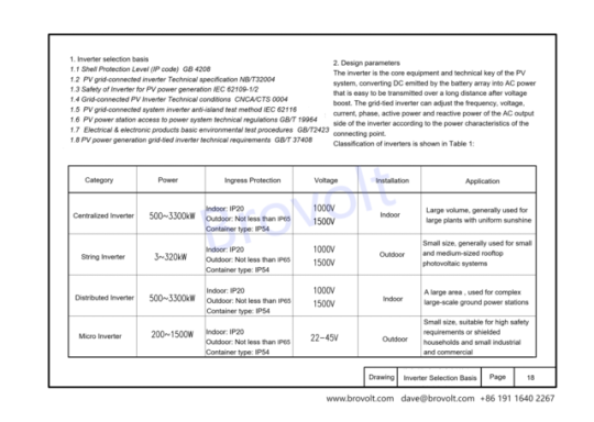
I.Inverter selection basis
1.1. "Shell Protection Level (IP code)" GB 4208
1.2. "Photovoltaic power generation grid-connected inverter technical requirements" GB/T 37408
1.3. "Photovoltaic power station access to power system technical regulations" GB/T 19964
1.4. "Electrical and electronic products basic environmental test procedures" GB/T2423
1.5. "Grid-connected photovoltaic Inverter Technical conditions" CNCA/CTS 0004
1.6. "Photovoltaic grid-connected system inverter anti-island test method" IEC 62116
1.7. Safety of Inverter for Photovoltaic power generation IEC 62109-1/2
1.8. "Photovoltaic grid-connected inverter Technical specification" NB/T32004
2. Design parameters
2.1The inverter is the core equipment and technical key of the photovoltaic system, converting the direct current emitted by the battery array into AC power that is easy to be transmitted over a long distance after voltage boost. The grid-connected inverter can adjust the frequency, voltage, current, phase, active power and reactive power of the AC output side of the inverter according to the power characteristics of the connecting point.
Classification of inverters is shown in Table 1:
2.2 Centralized inverter
The centralized inverter summarizes the DC generated by the photovoltaic module into a larger DC power and then inverts it. The power of this type of inverter is relatively large, and the single capacity is generally above 500KW. It has the advantages of large output power, mature technology, high power quality and low cost, but at the same time it has the disadvantage of insufficient MPPT tracking accuracy. It will affect the efficiency and electrical capacity of the entire photovoltaic power station when it encounters cloudy, shaded or a single series failure, and requires a dedicated room for ventilation and heat dissipation, so the variety is usually used in centralized large-scale photovoltaic power stations with uniform light
2.3 String inverter
Several groups of photovoltaic series for a separate maximum power peak tracking, and then after the inverter into the AC power grid, this type of inverter power is relatively small, single power is generally below 100KW, with the technical progress and cost reduction and efficiency demand is becoming increasingly prominent, the power gradually increased to 136KW, 175KW and other high-power products. It has the advantages of large number of MPPT, flexible component configuration, easy installation, high tracking accuracy, high power generation, fast operation and maintenance, but also has the disadvantages of slightly poor power generation quality and high cost, mainly used in small-scale household distributed power generation, small and medium-sized industrial and commercial rooftop power stations.
2.4 Distributed inverter
Distributed inverter realizes multi-channel MPPT optimization function by pre-controlling multiple MPPT optimizers, and adopts centralized inverter inverter after convergence. This type of inverter combines the advantages of "centralized inverter" and "decentralized MPPT tracking" of large-scale centralized photovoltaic inverters to achieve low cost and high reliability of centralized inverters and high power generation of serial inverters. According to the Sobi photovoltaic network, the distributed type is 2%-5% higher than the centralized power generation, and has better power quality, grid adaptability and lower system investment costs than the string inverters
2.5 Micro inverter
Micro inverter for each photovoltaic module for a separate maximum power peak tracking, and then through the new energy power generation after the inverter into the AC grid, this type of inverter single capacity is generally less than KW, with each component independent maximum power tracking control, in the case of shading or component performance differences to improve the overall efficiency, to minimize safety risks and other advantages. Its disadvantage is high price, more difficult to maintain after failure, more suitable for smaller projects.
3. Inverter selection requirements
3.1 The requirements of the State Grid for distributed photovoltaic power stations are as follows: 220V can be accessed below 8kW; 8kW~ 400kW can be connected to 380V; 400kW~6MW can be connected to 10kV. According to the characteristics of the inverter, the selection of photovoltaic power plant inverter is shown in the figure:
3.2 The roof of 10kV project is generally a large roof, a single roof arrangement of the roof capacity of up to MW, a single inverter under the same MPPT circuit of the photovoltaic module inclination, orientation and shadow occlusion is consistent, it is recommended to choose a centralized inverter.
3.3 The design of the roof photovoltaic power station is relatively complex, affected by the roof structure, size, layout, materials, bearing and shadow occlusion and other factors, need to maximize the benefits through the photovoltaic module laying and inverter selection planning. The layout of photovoltaic modules on the roof is mostly blocked or the orientation is inconsistent, in order to simplify the design, it is recommended to choose a series inverter.
3.4 The roof of the plant is mostly color steel roof, bearing limited, can not install a series of inverters, and need to meet the daily maintenance, does not affect the normal production and operation requirements, can choose a centralized inverter.
4.Inverter installation requirements
4.1. Environmental requirements
4.1.1 There should be no flammable and explosive materials in the installation environment; 1.2 Should not be installed in places accessible to children:
4.1.3 Temperature and humidity should meet the following requirements:
Maximum ambient temperature :+60℃; Minimum ambient temperature :-30℃; Maximum relative humidity :100%(non-condensing)
4.1.4 To avoid direct sunlight, direct rain and snow, extend the service life of the inverter, outdoor installation of the inverter should be set in a position that can shade the sun and rain:
4.1.5 To ensure smooth ventilation and heat dissipation of the inverter, it is appropriate to install the inverter in a ventilated environment :1.6 for 10kV series inverters or centralized inverters, the inverter should be installed in a position greater than 30m away from third-party wireless communication facilities or residential.
4.2 Installation carrier requirements
4.2.1 The installation carrier should not be flammable material:
4.2.2 The maximum bearing capacity of the carrier is >4 times the weight of the inverter.
3.Angle
4.3.1 Vertical installation or backward tilt installation of inverters (the required Angle to the ground >10°), should not be installed forward or upside down:
4.3.2 The installation height of the inverter meets the requirements of the turning radius of the cable and is convenient for personnel to operate.
4.Protectionfunctionrequirements
(1) DC input side overvoltage protection
(2) AC output side overvoltage/undervoltage protection
(3) AC overpass/underfrequency protection:
(4) DC input or AC output polarity misconnection protection
(5) AC output side phase protection
(6) DC input overload protection
(7) Output short-circuit protection:
(8) DC side back discharge protection
(9) Anti-island effect protection:
(10) The function of restoring the grid connection when the frequency voltage on the AC side returns to normal:
(11) High temperature cooling protection function:
(12) Lightning protection.
5, inverter DC input voltage requirements
(1) Under the extreme low temperature operating conditions of the photovoltaic module, the open circuit voltage of the photovoltaic series DC side is < the maximum DC input voltage of the inverter:
(2) Under extreme low temperature working conditions, the working voltage of the DC side of the PV module is < the maximum voltage of the inverter Mppt;
(3) Under the extreme high temperature operating conditions, the working voltage of the PV series DC side is > the minimum voltage of the inverter Mppt.
1.5 To ensure smooth ventilation and heat dissipation of the inverter, it is appropriate to install the inverter in a ventilated environment :1.6 for 10kV series inverters or centralized inverters, the inverter should be installed in a position greater than 30m away from third-party wireless communication facilities or residential.
2 Installation carrier requirements
2.1 The installation carrier should not be flammable material:
2.2 The maximum bearing capacity of the carrier is >4 times the weight of the inverter. The Angle is required
3.1 Vertical installation or backward tilt installation of inverters (the required Angle to the ground >10°), should not be installed forward or upside down:
3.2 The installation height of the inverter meets the requirements of the turning radius of the cable and is convenient for personnel to operate. 4
(1) DC input side overvoltage protection (2) AC output side overvoltage/undervoltage protection
(3) AC overpass/underfrequency protection:
(4) DC input or AC output polarity misconnection protection
(5) AC output side phase protection
(6) DC input overload protection
(7) Output short-circuit protection:
(8) DC side back discharge protection
(9) Anti-island effect protection:
(10) The function of restoring the grid connection when the frequency voltage on the AC side returns to normal:
(11) High temperature cooling protection function:
(12) Lightning protection.
4.Inverter DC input voltage requirements
(1) Under the extreme low temperature operating conditions of the photovoltaic module, the open circuit voltage of the photovoltaic series DC side is < the maximum DC input voltage of the inverter:
(2) Under extreme low temperature working conditions, the working voltage of the DC side of the PV module is < the maximum voltage of the inverter Mppt;
(3) Under the extreme high temperature operating conditions, the working voltage of the PV series DC side is > the minimum voltage of the inverter Mppt.
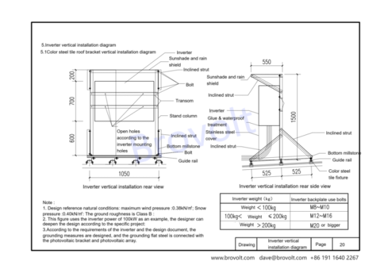
5..lnverter vertical installation diagram
5.1. This figure is suitable for vertical installation of inverters and installation of color steel tile roof brackets.
5.2. Sun shield/brace/beam/column/stainless steel shield/bottom beam/guide rail/color steel tile fixture
5.2.1 Inverter mounting holes and bolt specifications
Inverter weight <100kg Bolt M8~M10
100kg ≤ Inverter weight ≤ 200kg Bolt M12 to M16
Inverter weight >200kg M20 and above
5.3. Design reference parameters
5.3.1 Maximum wind pressure: 0.38kN/m²; Maximum snow pressure: 0.40kN/m²;
Ground roughness: Class B
5.3.2 The inverter power example is 100kW, the specific project can be further designed according to the actual situation.
Grounding measures should be taken according to the requirements of the design document, and the grounding flat steel should be connected with the photovoltaic bracket, inverter and photovoltaic array.
5.4. Other installation requirements
5.4.1 The inverter back plate must be perforated according to the installation hole positions, and secured by bolts of the corresponding specifications.
5.4.2 After the column and bottom beam are installed, waterproof and glue should be applied to ensure long-term safety.
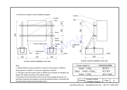
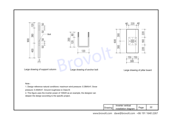
2. .Concreteroofsupportverticalinstallationdiagram
2.1. This drawing is suitable for vertical installation of inverters and vertical installation of concrete roof supports.
2.2. Mounting accessories are bolts/expansion bolts/purlins/ground copper wire/ground flat steel/post/anchor bolt
2.3.1 Design reference natural conditions: maximum wind pressure: 0.38kN/㎡; Snow pressure: 0.40kN/㎡; The ground roughness is class B.
2.3.2. This drawing uses the inverter power of 100kW as an example, and designers can deepen the design according to specific projects;
2.3.3. Design the grounding measures according to the requirements of the inverter and the design document, and the grounding flat steel is connected with the photovoltaic bracket and photovoltaic array
6. Wall installation diagram of wall-mounted inverter
6.1. This drawing is suitable for wall installation of inverters
6.2. Installation accessories include bolts, expansion bolts, beams, ground copper wires, and ground flat steel
6.3.1 Design reference natural conditions: maximum wind pressure: 0.38kN/㎡; Snow pressure: 0.40kN/㎡; The ground roughness is class B.
6.3.2. This drawing uses the inverter power of 100kW as an example, and designers can deepen the design according to specific projects;
6.3.3. Design the grounding measures according to the requirements of the inverter and the design document, and the grounding flat steel is connected with the photovoltaic bracket and photovoltaic array
0 notes
Text

Research on the electrical design of PV-Energy-storage-direct-current- flexible buildings
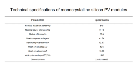
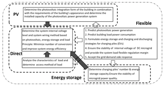
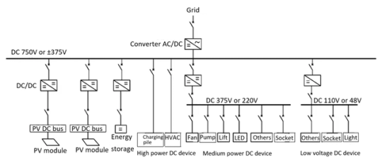
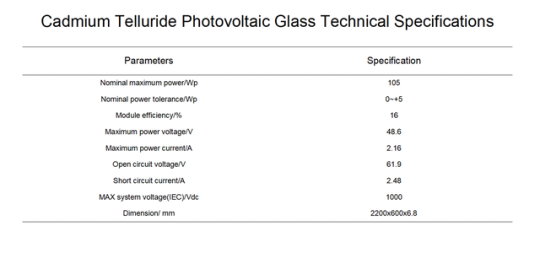
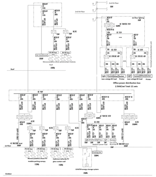
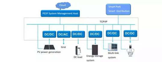
[Introduction] In view of the fact that there are few completed cases of "PV-Energy-storage-direct-current-flexible" buildings, the electrical system of PEDF buildings is quite different from the electrical system of traditional buildings. This paper intends to analyze the system design from four aspects: photovoltaic power generation system, energy storage system, low-voltage DC system and flexible control platform of "PV-energy-direct-flexible" buildings. Taking an office building as an example, this paper proposes the key points of photovoltaic component selection, self-consumption analysis method, low-voltage DC system wiring and main equipment selection, etc., for reference and reference when peers design similar systems.
1.Basic concept of PV-energy-direct-flexible building electrical system
The concept of "PV-energy-direct-flexible" was first proposed in China. "PV" refers to building photovoltaics, "energy" refers to energy storage in the building and the use of battery resources of electric vehicles in the adjacent parking lot, "direct" refers to the use of DC power supply inside the building, and "flexible" refers to the purpose of PV-energy-direct-flexible , that is, to achieve flexible power consumption and make it a flexible load or virtual flexible power supply of the power grid; the ultimate goal of the PV-energy-direct-flexible building electrical system is to change the building power system from the current rigid load to a flexible load, which can adjust the power consumption at any time according to the supply and demand relationship of the power system, rather than depending on the power consumption of each power-consuming device in the system at that time.
0 notes
Text
This atlas provides reference for architectural designers and photovoltaic system designers, and also provides photovoltaic system design and installation guidance for design units, construction units and development and construction units.
0 notes
Text
200kW 1MWH Energy Storage System
Brovolt has launched an advanced energy storage system solution designed to provide stable, efficient, and secure energy management for photovoltaic, wind power, and other renewable energy projects. The system adopts a DC1000V energy storage solution with a specification of 200KW/1.1712MWh, integrating a lithium iron phosphate (LiFePO4) battery system, Battery Management System (BMS), Power Conversion System (PCS), Energy Management System (EMS), as well as fire protection and temperature control systems, meeting the high demands for safety, reliability, and efficiency in modern renewable energy applications. Key Technical Highlights: 1.Battery System The energy storage system features a nominal voltage of 768V with lithium iron phosphate battery packs configured at 3.2V280Ah, organized in a 5P240S structure, and utilizing a forced air-cooling system. The design is simple, reliable, and easy to maintain, ensuring long-term stable operation.
Battery Management System (BMS) The system is equipped with a two-level BMS. The primary BMS monitors the real-time voltage and temperature of each individual cell and provides balancing functions. The secondary BMS manages the battery clusters, implements balancing strategies, fault diagnosis, and battery protection functions, ensuring safe operation of the entire energy storage system under various conditions. 3.Power Conversion System (PCS) The system is equipped with two 105kW PCS units, providing a maximum output power of 210kW, capable of meeting the nominal power requirement of 200kW. It ensures efficient charging and discharging while seamlessly integrating with the grid, making it suitable for different renewable energy integration scenarios. 4.Energy Management System (EMS) This energy storage solution is equipped with an integrated touch-screen EMS system that combines HMI and controller functions. The system directly interfaces with the cloud platform for remote monitoring and data analysis, supporting visual management of devices, improving operational convenience and efficiency. 5.Safety and Fire Protection Design To ensure system safety, each energy storage cabinet is equipped with an aerosol fire extinguishing system and detection devices. In the event of thermal runaway in the battery cells or component short circuits causing a fire, the system automatically activates the fire suppression system. Additionally, a sound and light alarm is installed outside the cabinet to alert personnel for timely action. Operating Strategy: This energy storage system is designed for one charge-discharge cycle per day, with a depth of discharge (DOD) ranging from 10% to 90%, and a maximum charging and discharging power of 200kW. The system will perform no more than one charge-discharge cycle per day, meeting the needs for frequency regulation and load adjustment in renewable energy projects. Conclusion: Brovolt’s new energy storage system is not only highly efficient in energy management but also optimized for safety, flexibility, and maintainability. It provides stable grid frequency regulation and peak-shaving functions for renewable energy projects such as photovoltaic and wind power, improving energy utilization efficiency and promoting sustainable development of green energy.
0 notes
Text
What can you do when the battery catches fire? All we can do is watch it burn up. This is a poor quality product. BroVolt insists on high quality products and refuses to use inferior raw materials.
0 notes
Text
Charge Characteristics of Lithium-ion Batteries
With the large-scale use of lithium-ion batteries, from electric vehicles to the current energy storage system in full swing, no matter how the external system changes or the chemical components of lithium-ion batteries improve,from LiFePO4 battery to NCM/NCA battery, the essence of lithium-ion batteries has not changed substantially, and their charge and discharge characteristics also follow a similar step curve.
Characteristics of lithium-ion batteries Lithium-ion batteries are one of the batteries with the highest energy density. Their single-cell batteries provide higher voltages and withstand larger currents, and do not require trickle charging when the battery is fully charged. However, lithium-ion batteries have no memory effect, which means that they will not "remember" the remaining power before the battery is completely exhausted, so lithium-ion batteries must be charged using a special constant current constant voltage (CC-CV) charging curve, which can be automatically adjusted according to the battery temperature and voltage level.
Charging stages of lithium-ion batteries Stage 1 Trickle Charge If the battery voltage is lower than VBATT_TC (trickle charge to pre-charge voltage threshold) (2V/cell), the IC will charge the battery with a trickle charge current of 100mA (adjustable). The trickle charge stage is usually only used when the battery voltage is below a very low level (about 2.1V). In this state, the battery pack's internal protection IC may have disconnected the battery due to deep discharge or an overcurrent event. The charger IC provides a small current (usually 50mA) to charge the battery pack's capacitor to trigger the protection IC to close its MOSFET to reconnect the battery. Although trickle charging usually only lasts for a few seconds, the charger IC still needs to integrate a timer. If the battery pack is not reconnected within a certain period of time, it indicates that the battery is damaged and the timer stops charging.
Stage 2 Pre-Charge
Once the battery pack is reconnected or in a discharged state, it enters the pre-charge stage. During pre-charge, the charger IC begins to safely charge the depleted battery at a low current level, which is usually C/10 (C is the capacity in Ah). Pre-charge causes the battery voltage to rise slowly. Its purpose is to safely charge the battery at a low current level to prevent damage to the battery until its voltage reaches a higher level.
Phase 3 Constant Current - CC
Also known as the fast charging phase, constant current charging (CC) begins after pre-charging and begins once the battery voltage reaches approximately 3V per cell (adjustable). During the constant current charging phase, the battery can safely output a higher charging current between 0.5C and 3C. Constant current charging continues until the battery voltage reaches the "full charge" or float voltage level, and then enters the constant voltage charging phase.
Phase 4 Constant Voltage - CV
The constant voltage (CV) threshold for lithium batteries is typically 3.5V to 3.65V per cell. The charger IC monitors the battery voltage during constant current charging. Once the battery reaches the constant voltage charging threshold, the charger IC switches from constant current to constant voltage regulation. Constant voltage charging begins when the charger IC detects that the external battery pack voltage exceeds the actual battery voltage in the battery pack. This is due to the presence of internal battery resistance, PCB resistance, and equivalent series resistance (ESR) from the MOSFET and single cell on the protection board PCM. The charger IC does not allow the battery voltage to exceed its maximum float voltage to ensure safe operation of the charging system.
Stage 5 Stop
During the constant voltage charging stage, when the current flowing into the battery drops below the set threshold (approximately C/10), the charger IC terminates the charging cycle. At this point, the battery is considered fully charged and charging is complete. If the charger IC's charge cutoff function is disabled, the charging current will naturally decay to 0mA, but this is rarely done in practice. Because the amount of charge entering the battery during constant voltage charging decreases exponentially (because the increase in battery voltage acts like a large capacitor), it takes a very long time to charge the battery with very little increase in capacity.
0 notes
Text
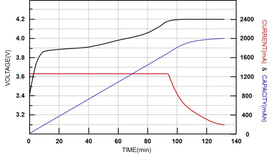
Charge Characteristics of Lithium-ion Batteries
1 note
·
View note