#arduino printed skeleton
Explore tagged Tumblr posts
Visit Tumblr Blog
Explore Tumblr blogs with no restrictions, modern design and the best experience.
Last Seen Tumblr Blogs


Fun Fact
Tumblr.com rank in the US is 25.
Text


Should Understand This condition More
Find My 3D Printer
#wheelchair#seeker of the sun#be humble#robotic neural stimulation#exoskeleton#self care#arduino printed skeleton#6figure
0 notes
Text
ok so preliminary thoughts on space marine cosplay no wood if I can help it, too much weight. multiple materials working together will be necessary first thought: plastic skeleton/frame for pieces, metal mesh for large surface shapes, worbla for surface texture? framing could possibly be done with custom 3D printed pieces, I can design those myself. metal mesh might add significant weight, but shouldn't be overwhelming. having never worked with worbla, I'm hesitant to settle on it as a solution bondo is right out, the texture isn't up to my standards/needs to be worked too much to fit my standard a cooling system of some kind, active or passive is necessary. considering how much I'll be carrying, plus the clothing underneath, plus the likelihood of me wearing a helmet for lengthy periods of time, means heat will be monstrous. ice packs might work, but I'll have a backpack as part of the suit anyways so I'm considering some different active solutions here I'd like to add some electronics, in thinking an arduino would probably get the job done, and I know enough programming and electrical work to put something decent together any thoughts?
1 note
·
View note
Text
Lab 4 - cpsc 543
This past lab had us learning the basics of a PID (proportional integral derivative) controller. What is that you might ask, well basically it’s a control loop feedback mechanism used for modulate some output.
The lab had a fair bit of setup which involved:
The PIDLibrary for Arduino
The Twiddlerino library for Arduino
A new programming environment called Processing, thats for graphical sketches.
The ControlP5 library for Processing
Some Arduino and Processing skeleton code to get things started.
What is Twiddlerino? Well formally it’s a single degree of freedom rotary haptic device. It’s better explained with a picture in my opinion.

Basically on the left you have a DC motor with a cylindrical disk attached to the drive shaft which you can interact with via your hands. Through it you can convey different haptic feedback such as resistance or guidance. In the centre you have the interface box, that houses Deumilanove board, and on the right, the power adapter.
It took a bit to get this setup to work but once going the Twiddlerino simulates a simple spring, via haptics, while through the Processing Sketch you can see it visually.
youtube
What you watch the blue wave doing on the screen is what you essentially feel through the Twiddlerino. Pretty cool I think!
So with the Twiddlerino working and the visual sketch in Processing displaying a visual representation of the haptic feedback, there were a bunch of questions to answer for different parts of the lab. I’ll do my best to go through them below.
Part 1. Run the code and try out the P controller.
The skeleton code implemented the P part of the PID, it’s what you see working in the video above.
So how did it feel? Well it felt like a spring centred around the target line. Moving slightly above or below the target line gave no resistance but as soon as you started getting to far away the Twiddler would start to push back with increasing resistance. Also like a spring you could pull it far and let it spring back and bounce around somewhat until it reaches equilibrium.
What happens when you change the target position? it moves the red line in the Processing windows graphing the position and target over time. The blue line follows the target as the P controller is attempting to keep the blue line (position) near the target position. The image below shows what happens when there is a sudden large change in the target and how the position adjusts accordingly.

What does changing the P parameter do? As you increase it, it progressively makes the spring or Twiddler feel stiffer and have more force feedback.
Do you notice any problems? If you make P to high then the position will just behave very erratically. Being unable to keep at an equilibrium and shooting wildly back and forth if disturbed to much via the Twiddler. You can see this in the video below.
youtube
Part 2. Add the D component to your controller.
Adding the D component took a little bit of code in the Arduino skeleton code and a few graphical changes in the Processing sketch. Below is it in action with my varying the D value to see the results.
youtube
How does this change the behaviour of the Twiddlerino? - Controls the spring-back force so it doesn't overshoot the target much, reducing the bouncing back and forth of the Twiddler around the target.
Are there any problems? If you put the D value to high it has a very slow return back to the target as seen near the end of the video.
Part 3. Add the I component to your controller.
I didn’t get a good video with a larger P value while adjusting I, but the second half of this video shows me playing around with different I values.
youtube
How does this change the behaviour of the Twiddlerino? It will try and bring the position as close to the target as possible, basically trying to minimize any steady state error.
Can you create a stable system that reaches the target? I did eventually but didn’t get a good video of it :( Basically i put P around 6, I around 0.5, and D around 0.25. And it made roughly a stable system that returned to the target fairly quickly, with minimal bounce-back, and stuck very close to the target.
Part 4. Implement a virtual wall, as a one-sided spring (like Step 1) but active only for θ>0.)
I put the following code at the bottom of the main loop() // implement virtual wall if (pos > 0) { // do nothing SetPWMOut(0); } else { SetPWMOut(PWMOut); }
And after tweaking the P and D values a bit, got a pretty decent feeling of “hitting” a wall.
youtube
What happens? Anything above the target (greater than zero), when the target is set to zero is free space, outside the wall. While as soon as you hit the wall (i.e. zero) the spring does an abrupt push back, making it feel like hitting a wall.
By adding/tweaking PID parameters, can you make it more wall-like? The video above shows a P value of around 8 and a D value of around 0.08 which simulated a wall fairly well in my opinion.
Part 5. Play with the controller update rates, and with introducing delays.
By edditing the myPID.SetSampleTime(1); //every 1 ms line in the setup() routine. I was able to play around with different update rates.
How does this change the system? I missed getting a video of this, but i cranked the rate up to 10 second and it let me get the position well into the wall before it registered that I was in there.
What happens if you sample faster or slower? Faster gives you better resolution, so you know you’ll definitely hit the wall the moment you get to zero. While making it larger can have it so that your position can get in the wall before the system picks up you’ve passed zero.
Can you make the interrupt service routine run faster, and see better performance that way? Sampling at 1ms seemed pretty optimal, and when I reduced this to less, it didn’t really seem to make a difference. It only got worse the higher the value went.
Part 6. Think about different ways of timing the loop (polling "run as fast as you can", vs. clocked "wake up at a specified time").
Here we were to look at 3 Arduino sketches; Blink, BlinkWithoutDelay, and FlashLED.
What are the impact of each of these?
For Blink you're essential blocking the code and causing the whole program to stall until it completes.
For BlinkWithoutDelay you're essentially introducing a state machine and keeping tack of the time since last blink. So instead of blocking code for each pass of the main loop and getting held up by delay(), as in Blink, you just execute the code when a certain length of time has passed. Freeing up the thread to execute other code.
I remember doing something similar for this in lab 3 where I had to have a servo and dc motor work independent of each other and not block each others execution.
For FlashLED, you’re taking advantage of the built in timers on the Arduino, there typically tied to pins so you might interrupt some of the Arduinos Pulse Width Modulation. But otherwise you can use them to trigger code at exact time intervals.
Which method is implemented in the sample code? In the start of the main loop it implements the state machine (keeping track of time since last execution) before printing out the position variable. Set to print out every 10 ms. But also the myPID.Compute(); probably implements a similar state machine.
Can you make a theory about impact on the Twiddlerino sketch, and test it? I think if you switch this to polling, i.e. removing the time tracking it might just tie up the thread and not let anything else run.
Here’s what I tried.
At the beginning of main loop() comment out this block of code, except for the println() statement.
//Write position every updateInterval ms // long t = millis(); // long dt = t - last_time; // if (dt >= updateInterval) // { Serial.println((int)pos); // last_time = t; // }
Here’s a video of what happened. (click link)
https://youtu.be/m9TZ02gG5XM (I think I reached the number of embedded videos in Tumblr limit o.O)
It seems to just not let anything else respond. I think you're basically tying up the process for the code and if you leave only the Serial.println((int)pos); uncommented; letting nothing else run.
Overall this lab was a great learning experience, and how to get a control loop feedback mechanism working. This is the first time I’ve ever worked with a PID controller and found that it’s nice, clean, and simple to implement. I guess that’s why there still so heavily used.
Now next weeks lab will be really interesting as it’s time to start using our newfound PID skills in a physical creation of our choosing.
Until next time!
0 notes
Text
PComp Week 7: Halloween Midterm Part 1
This week we completed our Halloween midterm. The assignment was to make an interactive Halloween display with physical controls using serial/analog/digital communication. I was partnered with SJ and two weeks ago, we started by getting together and brainstorming some ideas. Here are a few of the ones we came up with:
Cauldron you can put things in or take things out of → triggers something on a computer screen or a sound?
Game with eyeballs? If you pick eyeballs up there’s a light sensor underneath and it changes an animation on the computer or a sound. Maybe something two people could play together?
Ghost that jumps out at you and is motion activated. Or candy shoots out or falls on people?
Competition to make a coffin open and a skeleton pop up
Light up jack o'lantern display
Draw out pumpkin with LEDs using p5 → “digital pumpkin carving”
We both liked the last one best because from the user side, we thought it would fun (SJ didn’t want to make something scary :)), engaging and easy to use and from our side, we would learn about a new input (potentially a joystick to control the p5 drawing) and new type of output (LED display). I also liked the similarity to the project a guy has to get people all over the internet draw sheep. We could also create idea #5 if we took pictures of each pumpkin and put them together to create a huge display!
Inspiration:

Photo: A display of pumpkins I saw in Chicago one year
First, we sketched out our idea:

Within 15 minutes, SJ had created a p5 sketch to map to the matrix:
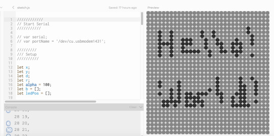
We asked a few residents and our professor (thanks, Jeff!) about their impressions of the technical side of the idea and if it fit the assignment requirements. After looking at their suggestions online and googling a few other things, we decided on a 32x32 LED matrix that is compatible with Arduino (takes 5V was important to confirm!) We considered using the programmable LED NeoPixel strips to make our own matrix, but we decided that that would be too complicated for this short project.
We took a trip to Tinkersphere and picked up the LED matrix, connecting wires and joystick. The matrix didn’t come with a datasheet, but we had found an guide and library on Adafruit. When we got back to ITP and started reading the instructions on how to connect the matrix to the Arduino, we realized that there is also a $5 chip you can buy to avoid having to do all the wiring yourself! This was a lesson in why it’s better to read the datasheet/guide carefully ahead of time!
We decided to forge ahead and connect the matrix with our own wires. We didn’t have all the right colors, so it ended up looking a little messy (we used a pen to color a white wire red…). But, it worked! We downloaded the test code from Adafruit and our matrix lit up with beautiful rainbow colors!


youtube
Establishing Communication from P5 to Arduino
The next step was figuring out how to send the p5 data to the Arduino and have that map to the LED matrix. We emailed one of the residents (thanks, Seho!) to get some pointers in which direction we might go. He explained that we could either send one number for each LED or send coordinates. We hadn’t done serial communication with sending multiple signals yet or parsing data, so we decided to first do that labs on our own, and meet again to compare what we had come up with.
Turning on and off an LED with serial output from p5:
1. Set up breadboard

2. Establish serial communication through arduino:
youtube
3. Add in serial communication from p5:
youtube
Applying the lab to our matrix:
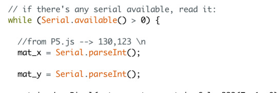
Because we wanted to send multiple coordinates in a drawing, at first I tried sending a whole array from p5 to the Arduino. I figured once I sent the array I could have the code in Arduino loop through it and light up the corresponding LEDs. But whenever I opened the serial monitor, only part of the array seemed to get through and worse it wasn’t consistent which parts appeared.
Since SJ and I were both having trouble sending the data correctly, we decided to book office hours with a resident (Hayley!). Because we were getting weird output, Hayley helped us first establish that we were sending the data we thought we were by controlling an LED through digital communication with keys in p5 (basically another version of the lab!). Even though the data didn’t look right in the serial monitor, the LED lit up, so we knew we were on the right track.
Then we discussed with her the best way to send the coordinates. She recommended sending individual coordinates in a string instead of an array and then parsing them in Arduino. Haley also told me that using the Arduino serial monitor with p5 doesn’t work, so I’d have to send back the signal to p5 from Arduino and see it in the console there - which is probably why I was getting weird output before in the Arduino serial monitor!
I looked into parsing strings on my own and started trying the strtok() and indexOf() functions, but after having trouble getting it to work (and after a troubleshooting session with my friend Matt that didn't yield the results we wanted), I decided to go to the PComp help session. Hayley was there again and showed me the parseInt() function. By putting a comma in the middle of the two numbers, we made this function grab the strings before and after and put them into different variables for the x coordinate and y coordinates.
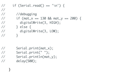
We first tested that this was working correctly by sending numbers in the serial monitor, then sending hard coded numbers from p5 and then sending the mouseX and mouseY positions from p5. In the first iteration, we checked that we had the correct numbers first by lighting up an LED and later once we saw that this was working by having Arduino send the variables back to p5 and print them.
The end code looks super simple now that we have it. The hardest part was figuring out how to send and read the data because there are multiple ways of doing it on each end and there is not one “right” way. This also taught me about different ways of troubleshooting with hardware and digitally and the importance of doing this troubleshooting at the beginning and in small steps - it’s much easier to do that than to work backwards from a complicated code that isn’t working!
Arduino to LED Matrix
Now that we had established that p5 was sending the correct numbers (the mouseX and mouseY positions) and Arduino was getting the correct numbers, it was time to add the LED matrix into the equation. I tried plugging our wires back in, but the display didn’t light up correctly.
SJ and I talked and decided we needed better wires, so the next day he picked some up from Tinkersphere. We plugged them all back in and our board lit up beautifully!


Our goal was eventually to send the mouseX and mouseY coordinates, so we started by taking the following steps:
1. Run the matrix test code - this was easy now that we had the wires working!
2. Use Arduino code to light up one LED at a time by hard coding the number - also simple!
3. Use hard coded variables in Arduino to light up the LED position of our choice - no problem!
4. Light up an LED of our choice using the serial monitor in Arduino to update the variable values, simulating a signal from p5 - this worked right away since we had tested it before without the LED matrix.
5. Send a hard coded value from p5 to change the value of the xpos and ypos variables in Arduino. At first we thought that this wasn’t working when we tried sending (20, 50), but then we realized we were drawing off the grid since the grid was only 32x32 and our canvas was 400x400.
youtube
6. Replace the hard coded values in p5 with mouseX and mouseY to send to Arduino. This worked and we were so excited, but there was also a huge delay in the LEDs lighting up. We were using console.log in p5 to see what we were sending to Arduino and we kept seeing way too much information being passed back and forth, so we thought this might be the problem.
First, the coordinates were being sent multiple times every time we clicked and we also received back multiple messages from Arduino for the one coordinate we had sent. We first looked around in the p5 code for a way to prevent the coordinate from being sent multiple times - was it because draw() was looping multiple times? We tried moving the code to setup, but then nothing appeared on our sketch. Then I tried commenting out the serial.write in Arduino that was sending the message back to p5 and this got rid of the delay! I think by sending this information back to p5, the Arduino couldn’t get the next incoming serial communication from p5.
youtube
In the video above you’ll also see SJ trying to keep the mouse within 32,32 in the p5 sketch. After this we re-mapped the p5 output to be a 32x32 grid since the p5 sketch was still a 400x400 canvas. Once we did that it worked!
SJ made a drawing to show how we felt about our creation:

Video here - it won’t embed because I have too many videos in this post already: https://www.youtube.com/watch?v=0n_CPKz3eW4&feature=youtu.be
I’ll share the finishing touches and final reflections in part 2!
0 notes
Text
“You’ve Got Mail!” for the 19th Century
As mailboxes proliferated, inventors rushed to devise electrically enhanced versions
Photo: National Postal Museum/Smithsonian Institution
Photo: National Postal Museum/Smithsonian Institution
During the 1870s and ’80s, inventors filed more than a dozen patent applications in the United States for electrical improvements to letter boxes. But why did mailboxes and letter slots, surely among the simplest mechanical devices, have to be electrified? It was primarily a matter of convenience, for people who wanted to know exactly when the mail had arrived and didn’t want to waste time checking.
Free home delivery of the mail had begun in the United States in 1863, but mailboxes were not yet standard. Instead, a postman would knock on the door (perhaps with a handheld wooden knocker), wait for someone to answer, and then hand over the mail. If no one was home, the carrier returned later or the next day. Although this created great trust in the system, it wasn’t very efficient. In 1909, postal officials calculated that on a typical day, carriers made 360 stops and spent an average of 15 seconds per delivery, or an hour and a half a day, simply waiting.
Photos: National Postal Museum/Smithsonian Institution
A Smarter Mailbox: Ephraim E. Weaver’s electric mailbox [front and interior shown here] came with a key that the delivery person could use to ring a bell, signaling that a package had arrived.
Beginning in the 1880s, the U.S. Post Office Department began encouraging people to install a mailbox or letter slot, although they didn’t become a requirement until 1923. (For a nice concise history of the U.S. Postal Service, see The United States Postal Service: An American History 1775–2006 [PDF].)
And so, many of the early patents for electrical indicators for letter boxes tried to replace or augment the postman’s knock. Inventor Henry R. David thought that large office and apartment buildings in cities had a particular problem. His 1875 U.S. patent [PDF] detailed a system of circuits that would inform people in far-flung corners of the building that mail was waiting for them at the main entrance.
Many of the electric letter boxes, including the device that William H. Rodgers described in an 1879 patent [PDF], worked by closing a battery-powered circuit when the postman deposited letters in the box. The circuit would ring a bell inside the house. Sometimes, though, the weight of a single letter wasn’t enough to engage the circuit, as Rodgers noted in another patent that same year [PDF]. The inventor’s improved design engaged the circuit when the postman opened the box. The circuit, after ringing the distant bell, stayed locked in the on position, until the box was reopened. Obviously, Rodgers never imagined that pranksters might repeatedly open and close the box to set off the mail bell.
Charles H. Carter did spot this problem, claiming in his 1880 patent [PDF] that owners of such mailboxes were inconvenienced by “any person raising the lid or inserting any unimportant circular.” In his design, the postman would sound an alarm by means of a skeleton key. Unfortunately for Carter, the Post Office Department issued standards that required mailboxes to, among other things, allow carriers to withdraw and deposit mail “without delay.” A design that required a separate key to indicate delivery was unlikely to be approved.
Carter applied for another mailbox patent that introduced a visual indicator [PDF]. Once a letter closed the circuit, a configuration of electromagnets would expose a flap labeled “mail.” Carter suggested that the flap could also have numbers or other visual cues to call attention to the change in status.
Despite the many patented designs for electric mailboxes, Alice H. Ewing clearly believed there was room for improvement when she applied for a U.S. patent in 1915. Patent 1,228,193 [PDF], issued to Ewing two years later, opted not for a bell or flap but for an electric light. A convenient push button next to the light would reset the circuit.
A great benefit of reviewing the history of invention through patents is that all of the technical details are well documented. But a century or more after the fact, historians often struggle to determine whether a particular idea was ever put into production, unless there is additional supporting evidence. In the case of Ephraim E. Weaver’s 1885 patent [PDF], a surviving mailbox does exist [top photo], at the Smithsonian National Postal Museum, in Washington, D.C. (Full disclosure: I used to work as a curator at the museum.) Weaver’s patent was for an indicator for items that didn’t fit in the box and thus didn’t trigger the bell. His electric mailbox came with a key that the delivery person could use to close the circuit and ring the bell.
The box in the museum’s collection doesn’t conform exactly to its patent drawing. Curator Lynn Heidelbaugh reports that it has no external handle like the one labeled “E” in the patent drawing below:
Image: U.S. Patent and Trademark Office
Change of Plans: Weaver’s patent for his electric mailbox included an external handle (which he called a “circuit-closing key”), but the actual mailbox didn’t have one.
For now, the inconsistencies will remain a mystery because this particular mailbox was found in the museum’s collections without any associated information. Curators don’t know where it was used or for how long, or whether its owners found it useful. Just as there are limits to the information that can be gleaned from a patent, physical evidence doesn’t always want to give up its story either.
Although electric mailboxes never became mainstream, the idea has recently resurfaced as a playful exercise to teach basic circuit design. For example, Electronics Hub, a website that posts DIY projects and tutorials, has an Electronic Letter Box Project Circuit that uses blinking LEDs as the indicator. Instead of physically closing a circuit, as all of the 19th-century inventions did, this one uses an LDR (light dependent resistor). When a letter blocks the photoresistor, the circuit registers that you have mail.
SparkFun, a company dedicated to electronics literacy, upped the ante with an interactive letterbox for Valentine’s Day cards. It relies on an infrared transmitter to count the number of letters that pass through the mail slot. Upload a bit of code to your Arduino, and the LED counter shows how many letters have been received.
Meanwhile, the U.S. Postal Service has introduced Informed Delivery, which sends customers scanned images of the letters they can soon expect along with notifications of packages. Multiple people at the same address can sign up for individual notifications. The service isn’t yet available everywhere, and it’s not always 100 percent accurate. Critics of the system say it poses potential security risks.
Personally, I still love walking down my driveway to check my mailbox. And on sunny days, when I am looking to procrastinate, I have no problem making that trip more than once. Compare that to my first email account, which currently has over 106,860 unread messages. My work email inbox is marginally better, with 6,067 unread messages. Long ago I turned off any digital indicator announcing the arrival of a new email. There is simply too much. In the prescient patent of Charles Carter, I too prefer not to be annoyed by all those “unimportant circulars.”
An abridged version of this article appears in the June 2018 print issue as “A Better Mailbox.”
Part of a continuing series looking at photographs of historical artifacts that embrace the boundless potential of technology.
About the Author
Allison Marsh is an associate professor of history at the University of South Carolina and codirector of the Ann Johnson Institute for Science, Technology & Society there.
“You’ve Got Mail!” for the 19th Century syndicated from https://jiohowweb.blogspot.com
0 notes
Text
Eleven Years In, Edmonton’s Transcend Coffee Continues To Grow
Poul Mark
Transcend Coffee occupies a venerable place in Edmonton’s coffee scene. The company’s flagship location—a combination coffee bar and roastery in an industrial area south of the city’s trendier neighbourhoods—opened in July 2006 and was almost certainly Edmonton’s first Third Wave cafe. And one could make a convincing case that it was Transcend baristas who first introduced Edmontonians to rosetta-bedecked cappuccinos and tasting notes for coffee that, the baristas went to great lengths to explain, were not “flavoured,” just complex.
Owner Poul Mark—formally trained as a lawyer—was self-educated in terms of coffee. At the beginning, he didn’t even have a skeleton crew working with him. “I was the barista,” he smiles wryly, “I was the cashier.”
Ironically, Mark wasn’t even certain he wanted to serve coffee, much less introduce a new form of coffee culture to the capital of Alberta. The original plan was to open a wine and coffee bar, but the industrial space that Mark had become interested in wasn’t appropriate. Not to be deterred, Mark homed in on the possibilities of pure, unaided, unadulterated coffee.
“I was more interested in the notion of building community and needed a place,” he says. “Coffee is this thing that people gather around.” A lot has changed since those early days (“we’re better at it,” Mark laughs), but building community is still a priority—evidenced in the company’s Garneau cafe (next to an independent theatre and a poutine place just a few blocks off the University of Alberta campus), and its most newly opened location in the Ritchie Market.
His desire for community—and growth—was motivation enough for Mark to start roasting. “Obviously the focus has always been on quality,” Mark says of his company’s established sourcing program. His main challenge, he says, has been in building long-term relationships with growers, many of whom work small farms from which Transcend buys green beans directly.
As a small-scale buyer with high standards, Transcend has taken on the twofold task of educating its customers about coffee as a product that varies with the year and environment, while at the same time encouraging farmers to produce the calibre of green coffee that boutique companies will pay a higher price for. Mark says that this kind of dialogue with farmers is getting more and more difficult as farmers face mounting pressure from the global economy on one hand and climate change on the other.
Nevertheless, the roasting side of Transcend’s business has doubled in the last two years. The company roasts about 160,000 pounds of coffee a year and supplies cafes and retailers across Canada.
Eleven years in, Mark’s once one-man operation is one of a plethora of local coffee companies that form a small but vigorous community servicing a growing market for a type of coffee experience that was virtually non-existent in Edmonton a decade ago. And now that he’s got a whole team of people to run the show, he finds he’s more effective behind the scenes. “I’m a classic entrepreneur in the truest sense,” he says. “I dream up ideas.”
Mark’s developing business philosophy is evident in the company’s current physical manifestations: two cafes in young, mixed residential and commercial neighbourhoods that have plenty of pedestrian traffic and a strong sense of community to support them.
And Transcend’s newest location, a cafe/roastery in the new Ritchie Market, arrived on the scene this March, just ten blocks north of Mark’s original roastery (now closed). Transcend Ritchie is one of several businesses occupying places in an open-concept marketplace that will soon include a cycling store, brewery, butcher, and restaurant. The building—a high-ceilinged, many-windowed take on Edmonton’s favourite type of architecture, the brutalist box—features a large cafe space, with Transcend’s bar and Velocity Cycle on one side, Acme Meat Market’s cold case on another, and the soon-to-open brewery/restaurant visible through glass walls on the third. Transcend’s hulking orange Probat roaster has been installed in one of the front windows, and roasting operations can be observed from both inside and outside.
Similar to Transcend Garneau, the Ritchie cafe is minimalist and vaguely industrial. Under a canopy of exposed beams and pipes, small potted plants and succulents grace blonde wood tables and two long counters fully equipped with outlets for the laptops that nearly everyone in the cafe is using. Exposed copper, steel, and concrete complement the view of both Transcend’s roasting operation and the banks of brewing tanks on the brewery side of the building. There’s limited patio seating outside, where customers can enjoy Ritchie’s lively sidewalk community while they sip their coffee. In the women’s bathroom, however (I didn’t venture into the men’s), both the walls and the floor are covered in a Wes Anderson-esque pattern of pastel tiles that is surprisingly soothing to be surrounded by.
Transcend has moved away from its old purist approach here, and at Ritchie, baristas serve up Jagasilk matcha, cascara tea, flavoured lattes, and even milkshakes along with FETCO– and Moccamaster-brewed coffee and cappuccinos. Espresso is pulled on a three-group Victoria Arduino Black Eagle. The state-of-the-art machine features, among other perks, built-in scales and the capability to electronically sync with a grinder, making it easier to implement a standard for dialing-in based on a set ratio of ground beans to liquid espresso. Steaming and pouring takes place on the Modbar unit installed in the front bar. House pastries, including cookies, banana bread, and croissants are displayed in a glass case underneath the point of sale.
Transcend Ritchie has enjoyed an enthusiastic welcome from both residents of the surrounding area and from coffee drinkers across the city. The cafe is steadily busy; at times it’s tricky to find a place to sit. “Given the reception Ritchie has had from the community,” Mark says, “we’ve thought about replicating this.”
Whatever the future holds for Transcend, the move the company has already initiated—away from trendy shopping districts and toward cafes embedded in the communities where Edmontonians actually live and work—can only guarantee its legacy as a forerunner of the city’s cafe culture.
Transcend Coffee’s Ritchie Market Café And Roastery is located at 9570 76 Avenue NW, Edmonton. Visit their official website and follow them on Facebook, Twitter, and Instagram.
Lizzie Derksen is a Sprudge contributor and print publisher based in Edmonton, Alberta. Read more Lizzie Derksen on Sprudge.
Photos by Lizzie Derksen. Top photo courtesy of Transcend Coffee.
The post Eleven Years In, Edmonton’s Transcend Coffee Continues To Grow appeared first on Sprudge.
seen 1st on http://sprudge.com
0 notes
Text
“You’ve Got Mail!” for the 19th Century
As mailboxes proliferated, inventors rushed to devise electrically enhanced versions
Photo: National Postal Museum/Smithsonian Institution
Photo: National Postal Museum/Smithsonian Institution
During the 1870s and ’80s, inventors filed more than a dozen patent applications in the United States for electrical improvements to letter boxes. But why did mailboxes and letter slots, surely among the simplest mechanical devices, have to be electrified? It was primarily a matter of convenience, for people who wanted to know exactly when the mail had arrived and didn’t want to waste time checking.
Free home delivery of the mail had begun in the United States in 1863, but mailboxes were not yet standard. Instead, a postman would knock on the door (perhaps with a handheld wooden knocker), wait for someone to answer, and then hand over the mail. If no one was home, the carrier returned later or the next day. Although this created great trust in the system, it wasn’t very efficient. In 1909, postal officials calculated that on a typical day, carriers made 360 stops and spent an average of 15 seconds per delivery, or an hour and a half a day, simply waiting.
Photos: National Postal Museum/Smithsonian Institution
A Smarter Mailbox: Ephraim E. Weaver’s electric mailbox [front and interior shown here] came with a key that the delivery person could use to ring a bell, signaling that a package had arrived.
Beginning in the 1880s, the U.S. Post Office Department began encouraging people to install a mailbox or letter slot, although they didn’t become a requirement until 1923. (For a nice concise history of the U.S. Postal Service, see The United States Postal Service: An American History 1775–2006 [PDF].)
And so, many of the early patents for electrical indicators for letter boxes tried to replace or augment the postman’s knock. Inventor Henry R. David thought that large office and apartment buildings in cities had a particular problem. His 1875 U.S. patent [PDF] detailed a system of circuits that would inform people in far-flung corners of the building that mail was waiting for them at the main entrance.
Many of the electric letter boxes, including the device that William H. Rodgers described in an 1879 patent [PDF], worked by closing a battery-powered circuit when the postman deposited letters in the box. The circuit would ring a bell inside the house. Sometimes, though, the weight of a single letter wasn’t enough to engage the circuit, as Rodgers noted in another patent that same year [PDF]. The inventor’s improved design engaged the circuit when the postman opened the box. The circuit, after ringing the distant bell, stayed locked in the on position, until the box was reopened. Obviously, Rodgers never imagined that pranksters might repeatedly open and close the box to set off the mail bell.
Charles H. Carter did spot this problem, claiming in his 1880 patent [PDF] that owners of such mailboxes were inconvenienced by “any person raising the lid or inserting any unimportant circular.” In his design, the postman would sound an alarm by means of a skeleton key. Unfortunately for Carter, the Post Office Department issued standards that required mailboxes to, among other things, allow carriers to withdraw and deposit mail “without delay.” A design that required a separate key to indicate delivery was unlikely to be approved.
Carter applied for another mailbox patent that introduced a visual indicator [PDF]. Once a letter closed the circuit, a configuration of electromagnets would expose a flap labeled “mail.” Carter suggested that the flap could also have numbers or other visual cues to call attention to the change in status.
Despite the many patented designs for electric mailboxes, Alice H. Ewing clearly believed there was room for improvement when she applied for a U.S. patent in 1915. Patent 1,228,193 [PDF], issued to Ewing two years later, opted not for a bell or flap but for an electric light. A convenient push button next to the light would reset the circuit.
A great benefit of reviewing the history of invention through patents is that all of the technical details are well documented. But a century or more after the fact, historians often struggle to determine whether a particular idea was ever put into production, unless there is additional supporting evidence. In the case of Ephraim E. Weaver’s 1885 patent [PDF], a surviving mailbox does exist [top photo], at the Smithsonian National Postal Museum, in Washington, D.C. (Full disclosure: I used to work as a curator at the museum.) Weaver’s patent was for an indicator for items that didn’t fit in the box and thus didn’t trigger the bell. His electric mailbox came with a key that the delivery person could use to close the circuit and ring the bell.
The box in the museum’s collection doesn’t conform exactly to its patent drawing. Curator Lynn Heidelbaugh reports that it has no external handle like the one labeled “E” in the patent drawing below:
Image: U.S. Patent and Trademark Office
Change of Plans: Weaver’s patent for his electric mailbox included an external handle (which he called a “circuit-closing key”), but the actual mailbox didn’t have one.
For now, the inconsistencies will remain a mystery because this particular mailbox was found in the museum’s collections without any associated information. Curators don’t know where it was used or for how long, or whether its owners found it useful. Just as there are limits to the information that can be gleaned from a patent, physical evidence doesn’t always want to give up its story either.
Although electric mailboxes never became mainstream, the idea has recently resurfaced as a playful exercise to teach basic circuit design. For example, Electronics Hub, a website that posts DIY projects and tutorials, has an Electronic Letter Box Project Circuit that uses blinking LEDs as the indicator. Instead of physically closing a circuit, as all of the 19th-century inventions did, this one uses an LDR (light dependent resistor). When a letter blocks the photoresistor, the circuit registers that you have mail.
SparkFun, a company dedicated to electronics literacy, upped the ante with an interactive letterbox for Valentine’s Day cards. It relies on an infrared transmitter to count the number of letters that pass through the mail slot. Upload a bit of code to your Arduino, and the LED counter shows how many letters have been received.
Meanwhile, the U.S. Postal Service has introduced Informed Delivery, which sends customers scanned images of the letters they can soon expect along with notifications of packages. Multiple people at the same address can sign up for individual notifications. The service isn’t yet available everywhere, and it’s not always 100 percent accurate. Critics of the system say it poses potential security risks.
Personally, I still love walking down my driveway to check my mailbox. And on sunny days, when I am looking to procrastinate, I have no problem making that trip more than once. Compare that to my first email account, which currently has over 106,860 unread messages. My work email inbox is marginally better, with 6,067 unread messages. Long ago I turned off any digital indicator announcing the arrival of a new email. There is simply too much. In the prescient patent of Charles Carter, I too prefer not to be annoyed by all those “unimportant circulars.”
An abridged version of this article appears in the June 2018 print issue as “A Better Mailbox.”
Part of a continuing series looking at photographs of historical artifacts that embrace the boundless potential of technology.
About the Author
Allison Marsh is an associate professor of history at the University of South Carolina and codirector of the Ann Johnson Institute for Science, Technology & Society there.
“You’ve Got Mail!” for the 19th Century syndicated from https://jiohowweb.blogspot.com
0 notes