
Don't wanna be here? Send us removal request.
Statistics
We looked inside some of the posts by archieb303-physical-computing and here's what we found interesting.
Average Info
Notes Per Post
1
Likes Per Post
1
Reblog Per Post
0
Reply Per Post
0
Time Between Posts
7 days
Number of Posts By Type
Text
9
Photo
1
Last Seen Tumblr Blogs


Fun Fact
The “We are the 99%” Tumblr blog became the slogan for the Occupy Wall Street movement.
Text
Personal Project 8 - All Components Together + Serial
Components
1x Arduino UNO w/ USB Cable 1x Breadboard 1x Momentary Switch, Red 1x Potentiometer, Dial 1x Liquid Crystal Display 1x 10k Ohm resistor M to M wires to connect components
Description - Display, Button, Dial
In conjunction, each of the components work in a similar function as they have done in previous experiments. The LCD and momentary switch are set up in the same way as the previous post, the button sending input to pin D10, and the LCD being wired to fix the issue posed in Post 7, avoiding the PWM pin and using pin 12 instead.
Description - Application, Serial Communication
The application is unfinished for this version, simply due to time constraints. After carrying out research on using Arduinos as a HID, the main intent of this project, I discovered a library for Arduino that enables a board like an UNO to replicate a HID, as they are not natively able to do so. This requires burning a new bootloader onto the Arduino's secondary chip, which has a risk of bricking the chip entirely, which disable USB data transfer and significantly reduce the boards functionality. I discovered this risk quite late into development, and had to change course to use serial data communications to send commands to the windows forms app instead.
This meant that I had to change the way the application worked significantly, as it now had to handle serial communication as well as sending keystrokes. Both of these functions would be complex additions, on top of having to change how the shortcut data would stored. Initially the idea was to have the data stored in a header file, which could be updated and reuploaded to the board via the app. This changed to the data being stored on the users PC and the serial port communication handling the commands from the Arduino within the application.
Evaluation
Overall, I'm quite happy with the physical creation side of this project, however the application has left a lot to be desired, as it is mostly unfinished; more of a collection of concepts and ideas that would work, but have not be executed upon. The physical side has allowed me to expand my knowledge of Arduino programming, electronics, and serial based communication, while the application side has given me the opportunity to experiment with a new tool, which is something I may experiment with in the future.
I believe that there would be a market for a product like this, a more complex version of a stream deck. The surface dial is a similar product/accessory to Microsoft's surface series computer and has a significant number of functions.
To improve upon the design, a better physical form factor would be needed, something similar to a stream deck in format, as well as an actual method of programming it.
Evaluation/Demonstration Video
The video demonstrating the current functionality
Files
Arduino Sketch files, as well as test Winforms applications can be found zipped here.
0 notes
Text
Personal Project 7 - Momentary + LCD
Components
1x Arduino UNO w/ USB cable 1x Momentary Switch 1x LCD Display 1x 10k Ohm Resistor 1x Breadboard M to M Wires to connect components
Description
The next significant step in the project development, and the one with the most struggles during its development, was integrating the pre-existing Momentary switch and LCD code, into 1 functional system.
The main issue I encountered during this was the original way that I had wired the momentary switch drew too much power away from the LCD, causing it to dim significantly when the momentary switch was pressed. This was solved by using a 10k ohm resistor on the falling edge of the switch; i.e. the ground pin is connected to ground via the resistor.
Additionally, I had changed the way I was wiring the LCD, with the VO pin going to 9 instead of 1, this is to allow for serial data to be used uninterrupted, which will be important for the final version of the project. This caused an interesting issue that is shown in the short video below. It would happen at random, and would be solved temporarily by resetting the Arduino or unplugging the USB cable and plugging it back in again. However this fix was also inconsistent.
This I believe is caused by the VO pin being plugged into a PWM pin, marked on the Arduino with a '~', as when I changed it to digital pin 12, the issue was resolved.

This is the layout of the wiring for the momentary switch + LCD experiment. The custom characters on the screen are vestiges from a previous experiment, as is the potentiometer, it is just there to make the image based on that old code consistent, as calling an analogue pin for data when there is nothing connected, as the following line does, can causes inconsistencies in the display.

The momentary switch, at this point, did not have any method of limiting a function to a one time activation, and thus the number displayed increased as long as the button was held.
This issue was solved using a boolean variable as an extra condition for the function being run.

Code
#include <LiquidCrystal.>
//#include "layoutSettings.h" //old header file was going to be used to store the shortcut data
LiquidCrystal lcd(2, 3, 4, 5, 6, 7); //Parameters: (rs, enable, d4, d5, d6, d7)
//constants: const int potPin = A0; // input pin for dial const int buttonPin = 10; // output pin for momentary switch, keyswithc proxy
//variables: int value; //saves analogue value int buttonState = 0;
int test; //test var for momentary
bool buttonBool; // used for single use of function w/ momentary switch bool seg1Activated = false; bool seg2Activated = false; bool seg3Activated = false; bool seg4Activated = false;
//custom characters: byte cornerEmpty[] = { B00000, B00000, B00000, B10000, B10000, B10000, B10000, B11111 };
byte cornerFull[] = { B00111, B00111, B00111, B10111, B10111, B10111, B10000, B11111 };
byte midEmpty[] = { B00000, B00000, B00000, B00000, B00000, B00000, B00000, B11111 };
byte midFull[] = { B11111, B11111, B11111, B11111, B11111, B11111, B00000, B11111 };
void setup() { //initialise test variable test = 0;
seg1Activated = false; seg2Activated = false; seg3Activated = false; seg4Activated = false;
//button setup // initialize the button pin as an input: pinMode(buttonPin, INPUT);
//initialise display size lcd.begin(16, 2); //custom lcd chars lcd.createChar(1, cornerEmpty); lcd.createChar(2, cornerFull); lcd.createChar(3, midEmpty); lcd.createChar(4, midFull);
//contrast analogWrite(12, 30); // writes value 30 to pin D12
//serial Serial.begin(9600);
}
void loop() { value = analogRead(potPin); // potPin = analogue pin 0 value = map(value, 0, 1023, 0, 4);
buttonState = digitalRead(buttonPin);
// check if the pushbutton is pressed. If it is, the buttonState is HIGH: if (buttonState == HIGH && buttonBool == false) { buttonBool = true; //run function Serial.write("key1"); Serial.write('\n'); test= test+1;
} if(buttonState == LOW && buttonBool == true){ buttonBool = false; }
lcd.setCursor(0,0); lcd.print(test);
}
0 notes
Text
Personal Project 6 - Momentary Switch
Components
1x momentary switch 1x breadboard 1x Arduino UNO w/ USB cable M to M wires for connecting components
Description
The momentary switch for this experiment will be standing in for a standard mechanical key switch. In the scope of the project, the switch will be used to activate shortcuts and macros managed via the application.
This experiment is used to test the setup of a momentary switch, using the momentary itself, and the Arduino UNO's onboard LED, connected to pin 13.
Pressing the button turns on the LED on the UNO and releasing turns it off. This isn't quite the functionality required for the project, and this will be revised using additional conditions for the code to run in a future version.
The video evidence of the experiment can be found here, as tumblr would not let me post this post without
Code
const int buttonPin = 2; // output pin for momentary switch, keyswitch proxy
const int ledPin = 13; // pin 13 is the led pin on the UNO
//variables
int buttonState = 0;
void setup(){
//button setup // initialise the button pin as an input pinMode(buttonPin, INPUT);
pinMode(ledPin, OUTPUT);
}
void loop(){ buttonState = digitalRead(buttonPin);
if(buttonState == HIGH){ digitalWrite(ledPin, HIGH);
} else {
digitalWrite(ledPin, LOW);
}
0 notes
Text
Personal Project 5 - PC Application
A significant part of this project's functionality should come from a Windows Forms Application, utilising the .NET framework. The application will be used to set the shortcuts and macros that will be activated via the Arduino and its attached components.
Before this I had no experience with Windows forms, and this was main stumbling block that I have come across so far. The Design part of developing an application using windows forms is relatively easy, components are able to be dragged from the 'Toolbox' window in Visual Studio, and are added to the form. The much harder part was getting the components to do what I want them to do, due to my lack of experience and the initial complexity.

This is the initial visual design I came up with, the screenshot above is from an in-developement version of the application. There are two main sections, Dial and Keys, each one used for changing the settings of each of the those components.
The dial settings have the option of deciding what the dial does; with the options of switching between profiles (different shortcut setups i.e. for different applications) or each segment executing a user determined macro or keyboard shortcut, just like the keys would.
Development of this section of the project has been slow, despite how excited I was initially to take on a task of this scope, and this is the part of the project that will most likely see revisions due to time constraints.
0 notes
Text
Personal Project 4 - LCD + Potentiometer
Components Used
1x LCD Display 1x 3 Pin Potentiometer 1x Arduino UNO w/ USB cable 1x Breadboard M to M wires for connecting components
Description
After getting the LCD working, I focused on combining it with a previous experiment that relates to the project; the potentiometer. The potentiometer will be used in the final version of the project as an integral part of its functionality.
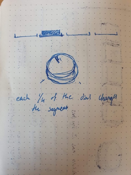
The potentiometer is going to be used to switch through segments, which in the final version will either switch between different shortcut profiles or be shortcuts in-and-of themselves.
The key of getting the segments working is the custom characters, created via an array of bytes,


When displayed on the LCD they look like this:

The byte arrays are converted into characters using lcd.createChar(i, n), where 'i' is the name that is used to call the character and 'n' is the name of the array of bytes.

This section of code goes in setup, and initialises the LCD and creates the custom characters.
The addition of a new component requires new code, this code being the 2 lines that gets a single value from the potentiometer. In the loop function, the value from the potentiometer is read using analogRead() and is assigned to the value variable. the value is the remapped to a new value, using the map() function. this takes the old highest and lowest point of a variable, and remaps the value between the new highest and lowest value, in the following format:
map(var, oldLow, oldHigh, newLow, newHigh);
below is how this has been used to reduce the wide range of values down to the 4 that will be used for the 4 segments of the potentiometer's shortcuts.

Code
#include <"LiquidCrystal.h">
//#include "layoutSettings.h" //old header file was going to be used to store the shortcut data
LiquidCrystal lcd(2, 3, 4, 5, 6, 7); //Parameters: (rs, enable, d4, d5, d6, d7)
//constants: const int potPin = A0; // input pin for dial
int value; //saves analogue value
//custom characters: byte cornerEmpty[] = { B00000, B00000, B00000, B10000, B10000, B10000, B10000, B11111 };
byte cornerFull[] = { B00111, B00111, B00111, B10111, B10111, B10111, B10000, B11111 };
byte midEmpty[] = { B00000, B00000, B00000, B00000, B00000, B00000, B00000, B11111 };
byte midFull[] = { B11111, B11111, B11111, B11111, B11111, B11111, B00000, B11111 };
void setup() {
//initialise display size lcd.begin(16, 2); //custom lcd chars lcd.createChar(1, cornerEmpty); lcd.createChar(2, cornerFull); lcd.createChar(3, midEmpty); lcd.createChar(4, midFull);
//contrast analogWrite(12, 30); // writes value 30 to pin D12
}
void loop() { value = analogRead(potPin); // potPin = analogue pin 0 value = map(value, 0, 1023, 0, 4);
if(value >=0 && value <1){
lcd.setCursor(0,1); lcd.write(2); lcd.write(4); lcd.write(4); lcd.write(4); lcd.write(1); lcd.write(3); lcd.write(3); lcd.write(3); lcd.write(1); lcd.write(3); lcd.write(3); lcd.write(3); lcd.write(1); lcd.write(3); lcd.write(3); lcd.write(3); }
else if(value >=1 && value <2){
lcd.setCursor(0,1); lcd.write(1); lcd.write(3); lcd.write(3); lcd.write(3); lcd.write(2); lcd.write(4); lcd.write(4); lcd.write(4); lcd.write(1); lcd.write(3); lcd.write(3); lcd.write(3); lcd.write(1); lcd.write(3); lcd.write(3); lcd.write(3); }
else if (value >= 2 && value < 3){
lcd.setCursor(0,1); lcd.write(1); lcd.write(3); lcd.write(3); lcd.write(3); lcd.write(1); lcd.write(3); lcd.write(3); lcd.write(3); lcd.write(2); lcd.write(4); lcd.write(4); lcd.write(4); lcd.write(1); lcd.write(3); lcd.write(3); lcd.write(3); }
else if (value >=3 && value <=4){
lcd.setCursor(0,1); lcd.write(1); lcd.write(3); lcd.write(3); lcd.write(3); lcd.write(1); lcd.write(3); lcd.write(3); lcd.write(3); lcd.write(1); lcd.write(3); lcd.write(3); lcd.write(3); lcd.write(2); lcd.write(4); lcd.write(4); lcd.write(4); }
}
0 notes
Text
Personal Project 3 - LCD Experiment
One of the main components of the project is the LCD display. This post will outline the process I used to acquire a functional LCD for this project. This is a preliminary test to the final test of the LCD, having the display being updated using a potentiometer.
The initial source I used was incredibly helpful. (https://howtomechatronics.com/tutorials/arduino/lcd-tutorial/)
It explains all of the basics of the LCD itself, and includes a helpful wiring diagram, shown below:

However, I deviated slightly from this diagram, as I did not use a potentiometer to control the contrast of the screen. Instead, I opted to set the display contrast in code, using the following line:


The image above shows the LCD functioning as expected, the text displayed is related to the functionality of the project. The wires seen going from the breadboard to the arduino are connected to VO, R/S, E and data pins 4 through 7. the rest of the pins are connected to the breadboard underneath the LCD, shown in the image below:

The blue marks on the breadboard are where the first and last pins on the LCD will be plugged in.
Code
#include // adds liquid crystal library
LiquidCrystal lcd(2, 3, 4, 5, 6, 7); //rs enable 4-7
const int potPin = A0;
int value; // save analogue value
void setup() { // put your setup code here, to run once: lcd.begin(16,2);// sets dimension of display analogWrite(1, 30); // sets contrast
lcd.createChar(1, cornerU); lcd.createChar(2, cornerF); lcd.createChar(3, centerU); lcd.createChar(4, centerF); }
void loop() { // put your main code here, to run repeatedly: lcd.setCursor(2,0); lcd.print("Profile: ASE"); }
0 notes
Text
Personal Project 2 - Improvements to Initial Idea
Over time, I have made some improvements to the initial idea presented in the previous post.
The main addition to the design is an LCD display, which is used to display the current shortcut profile, and the position of the potentiometer/dial, as shown in the diagram below.
This will be accomplished by making custom characters. They are made by creating a byte, and specifying the 8 bits inside it. The formatting is to make displaying the shape easier.

Below are some depictions showing the shapes in an easier to understand way. cornerU is on the left, and cornerF is on the right. The U and F stand for filled and unfilled, for a segments in the section mentioned above.


The pre-built keyboard will be swapped for mechanical key switches, as this is significantly easier to implement, and will require fewer workarounds to implement into a physical form factor.
I made a quick mockup of a 3d model while deciding on form factor, but this design has since changed to be a more ergonomic and aesthetically pleasing design. The binary switch has been cut from the design, as it was too limiting of a tool to include.

I will also be trying to develop an application using the Windows Forms solution in visual studio. With this, I hope to allow a potential user to customise each of the shortcuts on the dial and keys, along with multiple shortcut profiles for increased customisation. This will be expanded on in a future post.
Overall I would like final project to contain:
An LCD display
A potentiometer/dial
Keys with customisable shortcuts
An application that allows the user to customise the shortcuts and dial
0 notes
Text
Personal Project 1 - Initial Idea
For the personal project part of this module, I have decided on a practical artefact rather than an artistic one. My idea is to create a Human Interface Device (HID) that acts as an additional input stream on a PC, alongside a keyboard and mouse, with a dial that allows allows for more control in certain applications.
The initial design is based on the stream deck, a product by Elgato that is used by content creators and streamers to use macros and more niche keyboard shortcuts, improving their workflow. (Product: https://www.elgato.com/en/stream-deck)
My page of notes, detailing my initial idea:

For the keys, I would use a prebuilt USB shortcut keyboard. This was inspired by a Youtube creator who customised a shortcut keyboard to help with video editing. (Video: https://youtu.be/zMn6DPUre70)
The Key features are:
A potentiometer (the dial) to change between certain states, i.e. scenes in OBS, different brushes in Art Applications.
Binary switch, can be used to mute a microphone.
Keyboard shortcut keys, can be used for different shortcuts. Using a pre-built shortcut keyboard allows the reprogramming to be done using an external too.
An example of a USB shortcut keyboard:
0 notes
Text
Experiment 1 - Potentiometer/Servo Motor

An experiment using a potentiometer and servo motor, and how they can interact. The solution I have created in the image and video above uses the potentiometer dial to rotate the servo, visualised in the servo's arm rotating.
Using the servo Library in the Arduino IDE, I am able to create a Servo variable, which can store the pin information. This information is added using myServo.attach() in setup().

The const int potPin receives the input from the potentiometer, which is read repeatedly in the loop() function shown below. The value received is mapped from the original range to a range of 0 to 180, corresponding to the angle of movement that the servo will provide. The value is written to the servo, which will then move to the angle specified by the value variable.

Components Used:
1x Breadboard
1x Arduino Uno
1x Thumbwheel Potentiometer
1x Servo Motor (SM-S2309S)
0 notes
Photo

An infographic detailing the internal working of Nintendo’s Virtual Boy console.
It covers a brief history of the Virtual Boy console, outlining its features and describes its commercial shortcomings.
It shows an animated diagram of light reflecting off of a mirror, and the angle of the mirror changing to assist in the explanation of how the display technology works.
Additionally, it explains the origins of the technology, and briefly mentions how it came to be used in the Virtual Boy console.
---References---
[1] Rafferty, K. (1994). Super Mario takes leap into three dimensional space - ProQuest. [online] www.proquest.com. Available at: https://www.proquest.com/docview/187572329/D48A30915E5D417CPQ/1?accountid=8509 [Accessed 21 Mar. 2022].
[2] Semrad, E. (1995). Nintendo Stumbles with Virtual Boy Intro. Electronic Gaming Monthly, [online] Jan., p.6. Available at: https://retrocdn.net/images/8/8d/EGM_US_066.pdf [Accessed 21 Mar. 2022].
[3] 16BitReview (2015). How the Virtual Boy Display Works. [online] www.youtube.com. Available at: https://www.youtube.com/watch?v=IMd35q5PWFw&ab_channel=16BitReview [Accessed 21 Mar. 2022].
[4] [6] Edwards, B. (2015). Unraveling The Enigma Of Nintendo’s Virtual Boy, 20 Years Later. [online] Fast Company. Available at: https://www.fastcompany.com/3050016/unraveling-the-enigma-of-nintendos-virtual-boy-20-years-later [Accessed 21 Mar. 2022].
[5] Image Source: www.loper-os.org. (2012). Loper OS» For Your Eyes Only. [online] Available at: http://www.loper-os.org/?p=752 [Accessed 21 Mar. 2022].
1 note
·
View note