
Statistics
We looked inside some of the posts by brovolt-tech and here's what we found interesting.
Average Info
Notes Per Post
1
Likes Per Post
1
Reblog Per Post
0
Reply Per Post
0
Time Between Posts
18 days
Number of Posts By Type
Text
6
Last Seen Tumblr Blogs


Fun Fact
The Tumblr app for Google Glass was released on May 16, 2013.
Text
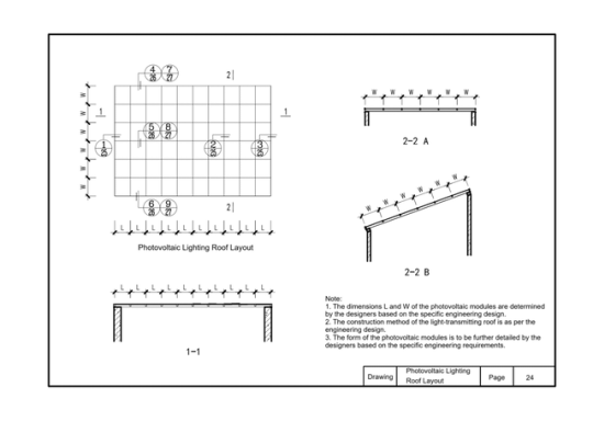
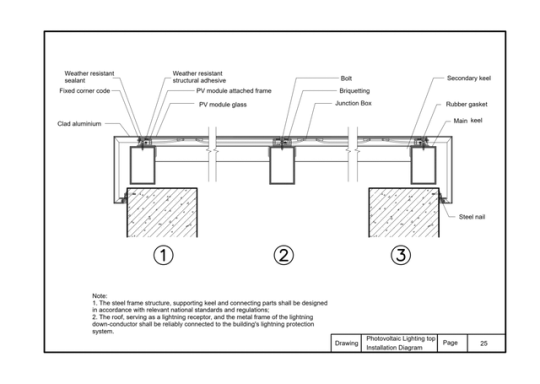
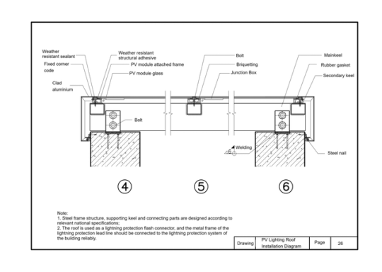
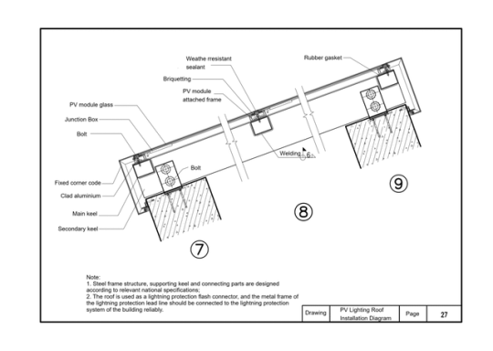
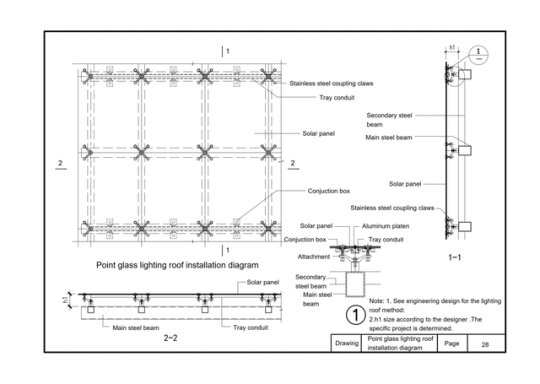
This atlas is derived from the guiding atlas for the design of building photovoltaic systems. It includes layout and installation diagrams for photovoltaic skylights, as well as installation diagrams for point-supported glass photovoltaic skylights. It briefly demonstrates how common components are installed, such as stainless steel connection claws, cable trays, secondary steel beams, photovoltaic modules, main steel beams, junction boxes, aluminum pressure plates, and point-supported accessories
0 notes
Text
Lithium ion batteries are widely used in energy storage and electric vehicle applications due to their safety, long cycle life, and stable performance. In this article, we will explore what lithium ion batteries are, how they work, their history, materials, manufacturing process, advantages and disadvantages, comparisons with other batteries, tips for choosing the best manufacturers, and their market demand.
What is a lithium-ion battery?
Lithium-ion Battery (Li-ion) is a rechargeable battery technology that uses the movement of Lithium ions to achieve energy storage and release. Lithium-ion batteries have the characteristics of high energy density, low self-discharge rate, no memory effect, long cycle life, etc., and are the most mainstream battery types for consumer electronics, electric vehicles, and energy storage systems.
1.1 Structural composition:
1.1.1 Positive electrode: the source of storage and release of lithium ions, which determines the voltage and energy density of the battery. Typically made from lithium iron phosphate (LiFePO₄), ternary lithium (NCM/NCA), or lithium manganate (LiMn2O4).
1.1.2 Negative electrode: Used to store lithium ions and release lithium ions when discharged. The main material is graphite (C), silicon carbon composite or lithium titanate (LTO).
1.1.3 Electrolyte: Acting as a transport medium for lithium ions, usually a lithium salt (such as lithium hexafluorophosphate LiPF₆) dissolved in an organic solvent
1.1.4 Diaphragm: Porous membrane material that allows lithium ions to pass through but prevents electrons from directly short-circuiting. Commonly used polyolefin (PE, PP) diaphragms.
How lithium-ion batteries work
2.How do lithium-ion batteries work
A lithium-ion battery is a rechargeable electrochemical device based on the principle of the conversion of electrical and chemical energy by the insertion and de-insertion of lithium ions (Li +) between positive and negative electrodes.
2.1. Charge process (Li + from positive → negative)
When the battery is charged, an external power supply applies a voltage push:
Lithium ions and electrons are released from the cathode material:
LiCoO2 →Li1-XCoO₂ + xLi+ +Xe-
Lithium ions (Li +) travel through the diaphragm through an electrolyte and migrate to the negative electrode.
Electrons (e⁻) are synchronized to the negative electrode by an external circuit. The negative electrode (such as graphite) is embedded in the lithium ion, forming a LiC₆
xLi++xe-+C6→ LixC6
At this time, the electrical energy is "stored in the negative electrode" to complete the charge
2.2 Discharge process (Li + from negative → positive)
When the battery discharge (power supply) , the direction of electrochemical reaction is reversed:
2.2.1 Lithium atoms in the negative electrode release lithium ions and electrons
2.2.2 Lithium ions return to the positive electrode through the electrolyte
2.2.3 Electrons flow along the outer circuit to the positive terminal, producing a current output
2.2.4 The positive electrode is re-embedded in lithium ion to complete energy release
materials for li-ion batteries
Development history of lithium-ion batteries
The development of lithium-ion batteries spans decades, covering multiple stages from theoretical proposals, technological breakthroughs to commercial applications and future technology exploration. The following is its key time nodes and stages of progressTheoretical foundation stage
3.1 1958: American physical chemist Gilbert N. Lewis first proposed the concept of "lithium battery".
Early 1970s: Dr. M.S. Whittingham develops the first lithium metal battery, using a TiS2 positive + lithium metal negative electrode, but it has serious safety problems (short circuit and explosive).
At this stage, although the energy density of lithium metal batteries is high, the safety hazards caused by lithium dendrites are difficult to overcome.
3.1. Lithium-ion battery principle established
1980: Professor John B. Goodenough invented lithium cobalt oxide (LiCoO₂) cathode material, voltage up to 4V, opening the era of high energy batteries.
1985: Dr. Akira Yoshino of Asahi Kasei, Japan, used graphite as a negative electrode material for the first time to develop a "metal-free lithium" lithium-ion battery prototype, greatly improving safety.
1986: Japan begins small-scale trial production of prototype lithium-ion batteries.
Yoshino, known as the "father of lithium-ion batteries," shared the 2019 Nobel Prize in Chemistry with Goodenough and Whittingham.
3.2. Commercialization takes off - SONY launches the world's first commercial lithium-ion battery
1991: Sony of Japan, in partnership with Asahi Kasei, launches the first commercial lithium-ion battery for cameras with high energy density, long life and superior safety.
In the late 1990s, laptops and mobile phones rapidly adopted lithium batteries, which led to an industry explosion.
This marks the official opening of the commercial era of lithium-ion batteries.
3.4. Material innovation and multiple applications
2001: Lithium iron phosphate (LiFePO₄) was developed as a new positive electrode material with improved safety for power and energy storage.
Since 2005: ternary material (NCM/NCA) has been put into industrialization to improve capacity and cycle performance.
2008: Tesla releases the first electric car Roadster, using lithium-ion cylinder battery (18650), electric vehicles into the mainstream vision.
A variety of new materials, cell structures (soft bag, cylinder, square) began to emerge.
3.3. Industry outbreak and energy storage revolution
After 2010: the surge in demand for electric vehicles and home energy storage systems led to the rapid development of the lithium battery market.
2013: BYD launches lithium iron phosphate electric bus.
2015: Tesla releases the Powerwall, a home energy storage system.
2018: Global lithium battery shipments exceeded 100GWh for the first time.
China, South Korea, Japan formed the "lithium battery three strong", CATL, BYD, LG, Samsung SDI and other rapid rise.
3.4. High energy, solid state, new system exploration
After 2020: New systems such as solid-state batteries, silicon-carbon anode, cobalt-free batteries, and sodium-ion batteries are continuously developed
2021: CATL releases sodium-ion battery samples.
2022: BYD launches "blade battery", using LFP to improve safety and space utilization.
2023: Global lithium ion battery shipments exceed 700GWh, and large-scale deployment of energy storage systems accelerates.
Since 2024, large-capacity energy storage power stations and household light storage systems have become the main market.
Development history of lithium-ion batteries
Detailed explanation of the main materials of lithium-ion batteries
4.1 Cathode material:
4.1.1 Lithium cobaltate LiCoO₂ : High energy density, often used in mobile phones and other devices
Ternary material NCM/NCA: the mainstream choice for electric vehicles, taking into account energy density and cost
Lithium Iron phosphate LiFePO₄ : Long life, high safety. Suitable for energy storage and household systems
Lithium manganate LiMn₂O₄ : Low cost, but relatively poor life and stability
4.1.2 Anode Material (Anode) :
Graphite: mainstream material, mature and stable
Silicon-carbon (Si-C) composites: Higher energy density, but large volume expansion, need to be controlled
Lithium titanate (LTO) : Extremely long cycle life, suitable for high rate applications
4.1.3 Electrolyte:
Composed of lithium salts (such as LiPF₆) and organic solvents, it conducts lithium ions
Solid-state electrolytes have been developed in recent years to improve safety
4.1.4 Separator:
Most of them are PP/PE microporous films with thermal closing function to prevent short circuit
main materials of lithium-ion batteries
4.2 Lithium iron phosphate battery(LiFePO4) outlook
Lithium iron phosphate battery (LFP) with its high safety, long cycle life and low cost, has become the absolute mainstream technology in the field of energy storage.
4.2.1 Main application scenarios in the energy storage field
Grid side energy storage (generation end + transmission and distribution end).
Peak and frequency modulation: LFP battery response speed up to millisecond, can replace traditional gas turbines, reduce grid fluctuation costs.
Smooth output of renewable energy: supporting photovoltaic/wind power projects to solve intermittency problems (such as 600MWh LFP energy storage power station in Qinghai Province, China).
Black start: provides support for the rapid restoration of power supply after grid failure (such as 182.5MW LFP energy storage system in California, USA).
User side energy storage (Industrial & Commercial + Household)
Peak-valley arbitrage: Industrial and commercial users take advantage of the price difference (such as China's peak-valley price difference exceeding 0.1USD /kWh), and the investment payback period is reduced to 5-7 years.
Standby power supply: Data centers, hospitals and other sensitive scenarios, LFP cycle life of more than 6000 times, reduce the replacement frequency.
Household light storage systems: LFP penetration in the European household storage market increases from 20% in 2020 to 60% in 2023 (Tesla Powerwall 3 fully switches LFP).
4.3 New Application Scenarios
4.3.1 Electric vehicle charging station energy storage: buffer the grid load and support the high-voltage demand of fast charging pile (such as the "optical storage and charging" integrated station cooperated by CATL and Star Charging).
4.3.2 Microgrid and off-grid power supply: Energy independence in remote areas/islands (such as the 50MWh LFP off-grid energy storage project in Tanzania, Africa).
4.4. Core advantages of LFP leading energy storage market
4.4.1 Economical rolling
Kilowatt-hour cost (LCOS) : LFP energy storage system LCOS has been reduced to 0.02-0.04 USD/time, lower than ternary batteries (0.0.045-0.0.06 USD/time) and lead-acid batteries (0.085 USD/time).
Cycle life: 6000 cycles (80% capacity retention rate) vs 3000 cycles for ternary batteries, 500 cycles for lead-acid batteries.
4.4.2 Outstanding Security Performance
Thermal stability: LFP thermal runaway temperature > 500℃, much higher than ternary battery (200℃), through acupuncture, overcharge and other safety tests.
Cobalt-free nickel controversy: circumventing the resource monopoly of cobalt-nickel in ternary materials (Congo cobalt mines account for 70%) and moral hazard (child labor).
Meet the requirements of the energy storage scenario
Low self-discharge rate: monthly self-discharge < 2%, suitable for long-term idle backup power supply scenarios.
Wide temperature range: Stable operation from -30 ° C to 60 ° C through electrolyte formulation optimization (e.g. adding LiFSI).
4.5. Global market pattern and competitive dynamics
Market size and growth
China: New energy storage installed capacity of 21.5GW in 2023, LFP accounted for more than 95%b), 2025 planning target of 60GW.
Europe and the United States: The US IRA bill promotes the increase of energy storage installed capacity by 200% in 2023, and the proportion of LFP rises from 30% to 65%; The LFP penetration rate of the European household storage market exceeds 70%.
Emerging markets: energy storage demand in Southeast Asia and Africa is increasing by 50% annually, and Chinese manufacturers dominate exports.
PV Energy storage charging station
Production process of lithium-ion batteries
Lithium battery manufacturing process is strict, mainly including the following five steps:
Electrode preparation
Mix: Active material + binder + conductive agent
Coating: The paste is evenly applied to the aluminum/copper foil
Drying: Remove solvent
Compaction: Increase the density and consistency of the pole plate by rolling
Battery assembly
Pole cutting and lamination/winding: The core structure is formed according to the cell type
Diaphragm insertion: prevents short circuit
Injection electrolyte
Package sealing: Use aluminum shell, soft package or cylindrical package form
Formation and separation
Formation: First charge and discharge to form a stable SEI film
Capacitance: Test the capacity, voltage, internal resistance of each cell, and grade sorting
Module/battery pack assembly
Parallel/series configuration: Modules are assembled according to the system voltage and current requirements
Integrated BMS system: Monitor temperature, voltage and current for safe operation
Final inspection and delivery
Quality test: including capacity, life, drop, temperature cycle, etc
How Lithium-ion Batteries are Produced
6.Advantages and disadvantages of lithium-ion batteries
Advantages:
1 High energy density: light size, strong power
2 Long life: cycle life can reach more than 2000~6000 times
Low self-discharge rate: long-term storage is not easy to lose power
No memory effect: It can be used on demand
Diversified packaging: suitable for different equipment requirements (soft package, cylinder, square)
Cons:
High cost: The price of high-quality lithium raw materials fluctuates greatly
Temperature sensitive: Performance declines under high temperature or extremely cold conditions
Risk of thermal runaway: Improper design /BMS may cause overheating or fire
Strong resource dependence: It is dependent on lithium, cobalt, nickel and other resources
Comparison of Lithium-ion Batteries vs. Other Batteries in Energy Storage Systems
Tips for choosing a quality lithium battery manufacturer 7.1 Here are the tips for choosing a good manufacturer
1.Whether customized solutions are supported
2.Have a reliable BMS and EMS control system
3.Whether it has passed authoritative certification (such as UN38.3, CE, IEC62619)
4.Whether there are actual project cases and user word-of-mouth
5.Warranty period and after-sales response speed
6.Meet the application requirements of the energy storage scenario (temperature control system, fire protection system, communication protocol compatibility)
7.2 .Why choose Brovolt energy storage system and lithium ion batteries?
Brovolt is committed to providing safe, intelligent and efficient energy storage solutions to customers around the world. With its leading technology and high-quality services, it has won wide recognition from customers. Here are six reasons why we stand out:
7.1. Support customized solutions
Brovolt provides a full set of energy storage system customization services, which can tailor battery capacity, voltage level, communication protocol, cabinet structure and other parameters according to the specific needs of users, and adapt to various application scenarios such as residential, industrial and commercial, off-grid, microgrid, etc.
7.2. Equipped with advanced BMS and EMS control systems
The system has built-in intelligent battery management system (BMS) and energy management system (EMS) to achieve:
Real-time monitoring and fault warning
Remote control and data cloud platform docking
Energy optimization scheduling to improve system operation efficiency and life
7.3. Passed multiple international authoritative certifications
Brovolt energy storage products have passed the following international standard certifications to ensure global compliance and reliability of products:
UN38.3: Transportation safety certification
CE: EU market access standard
IEC62619: International standard for lithium-ion battery safety
7.4. Real project cases + customer reputation
Brovolt products have been widely used in energy storage projects in Nigeria, Kenya, South Africa and other places, covering home power backup, industrial and commercial peak shaving and valley filling, grid-side energy storage, etc., with good customer feedback and testable project landing capabilities.
7.5. Long warranty period and fast after-sales response
Standard warranty is 5 years, which can be extended to 10 years
Provide a response mechanism within 24 hours, remote diagnosis and technical support
7.6. Fully meet the needs of energy storage application scenarios
Built-in temperature control system (air conditioning/air cooling/liquid cooling) to maintain system stability
Integrated fire protection system (aerosol/smoke detection) to ensure safety
Compatible with mainstream brand inverters, supporting Modbus, RS485, CAN and other protocols
We not only deliver batteries, but also deliver a complete, safe and reliable energy system.Choose Brovolt to light up the green future of every family and enterprise
11122
8.Future trends and market demand of lithium-ion batteries
Lithium battery market demand will continue to grow rapidly, driven by:
Renewable energy storage system
Electrification of electric vehicles, buses, two-wheelers, etc
Universal electricity demand in developing countries (e.g. Africa)
Home Energy Independent system (PV + energy storage)
New technologies (solid state, sodium ion, electrolyte improvement) continue to advance
According to market forecasts, by 2030, the global annual production capacity of lithium batteries will exceed 5TWh, and energy storage systems will become one of the fastest growing application sectors.
Conclusion
Lithium-ion batteries are not only the cornerstone of modern science and technology, but also an important driving force for energy transformation. With technological progress and mass production, it will become safer, more efficient and more economical. For enterprises and individual users, choosing mature lithium battery system manufacturers and solutions will be a key step towards a green energy future.
0 notes
Text
I.Inverter selection basis
1.1. "Shell Protection Level (IP code)" GB 4208
1.2. "Photovoltaic power generation grid-connected inverter technical requirements" GB/T 37408
1.3. "Photovoltaic power station access to power system technical regulations" GB/T 19964
1.4. "Electrical and electronic products basic environmental test procedures" GB/T2423
1.5. "Grid-connected photovoltaic Inverter Technical conditions" CNCA/CTS 0004
1.6. "Photovoltaic grid-connected system inverter anti-island test method" IEC 62116
1.7. Safety of Inverter for Photovoltaic power generation IEC 62109-1/2
1.8. "Photovoltaic grid-connected inverter Technical specification" NB/T32004
2. Design parameters
2.1The inverter is the core equipment and technical key of the photovoltaic system, converting the direct current emitted by the battery array into AC power that is easy to be transmitted over a long distance after voltage boost. The grid-connected inverter can adjust the frequency, voltage, current, phase, active power and reactive power of the AC output side of the inverter according to the power characteristics of the connecting point.
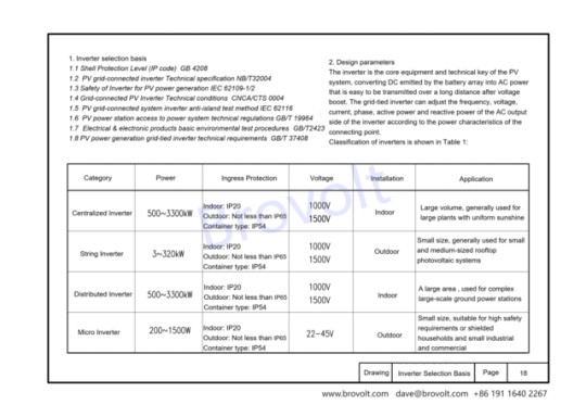
Classification of inverters is shown in Table 1:
2.2 Centralized inverter
The centralized inverter summarizes the DC generated by the photovoltaic module into a larger DC power and then inverts it. The power of this type of inverter is relatively large, and the single capacity is generally above 500KW. It has the advantages of large output power, mature technology, high power quality and low cost, but at the same time it has the disadvantage of insufficient MPPT tracking accuracy. It will affect the efficiency and electrical capacity of the entire photovoltaic power station when it encounters cloudy, shaded or a single series failure, and requires a dedicated room for ventilation and heat dissipation, so the variety is usually used in centralized large-scale photovoltaic power stations with uniform light
2.3 String inverter
Several groups of photovoltaic series for a separate maximum power peak tracking, and then after the inverter into the AC power grid, this type of inverter power is relatively small, single power is generally below 100KW, with the technical progress and cost reduction and efficiency demand is becoming increasingly prominent, the power gradually increased to 136KW, 175KW and other high-power products. It has the advantages of large number of MPPT, flexible component configuration, easy installation, high tracking accuracy, high power generation, fast operation and maintenance, but also has the disadvantages of slightly poor power generation quality and high cost, mainly used in small-scale household distributed power generation, small and medium-sized industrial and commercial rooftop power stations.
2.4 Distributed inverter
Distributed inverter realizes multi-channel MPPT optimization function by pre-controlling multiple MPPT optimizers, and adopts centralized inverter inverter after convergence. This type of inverter combines the advantages of "centralized inverter" and "decentralized MPPT tracking" of large-scale centralized photovoltaic inverters to achieve low cost and high reliability of centralized inverters and high power generation of serial inverters. According to the Sobi photovoltaic network, the distributed type is 2%-5% higher than the centralized power generation, and has better power quality, grid adaptability and lower system investment costs than the string inverters
2.5 Micro inverter
Micro inverter for each photovoltaic module for a separate maximum power peak tracking, and then through the new energy power generation after the inverter into the AC grid, this type of inverter single capacity is generally less than KW, with each component independent maximum power tracking control, in the case of shading or component performance differences to improve the overall efficiency, to minimize safety risks and other advantages. Its disadvantage is high price, more difficult to maintain after failure, more suitable for smaller projects.
3. Inverter selection requirements
3.1 The requirements of the State Grid for distributed photovoltaic power stations are as follows: 220V can be accessed below 8kW; 8kW~ 400kW can be connected to 380V; 400kW~6MW can be connected to 10kV. According to the characteristics of the inverter, the selection of photovoltaic power plant inverter is shown in the figure:
3.2 The roof of 10kV project is generally a large roof, a single roof arrangement of the roof capacity of up to MW, a single inverter under the same MPPT circuit of the photovoltaic module inclination, orientation and shadow occlusion is consistent, it is recommended to choose a centralized inverter.
3.3 The design of the roof photovoltaic power station is relatively complex, affected by the roof structure, size, layout, materials, bearing and shadow occlusion and other factors, need to maximize the benefits through the photovoltaic module laying and inverter selection planning. The layout of photovoltaic modules on the roof is mostly blocked or the orientation is inconsistent, in order to simplify the design, it is recommended to choose a series inverter.
3.4 The roof of the plant is mostly color steel roof, bearing limited, can not install a series of inverters, and need to meet the daily maintenance, does not affect the normal production and operation requirements, can choose a centralized inverter.
4.Inverter installation requirements
4.1. Environmental requirements
4.1.1 There should be no flammable and explosive materials in the installation environment; 1.2 Should not be installed in places accessible to children:
4.1.3 Temperature and humidity should meet the following requirements:
Maximum ambient temperature :+60℃; Minimum ambient temperature :-30℃; Maximum relative humidity :100%(non-condensing)
4.1.4 To avoid direct sunlight, direct rain and snow, extend the service life of the inverter, outdoor installation of the inverter should be set in a position that can shade the sun and rain:
4.1.5 To ensure smooth ventilation and heat dissipation of the inverter, it is appropriate to install the inverter in a ventilated environment :1.6 for 10kV series inverters or centralized inverters, the inverter should be installed in a position greater than 30m away from third-party wireless communication facilities or residential.
4.2 Installation carrier requirements
4.2.1 The installation carrier should not be flammable material:
4.2.2 The maximum bearing capacity of the carrier is >4 times the weight of the inverter.
3.Angle
4.3.1 Vertical installation or backward tilt installation of inverters (the required Angle to the ground >10°), should not be installed forward or upside down:
4.3.2 The installation height of the inverter meets the requirements of the turning radius of the cable and is convenient for personnel to operate.
4.Protectionfunctionrequirements
(1) DC input side overvoltage protection
(2) AC output side overvoltage/undervoltage protection
(3) AC overpass/underfrequency protection:
(4) DC input or AC output polarity misconnection protection
(5) AC output side phase protection
(6) DC input overload protection
(7) Output short-circuit protection:
(8) DC side back discharge protection
(9) Anti-island effect protection:
(10) The function of restoring the grid connection when the frequency voltage on the AC side returns to normal:
(11) High temperature cooling protection function:
(12) Lightning protection.
5, inverter DC input voltage requirements
(1) Under the extreme low temperature operating conditions of the photovoltaic module, the open circuit voltage of the photovoltaic series DC side is < the maximum DC input voltage of the inverter:
(2) Under extreme low temperature working conditions, the working voltage of the DC side of the PV module is < the maximum voltage of the inverter Mppt;
(3) Under the extreme high temperature operating conditions, the working voltage of the PV series DC side is > the minimum voltage of the inverter Mppt.
1.5 To ensure smooth ventilation and heat dissipation of the inverter, it is appropriate to install the inverter in a ventilated environment :1.6 for 10kV series inverters or centralized inverters, the inverter should be installed in a position greater than 30m away from third-party wireless communication facilities or residential.
2 Installation carrier requirements
2.1 The installation carrier should not be flammable material:
2.2 The maximum bearing capacity of the carrier is >4 times the weight of the inverter. The Angle is required
3.1 Vertical installation or backward tilt installation of inverters (the required Angle to the ground >10°), should not be installed forward or upside down:
3.2 The installation height of the inverter meets the requirements of the turning radius of the cable and is convenient for personnel to operate. 4
(1) DC input side overvoltage protection (2) AC output side overvoltage/undervoltage protection
(3) AC overpass/underfrequency protection:
(4) DC input or AC output polarity misconnection protection
(5) AC output side phase protection
(6) DC input overload protection
(7) Output short-circuit protection:
(8) DC side back discharge protection
(9) Anti-island effect protection:
(10) The function of restoring the grid connection when the frequency voltage on the AC side returns to normal:
(11) High temperature cooling protection function:
(12) Lightning protection.
4.Inverter DC input voltage requirements
(1) Under the extreme low temperature operating conditions of the photovoltaic module, the open circuit voltage of the photovoltaic series DC side is < the maximum DC input voltage of the inverter:
(2) Under extreme low temperature working conditions, the working voltage of the DC side of the PV module is < the maximum voltage of the inverter Mppt;
(3) Under the extreme high temperature operating conditions, the working voltage of the PV series DC side is > the minimum voltage of the inverter Mppt.
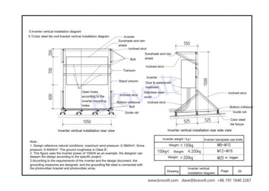
5..lnverter vertical installation diagram
5.1. This figure is suitable for vertical installation of inverters and installation of color steel tile roof brackets.
5.2. Sun shield/brace/beam/column/stainless steel shield/bottom beam/guide rail/color steel tile fixture
5.2.1 Inverter mounting holes and bolt specifications
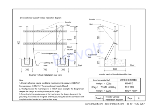
Inverter weight <100kg Bolt M8~M10
100kg ≤ Inverter weight ≤ 200kg Bolt M12 to M16
Inverter weight >200kg M20 and above
5.3. Design reference parameters
5.3.1 Maximum wind pressure: 0.38kN/m²; Maximum snow pressure: 0.40kN/m²;
Ground roughness: Class B
5.3.2 The inverter power example is 100kW, the specific project can be further designed according to the actual situation.
Grounding measures should be taken according to the requirements of the design document, and the grounding flat steel should be connected with the photovoltaic bracket, inverter and photovoltaic array.
5.4. Other installation requirements
5.4.1 The inverter back plate must be perforated according to the installation hole positions, and secured by bolts of the corresponding specifications.
5.4.2 After the column and bottom beam are installed, waterproof and glue should be applied to ensure long-term safety.
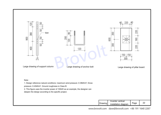
2. .Concreteroofsupportverticalinstallationdiagram
2.1. This drawing is suitable for vertical installation of inverters and vertical installation of concrete roof supports.
2.2. Mounting accessories are bolts/expansion bolts/purlins/ground copper wire/ground flat steel/post/anchor bolt
2.3.1 Design reference natural conditions: maximum wind pressure: 0.38kN/㎡; Snow pressure: 0.40kN/㎡; The ground roughness is class B.
2.3.2. This drawing uses the inverter power of 100kW as an example, and designers can deepen the design according to specific projects;
2.3.3. Design the grounding measures according to the requirements of the inverter and the design document, and the grounding flat steel is connected with the photovoltaic bracket and photovoltaic array

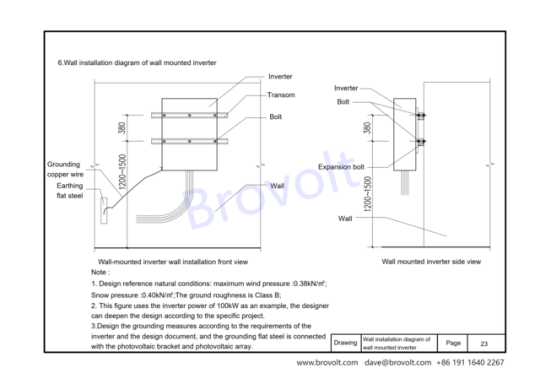
6. Wall installation diagram of wall-mounted inverter
6.1. This drawing is suitable for wall installation of inverters
6.2. Installation accessories include bolts, expansion bolts, beams, ground copper wires, and ground flat steel
6.3.1 Design reference natural conditions: maximum wind pressure: 0.38kN/㎡; Snow pressure: 0.40kN/㎡; The ground roughness is class B.
6.3.2. This drawing uses the inverter power of 100kW as an example, and designers can deepen the design according to specific projects;
6.3.3. Design the grounding measures according to the requirements of the inverter and the design document, and the grounding flat steel is connected with the photovoltaic bracket and photovoltaic array
0 notes
Text
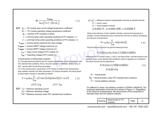
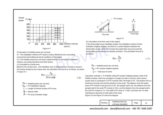
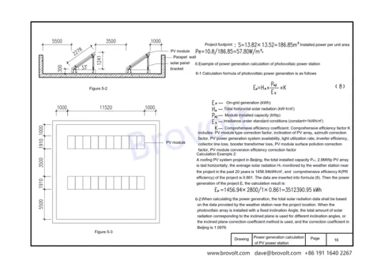
How to calculate actual power of PV array and whole PV system power? Please check blow link to learn more. A 10.8kWp roofing PV project in Beijing adopts a total of 20540Wp modules, which are arranged in a single row with 2 columns. Each columnsquare array is composed of 10 PV modules with a tilt Angle of 33°. The project roof is areinforced concrete roof and the direction is due south. The distance from the lowestpoint of PV module to the ground is 0.3m, the parapet wall is 2m, the distance from theparapet wall to the south PV module is 5.5m, and the distance from the parapet wall tothe north PV module is 1m. The width of PV array is 11.52m, and there are 1m widemaintenance channels on both sides of the array. #PVmodeule #solarpanel #renewableenergy
0 notes
Text
What can you do when the battery catches fire? All we can do is watch it burn up. This is a poor quality product. BroVolt insists on high quality products and refuses to use inferior raw materials.
0 notes