
ARCH 4050/6306 University of North Carolina at Charlotte / Urban Synergetics Lab
Don't wanna be here? Send us removal request.
Statistics
We looked inside some of the posts by connective-environments-fall2019 and here's what we found interesting.
Average Info
Notes Per Post
2
Likes Per Post
2
Reblog Per Post
0
Reply Per Post
0
Time Between Posts
1 day
Number of Posts By Type
Text
17
Last Seen Tumblr Blogs


Fun Fact
Tumblr Inc. is funded by 13 investors.
Text
Vocal Visuals: audio and visual telepresence
Eliot Ball and Ricky Young
We bring to you our finding and studies of how a pair of people interact through a point in an axis controlled by the sounds they make.
And talk about the final advances that brought us to a point where we could test this project.
Stereo Amplification and Dual Screen Routing
The stereo amplifier that we purchased (the LEPY 2020A) was key to the success of the oscilloscope system. Prior to purchasing an amplifier, the waveform was so small the display appeared as simply a quivering line on each axis. The amplifier increased the amplitude of the signal enough to provide each axis with a waveform capable of taking up the entire screen. In addition to this, the amplifier came with a built in voltage transformer. It seems as though this transformer as provided the coil within the television with the proper amount of signal, therefore solving the problem that plagued many of our previous iterations. Because the television was being fed the proper amount of voltage, the system didn’t fail or automatically should down.
With the issue of the television and waveform displays solved, we moved on to the problem of how to make this installation into a dual screen set up. We took advantage of some home studio equipment we had available. Using an audio interface (a Focusrite Scarlett 18i20), we were capable of developing a series of routing paths that would split input signals, meaning each microphone could be sent to multiple sets up televisions at once (up to 8 in fact.) We then purchased a specialty microphone cable that converted a standard XLR jack into a stereo RCA output. Each stereo amplifier requires a stereo RCA input, so this cable was paramount in transferring the standard microphone jack into something capable of being received by the amplifiers.
Within the audio interface’s software, we assigned these specialty microphone cable as outputs 1+2, and a monitor speaker for each TV as outputs 3+4. We then instructed each microphone signal to be sent to their corresponding specialty cables, as well as sending each microphone to the speakers. Because the specialty cable resulted in a stereo RCA jack, we then routed ONE of each stereo pair to either amplifier. The resultant signal path gave each television a display of both microphone inputs.

a diagram showing the wire we used to split the XLR audio signal from the microphone into left and right RCA signals.

diagram of the full system with pictures of each element
User Studies and Results
With all systems solved and ready for installation, we ran a series of user studies in order to observe how participants would interact with the interface. We specifically wanted to see how a diluted sense of each other’s presence might affect a user’s interaction with the opposite person. Would such a scenario enhance two strangers attachment do one another? What might occur when two people familiar with one another? We wanted to see what trends we could observe based upon the relationships of the two people, and also see how much cooperation was fostering through interacting with the interface.
In addition to letting the two participants hear both of their voices while speaking, we also engaged in an alternative version of the experiment that prohibited the users from hearing one another. This involving cutting the microphone input to the speaker, pumping white noise to each user, and giving each person a pair of ear plugs. We observed the differences between a purely visual stimulus and one with both audio and visual cues.
While the studies were occurring we also recorded each interaction on both microphones and with a video camera on each participant. With the recordings handy, we can pump the original audio back through the interface, effectively creating a simulation of their initial dialogue.
After each pair finished their session, we gave them each a questionnaire in order to gauge their reaction to the experiment. The questions focused on their own feelings during their experiment, their engagement and connection to their partner, and also if they felt the interface enabled or inhibited a meaningful interaction.
Discussion of Results
After observing and recording the user studies, we began to notice several trends develop within the experiments. Many reacted positively to their partners role in the interaction. Each group had a different dynamic, but in general pairs (who often did not know each other prior to the installation) would sing together, hum together, or make wacky noises together. They observed the visual output of their voices, augmenting the sounds they made to play with the shapes that appeared on scream. Some would coordinate efforts, each producing a different noise to facilitate a unique shape. Others attempted to match notes in order to make a “perfect circle�� or to at least make the waveform stand still for a brief moment.
There was a minority of participants who seemed to feel mildly uncomfortable with the experience, choosing to talk in short bursts and observe their individual axes move horizontally or vertically, never fully giving themselves to the interface. Yet it should be noted that there was never any disinterest. Those who felt uneasy engaging with their partner still interacted with the interface and expressed enjoyment in the outcome. Still others began to engage before laughing too hard to continue, not an ideal but still very satisfying outcome.
In general, observing one's partner through the abstracted lens of diluted physical presence, meaning a distillation of an individual into merely one or two perceptible variables, seems to have an effect on the user's inhibitions and sense of humility. In a way the installation acting as an ice-breaker of sorts. Here are some quotes from the questionnaire that reinforce that notion:
What effect did the interface have on two strangers interacting with one another?
“I could communicate with someone that I didn’t know through something that I wasn’t familiar with, but it was actually working.”
“It was just an instant moment of collaboration.”
“I feel as if I went on a blind date spontaneously, the TV allows for a level of intimacy that you might not have ever expected with the person you’re doing the experiment with.”
“I didn’t know my partner, but the oscilloscope allowed us to have fun together and be silly in a way that we wouldn’t have been able to without the oscilloscope.”
How did the interface contribute to the interaction with the other user?
“Well, it was the limitation of interaction that really defined the connection.”
“Took away the human element. It felt like the future of communication.”
“It was kind of like a battle to see who could get the longest or highest line between the two of us. But it was cool to see the mix of the same pitch and volume.”
“It made me question his intentions or emotions.”
“Technology typically doesn’t require more than one person to activate, so the act of collaboration makes more a dependence we tend not to expect/encounter.”
Further studies will continue using these oscilloscopes. More intense scrutiny regarding participants relationships to one another will further develop and uncover trends of human interaction and meaningful connection. Though in general we are very happy with the methods in which people cooperated and created together, forming small visual artifacts that are quite literally a composition of their combined efforts. More work to come, stay tuned.
0 notes
Text
FINAL : ART-APPARATUS
Telepresence Art : A Posthuman Sentiment of ‘Being There’
Project Conclusions // Thoughts // Final Prototype
( Christopher Meza + Arghavan Ebrahimi )
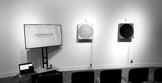
Art-Apparatus // Telepresence Art // Installation.

Illustration (1) : This illustration diagrams two art-apparatus, in remote locations.
INTRODUCTION :
This research project opens the discussion to the homogenization of telepresence, robotics, and new interpretations of remote human-art interfaces and interactions. “Telepresence art”, in this project, can be understood through the broader context of “electronic interactive art.” [Telepresence art] Through research, in this context, we have merged the language of electronic interactive art with the sensation of being elsewhere created through telepresence. This constructed approach to “interactive remote control,” opens the post-human dialogue of what is created and left remnant once a user moves on. Similarly, scientific telepresence research has focused on tele-robotics and teleoperation [Telepresence art on the internet]. This posthuman connotation allows the manipulation of presence-based parameters that can now be used to directly connect art to its viewers in remote locations. Stemming from this concept two minimalist art-apparatus, that could react to the presence of users, were developed. With this approach, the art-apparatus, and art in general, is no longer a locally responsive static object, rather it would be a dynamic alive entity.

Illustration (2) : This illustration diagrams the art-apparatus mounted on the wall, giving reference to proportion, and approximate range of response / interaction.
COMPUTER BASED ART :
In computer-based interactive art, the artwork comes into being through a process of exchange or dialogue between an active audience and a dynamic art-system. [ 24 ] This project creates a similar process through which the user engages in a art-apparatus. However, rather than creating a dialogue that conveys a message, or creates a projected instant result, the dialogue is the creation of a reconfigured art display, in a remote location. Additionally, to further develop the dialogue between two remotely located art-apparatus, the user intervention only modifies the art-apparatus located remotely; not the locally present art apparatus. Hypothetically, if there were two users. One at either end; the two art-apparatus’s would remain in a constant state of reconfiguration.

Illustration (3) : This illustration diagrams the basic structure of the art-apparatus.
PRESENCE :
The sense of presence emerges from basic psychological processes related to human action and its organization to the directed with intention (or interaction) with the environment. In a curated environment, such as an installation, the mediation of the interface becomes the center of action. [20] This crucial moment in which the attention changes from the presence of the user being perceived locally, allows the project to gestate the curation of a new artistic representation remotely.

Illustration (4) : This illustration diagrams the basic structure of the art-apparatus. Oriented as it would be mounted on a wall.
PROGRAMMING :
As technology and art merges, artists have found ways to work with computers and visual interaction in order to create artworks in complex and varied formats and environments. [ 13 ] With interactive remote-control art, we opted to create a new form of interaction. For the art-apparatus to communicate with another remotely located apparatus, we used the Client/ Server technology to connect two remote environments together. The electronic programmable components we used to program such a system included Arduino modules as part of the main interface.
youtube
Video (1) : During the programming phase of the project, we conducted several tests in order to validate the use of proximity sensors and servo motors. The video above shows data being collected and communicated through a server; eventually connecting it to the servo motor and outputting a distance correlated movement.
To implement the real-time communication between the client application and server, we used Socket.IO library in the code which programs the Arduino IDE. Socket.IO is the module of Node.js, and is designed based on web socket protocol [ 10 ]. The ESP32 collects data from the sensors and based on the input, it triggers the (remote)servo motor through an internet based server using websockets. The servo motor then rotates the top circular surface. As each proximity sensor is triggered, depending on the proximity of people on the other side, the servo motor will respond by moving with a change in degrees that correlates to the distance between users and the art-apparatus.
youtube
Video (2) : This video shows further testing of the sensors. The constant troubleshooting was necessary in order to properly calibrate the sensors.

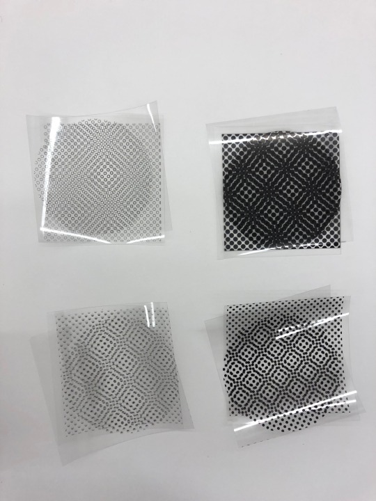
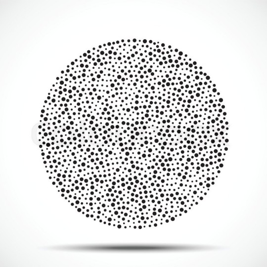
Image (1) : This illustration diagrams some of the possible pattern variations.
ART LOGIC :
To better understand the intersection of art and technology, and the justification for art, the theoretical work or Paul Virilio distinguishes three kinds of logic of images in congruence to a clear historical development. The first is the formal logic achieved in the eighteenth century with painting, engraving and architecture. Through this representation the “composition” has relevance, muting the flow of time contrasting from this instance where time is absolute. The second logic is revealed as the photography and cinematography in the nineteenth century; images corresponding to events in the past. In this instance, time is differentiated. The third, is paradoxical logic developed through the intervention of computers and satellites. For example, images are created in real time giving priority to speed over space changing the output of imagery from something given to something that has been constructed. Virilio also says that “reality has never been given, it has been acquired or generated.” [11,12,17] It is through this lens of generative imagery over space and time that the use of patterns to develop “art” truly homogenizes interactive-remote art and telepresence art.

Image (2) : Close up view of a possible pattern variation.
PATTERN LOGIC :
In mathematics, physics, and art, moiré patterns or moiré fringes are large-scale interference patterns that can be produced when an opaque ruled pattern with transparent gaps is overlaid on another similar pattern[ 19 ]. We applied the capability of these patterns to have several variations on the canvas. We put two layers of the same pattern on the acrylic sheets. The front sheet rotates with the servo motor and the rotation of the sheet creates a variation in the pattern every 10 degrees, creating a new pattern and creating a sense of motion.

Image (3) : Close up view of a possible pattern variation.
IMAGERY (PATTERN) INTERACTION :
The user interaction with these art-apparatus, in visual ways, allows the dynamic reconfigurations of the imagery to develop into new visual explorations of form and possibility. [16] Beyond the imagery and semiotics, a posthuman theory approach raises the question of technology’s ability to express the remnants of imagery developed through presence-based experience. [14] When there isn’t someone on the other end, we are left with the remnants of a process that someone developed with their presence. Witnessing the relational remnants of the artist, art, and the subject brings forth a new means of connection. [16] This allows the audience to experience the presence of another user (or witness) – the user or artist – this allows the current user to imagine him- or herself in the remote location of the witness [4,5].
youtube
Video (3) : This close up view of one of the art-apparatus shows the pattern changes when the kinetic and static surfaces overlap.
youtube
Video (4) : This close up view of one of the art-apparatus shows the pattern changes when he kinetic and static surfaces overlap and change their position in place.
ASSEMBLY : The apparatus itself, is composed of a series of layers, fastened together with four bolts, one at each corner.
● Layer 1 : Plywood Base – Structural function,frame for motor and electrical components. Painted white to hide the imperfections of the plywood. ● Layer 2 : White surface sheet –visually conceals the servo motor ● Layer 3 : Static acrylic surface; populated with black dots (circle outlines, on second apparatus) in an offset column pattern. ● Layer 4 : Kinetic acrylic surface; populated with black dots (circle outlines, on second apparatus) in an offset column pattern.

Illustration (5) : This illustration diagrams the order of assembly for the art-apparatus.
The assembly is a result of both aesthetic design and function. The plywood board has a perforation offset from the center that allows the wires of the servo motor to connect to the other electrical components at a shorter length. Both acrylic surfaces also have perforations that allow the arm of the servo motor to attach and rotate without generating friction. Furthermore, the bolts also work as a means of separating the apparatus from the wall. This creates a gap that allows access to the electrical components in the back of the apparatus. Additionally, the Proximity sensor and the electrical modules are arranged in such a way that each of them can be promptly accessed in case of an error or malfunction.
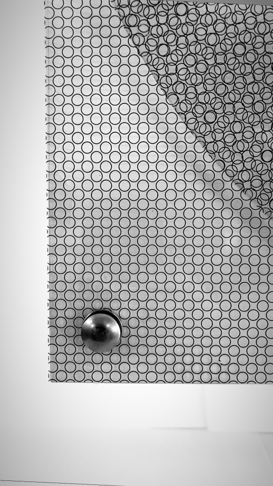
Image (4) : Corner condition, showing the aesthetic relationship between the bolt and the circles.
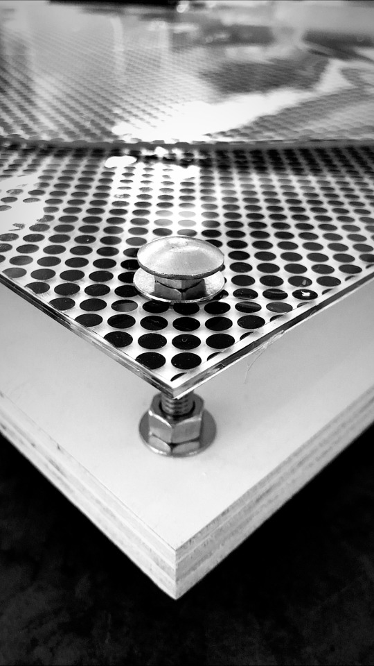
Image (5) : Corner condition, showing how the bolt assembly addresses the wood frame.

Image (6) : Sensory condition, image showing how the sensor is mounted to the wooden frame.
youtube
Video (5) : This video shows the attachment detail of the proximity sensor. Using and fabricating detail modules that facilitated the quick attachment or release of components was key in encapsulating all the electrical parts in once art-apparatus.
OBJECT LOGIC : Like television, radio, and other communication devices, in order to connect people, the art-apparatus, works through real time. However, different from those devices, the art apparatus is not used to communicate a coded or encrypted message, yet. [12]Both in a physical sense and a technological sense, communication with digital devices happens in places, on places, and across places. The newly constructed interactive-remote art logic only adds another layer to the multifaceted entanglement of communication and opens the possibilities to what a network of these objects (art-apparatus) can conceive. [1]. The patterns and structure of the object, additionally, can then be referenced back to a posthuman logic. When the materiality of the witness, in this case the user or artist is non-present at one end, the art still has remnants that have an impact beyond the semiotic. In this project, the apparatus challenges the idea thatpresence is crucial to telepresence art. Understanding the role of presence in temporal and spatial terms furthers the discussion of posthumanism. The interaction with the art-apparatus, in terms of imagery as well as where the device is activated through interactive presence. [2,3,25,27]

Illustration (6) : This illustration depicts the possible user(witness) interaction with the art-apparatus.
POSTHUMANISM :
The power of the posthuman in journalism, raises questions that can also be asked in telepresence art; What does it mean to be there when we are perpetually there online, technologically mediated, and represented though digital outputs – when are we posthuman? New materialism proposes a methodology for thinking about matter as “possessing its own modes of self-transformation, self-organization, and directedness.” [8]. If the art-apparatus is to be thought of in a similar way, in the sense that the object (apparatus) has its own means of self-transformation, it further emphasizes the notion of interactive-remote art ‘objects’ as telepresence art. By being more than static passive objects, the art apparatus would be normally found in a museum. The object, as matter, now participates in its own representation by being capable of generating a myriad of subjective patterns.The agency of the object (apparatus) is no longer perceived as a purely human ability, while to some posthuman theorists this informational (data receptor) agency and networking subjectivity is preferred. As Hayles [15] posthuman perspective argues, “…privileges to informational patterns over material patterns. […] it considers consciousness of ‘I’(presence).. an evolutionary upstart[…] thinks of the body as the original prosthesis we all learn to manipulate[…][and] configures human beings so that it can be seamlessly articulated with intelligent machines.” [15] Hayles emphasises that the posthuman is not necessarily cyborg (cybernetic organism) but may be simply a new conception of subjectivity in which the unitary ‘I’ can no longer meaningfully be separated from the ‘Other’.

Illustration (7) : This illustration also depicts the user(witness) interaction with the art-apparatus. The scenration presented by illustrations (6,7) show a real time pattern generative motion in which both art-apparatus are in constant reconfiguration due to the presnece of users(witnesses) at either end.
CONCLUSION OF PROJECT :
In conclusion, the project explores new types of human interaction through art and for art. Art itself and its computer based generation are not novel, however, the implications of ‘telepresence art’ and ‘interactive-remote art’ only further the dialogue in the possibilities in which artists can use art as a means to connect people in real time, and consequently a posthuman experience. The result was the development of two art-apparatus that work as both a means of remote connection, and minimal abstract art displays. The results of the observation of the participants in the demonstrations was promising. A combination of surprise and amusement were noted from the participants. The ‘jittery’ response of the art-apparatus also developed a sense of curiosity and captivation. Additionally, the art-apparatus worked as a collaboration between the artist, the users, and the viewers. While, at either end, one may be absent in body, their presence remained in digital translation and represented in an ‘artistic’ format while interconnected with the art-apparatus technology.[12]
0 notes
Text
Connective Compasses: (Telepresence Through Tactile Representations of Orientation and Distance) Final Reflection
youtube
In Assignment 4-5, we developed a prototype for a pair of connected compasses as an alternative way for two humans to understand each other’s geographical direction through haptic feedback. These Connective Compasses allow for two people, who are separated by a specific distance, to recognize each other’s direction through haptic feedback. Similar to a compass, the orientation of the instrument is critical. Assuming there are two people apart from one another, these compasses explain the opposite person’s position tactilely. As each user attempts to locate each other, vibration cues are provided as output feedback to inform and identify their direction. The haptic responses felt on the compasses are designed to emit this vibration feedback until the person is pointing at the other. Once the user’s orientation is located the compass switches to a neutral state, ultimately explaining the other users’s direction.

The connective compass ignores typical visual feedback describing a person’s direction. Alternatively, providing vibration patterns or cues as the tactile feedback to explain the person’s orientation.
During our design process we worked with 2 of each of the following parts as we built our prototype. SparkFun 6 Degrees of Freedom Breakout - LSM303C, SparkFun GPS Breakout - Chip Antenna, SAM-M8Q (Qwiic), Vibration Motor, SparkFun Haptic Motor Driver - DRV2605L, ELEGOO 170 tie-Points Mini Breadboard kit for Arduino, MELIFE 2 Pack ESP32 - ESP-32S Development Board, & Insignia - 5000 mAh Portable Charger. Which ultimately led us to the final wiring design shown in the Fritzing Diagram below.

The next process included designing an enclosure that would efficiently house the electronics and the wiring shown above. We worked through this process with more of an efficiency approach than a aesthetically pleasing one. This allowed for the following our first compass prototype. See an exploded axonometric drawing below describing our first iteration of the compass. Moving forward we will work to refine this design so that the materiality and the

Future work would first focus on further refinement of the compass’ design. During our initial design process we were more concentrated on the technical components and assembly, which ultimately drove our physical design. As the design continues to develop, we would need to ask ourselves the following questions; how doest his compass feel?; what is the materiality of the compass?; what is the ideal size of this object?. Furthermore, we must consider the emotional factors as we refine our design. These decisions will be beneficial to how potential users experience and interact with the compasses.
Additionally we may consider incorporating user tests with our compasses. In these user studies we would need to consider testing three different group; two companions, two friends, and two strangers. The feedback form these types of users would allow for us to determine how successful each group interacted with the compasses. Observing the results from the tests would allow us to identity which areas in design we would need to focus on refining.
Another factor we could consider testing is the physical location of where the user tests are based. Since the compasses focus on orientation of a person, it would be interesting to see how users react when tested at varying geographical distances. One test could be done at a small scale on a campus while the other test could be done at a larger scale in a city.
In the final analysis of the user tests we could understand how different relationships and places from one another affected the users interaction with our design.
0 notes
Text
Watergate Reflection

The Watergate contraption is the illustration of computation in its simplest form. The construction is a binary full adder, but the intention is to comprehend how computing can be interactive and visible. The techniques expressed in the Watergate Project could be scaled up to represent how utilities and infrastructure could be reimagined as a computing mechanism and public art display. Computers and infrastructure are similar because the information systems are hidden behind screens or in boxes and the life giving systems are hidden under streets or in walls. The act of deconstructing these systems to occupy public space would provide an experience where computing would become intuitive and appreciated. Large scale construction projects and high water table in Berlin require infrastructure to be temporarily located above ground where water flows in large steel pipes share the public space with the flows of transportation. What would a world look like if the flows of information, infrastructure, and transportation all shared public space and computation was as intuitive as redirecting the flow of water to compute binary addition?
1 note
·
View note
Text
The Hills and Mountains of the Oscilloscope
Eliot Ball and Ricky Young
There were many problems and issues we faced when trying to make an oscilloscope, but all was not in vain, as a functioning oscilloscope has been produced. (see below)
In order to create an oscilloscope from an old CRT TV we must understand CRT TVs. The thing we are after is the electron ray (figure 1) and the deflection coils (figure 2). Normally the TV would send electronic information to the deflection coils that pull on the electron ray as it shoots towards the screen, mapping each pixel. In our case, we want to take the wires that would transmit the location information of the pixel and wire them instead to audio signals coming from various places, like microphones, synths, or music. The result should be the waveforms created by the music visualised on the screen of the TVs.

fig. 1

fig. 2
fig. 3
To start this process we bought two tvs off of craigslist and immediately ripped them apart and cut up their insides! After sifting through a bunch of youtube channels, we found a way to discharge the TV with a wire and a screwdriver(figure 3). To discharge the CRT TV we needed to attach the wire to ground and the screwdriver to ground port at the top of the cathode ray tube(figure 4). We needed to ground the TVs before touching any of the fun stuff inside, for the first time we did this very tentatively, scared of the 20,000 volts the cathode ray could hold!!! After a couple successful attempts we felt more comfortable and were able to start the oscilloscope making process.

fig. 4
We cut the four wires, tested their continuity to see what wires were connected, and soldered them to the left and right of a ¼” audio inputs. For the first test we turned it on without connecting it to any signals, our goal here was to achieve a dot in the middle of the screen. And the tv turned on and gave us the dot but it was very small, so we decided to adjust the screen knob in the back of the TV to turn up the amount of light produced by the electron beam. Turns out (haha) turning the screen knob while the TV is on changes the voltage through the system and fries the flyback transformer (figure 5). So the first TV we tested died the day she joined the team RIP: Abigail.

fig.5
Note: we named all the TVs in alphabetical order to keep track and to give them some support when they need it or for funerals. So A=Abigail B= Betsy and so forth…
The next TV we tested was a newer smaller TV named Betsy. She was more promising so when we soldered the ¼” audio input, it produced a point in the middle. But Betsy was strange. We started to input audio with a synth and she began by responding very slightly to the notes on the synth. As we continued, she outputted a high pitch sound that started to play over the synth. The light in the middle got brighter and brighter, the sound from the TV got louder and the sounds from the synth got softer and softer. Then something really weird happened, the synth stopped outputting different notes, only the high pitch noise that the TV made, even after we unplugged it from the TV the keyboard would only make one sound at one volume. So we stopped using Betsy and gave the synth a couple days rest.
So we need more TVs and a better method. We called around and turns out many people wanted to get rid of their old CRT TVs, so with a little organizing, two cars, and three sets of arms, we picked up 6 more TV in one day. We also got some speaker that would relay signals and protect any input source and allow us to hook up the wires directly from a phone or computer.
In the subsequent test on Carter and Darrel ran into similar issues. A problem we ran into was to do with the year the TVs were made. Basically there is some kind of safety mechanism in the TVs from 2000 on that reads the voltage going from the motherboard to the electron ray that will shut off the electron beam if there is a difference in voltages between the sides of the coils. So we only found this out after having the TV work until we tried to change their inputs. We could produce a horizontal line (cutting vertical deflection coil wires) and a vertical line (cutting horizontal deflection coil wires), but as soon as we put any signal through the cut wires the TVs would power off.

Horizontal beam created on Eddie (the fuzz around the bottom of the line is the created from the audio signal

Vertical beam created on Eddie
The first signs of success we had was with the fifth TV, Eddie, an older TV without care for annoying safety mechanism. We were able to use an audio interface to wire signals to one of the directions in the TV. But the only thing we were able to produce was small variations in either direction with the sound that we had. But as the signal continued, the beam seemed to split and made a similar high pitched to Abigail and Carter. The next day when we brought it to class to show off our success, it failed to even turn on, so it probably died some time after the previous nights tests.
The last thing we changed was the audio interface, LEPY, that had two inputs for microphones, two left and right outputs for a speaker system, and a voltage adapter. We also tested on some of the older TV, Fritz and Gertrude, but we did the same process as all the TV beforehand and able to finally achieve the oscilloscope goal!!! And we tried it on some willing participants that had fun with the interface!
youtube
youtube
youtube
0 notes
Text
Forced Equilibrium_Assignment 4_Alaa+Stephen_Concept
Human interaction through WiFi enabled physical touch relies on the presence and resistance of physical forces that we have decided to translate through hydraulics. This first video is the first iteration of the prototype that demonstrates the translation of force from one piston/syringe to the other and demonstrates the equilibrium of two input forces.
https://youtu.be/HLx4kFdfVtw
To translate this physical force through the internet, the input of the flow of water from one syringe to the other must be measured and the force must be reproduced through a pump. This next video demonstrates the working prototype of the flow meter measuring how much water is flowing between the two pistons.
https://www.youtube.com/watch?v=HQOow363Umc&feature=emb_title
The next step was to assemble and program the pump. This was complicated because the pump required a minimum of 6 volts of electricity in contrast to the maximum 3 or 5 volts provided to the Arduino. We assembled an H-bridge to provide the power and translate the code commands. At first the code tested the mobility and the ability of the stepper motor to operate with the installation of a peristaltic pump attached. Below are the videos that demonstrate the successful prototypes.
https://youtu.be/1opo8mCi_Zk
https://youtu.be/Fi1RgaxGTVM
https://youtu.be/0R92M5knOsw
We are now focused on the last two steps of the project; perfecting the translation of the flow meter’s reading to influence the speed and direction of the pump, and integrating the system with the internet. We have determined that overcoming friction and increasing torque to the stepper motor will need to be addressed with additional voltage to ensure the pump can effectively transfer water and the lack of coding experience has been a challenge with programing the Arduino components and especially integrating the system with the internet. We have experimented with many types of tubes, connections, and sensors to find the best assembly. Our prototype is not completely operational but we have determined that silicon tubes and connections provided the most durable and flexible construction, and we have been testing the assembly and codes with an Arduino Uno before programing the system to be compatible with the internet on the ESP32.
0 notes
Text
ASSIGNMENT 4 & 5 : CONNECTED ARTIFACTS
CONCEPT_4 : PIXEL // FINAL CONCEPT // PIXEL TEST 2.0
( Christopher Meza + Arghavan Ebrahimi )

FILLS // OUTLINES // GRADIENTS
Bellow is a series of tests that we used in order to inform our final canvas proposal. The test consisted of circle outlines, solid dots, gradient dots, as well as a test with larger dots.
The video bellow shows a test of gradient dots being overlapped. However, similar to the first color tests, it seems like the diffusion between the two layers makes everything get lost from a far enough distance.
youtube
This video bellow shows the final iterations of the dots we chose. The patterns are very cool, and they seem to work perfectly from a distance of 6 feet.
youtube
Again, rather than using a white fill color for the dots, we thought that it would be better if we used a circle outline in order to mimic the absence of color.
The results turned out pretty great.
youtube
With the first iterations and tests of the dots, we did run into the issue of finding a justtification for the color. With our earlier model, there was a clear connection between color and politics. Our struggle led us to use black and white as they compliment one in other in harmony; like the yin and yang.
0 notes
Text
ASSIGNMENT 4 & 5 : CONNECTED ARTIFACTS
CONCEPT_4 : PIXEL // FINAL CONCEPT // PIXEL TEST
( Christopher Meza + Arghavan Ebrahimi )

PIXEL OVERLAP TEST.
Building on the idea of the anaglyph and the use of color, we wanted to test the possibilities of dots, and what type of effect they would create when rotated past each other.
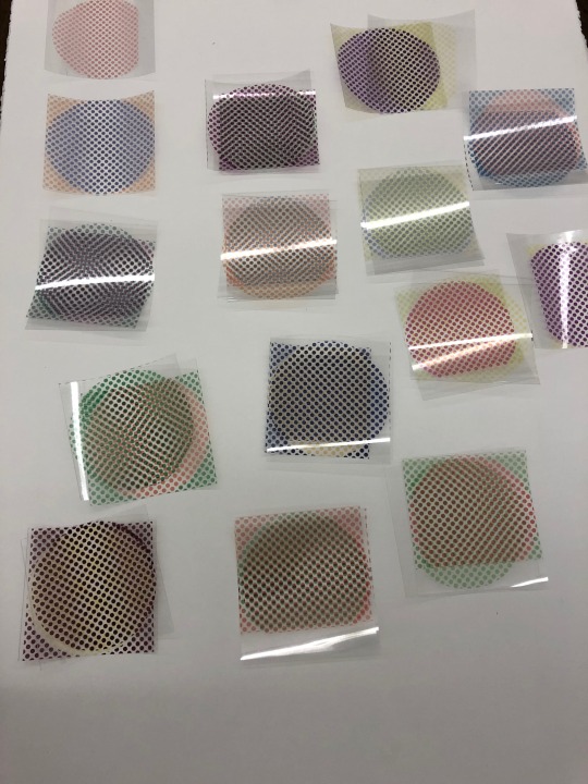
These are the prints that we used to test the overlap of the colors and whether or not the pattern created were visible or not. Some colors proved to be very successful over other color combinations.
The lighter colors such as:
-Orange
-Pink
-Yellow
Were not successful because they diffused and didn’t create contrast.
youtube
This test shows a good match between purple and red,
Whats in a color ?
youtube
This test is some what successful. It shows color variation but it gets too dark at times. Artistically it may seem interesting, but the idea gets sort of lost. We considered lowering the opacity on the colors, but it would mean having very soft colors overlapping, and that would not yield good results.
youtube
This image shows a failed test. The green is hardly visible and it does not help the purple blend in, in order to create patterns. After this we decided to stay away from the light colors.
youtube
Black dots, surprisingly gave us some really good results. The white in the background really makes the dots pop. We are going to do some variations and see what happens when we play with outlines and gray-scales.
0 notes
Text
ASSIGNMENT 4 & 5 : CONNECTED ARTIFACTS
CONCEPT_4 : PIXEL // FINAL CONCEPT // PROTOTYPE
( Christopher Meza + Arghavan Ebrahimi )
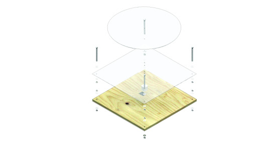
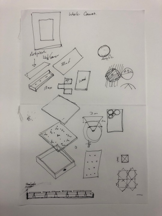
EXPLODED ISOMETRIC DRAWING
As we mentioned on earlier posts, this idea became an extension of earlier concepts.
The image above shows the full spectrum of parts required to build the art installation. (Stepper motor not drawn to scale / proximity sensor not included. )
During the design process we questioned every aspect of the device.
We considred things such as:
-Base thickness.
-Base Material.
-Length of bolts
-Thickness of acrylic.
-Dimensions of the installation itself.
Our solution was to build a device sturdy enough to be able to hold multiple electrical components. That required a 3/4″ thick plywood base. Additionally, the dimensions of 24″ x 24″ was a result of laser bed constrains and industry standard material dimensions of acrylic.
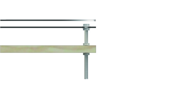
This is an elevation view of one of the corners of the art piece/ canvas, as we have started calling it. The assembly is simple, yet functional. The bolt is close to 6″ in length; seemed fit for proportion. The bolt allows us to screw nuts and washers in order to hold the acrylic sheet at the right height across all four corners. Additionally, the length of the bolt allows us to create create a gap between the board and the wall in order maintain the electrical components clear of anything that might damage them. The same happens in the front where the servo/stepper motor is housed.
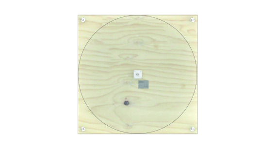
This image depicts a plan drawing of the device. At this point we are conversing about whether or not we should paint the plywood white, or if we should leave it as is. At this point we are getting ready to test the color pixels to see which color schemes work better at creating contrasting patterns.

We also concluded that in order to have a cleaner device/canvas, almost all of the wiring would have to move to the back. Rethinking the arrangement of the electrical components and their relationship to one another, is a challenger we are currently facing. The prototype will soon be fabricated. For now we will continue with the pixel tests.
In addition to that, we have also considered the parameters that come with an actual installation. That said, we are now thinking of a way that the canvas can be displayed. We are thinking it could be hung, or it could simple be elevated on a platform. In perfect setting, the bolts would go straight into the wall along with the wiring. We cannot do that exactly, so we are working on that.
0 notes
Text
Oscilloscopes - Conception of the Idea

When exploring methods of facilitating interaction between two people, we knew we wanted to use both audio and visual media to represent an abstraction of human conversation. We tossed around some ideas for games involving an audio sensor. But, upon further research into audio-visual media, we discovered a handful of installations that were using oscilloscopes as a means to represent music through visualized sound waves.
Artists such as Andrew Duff use analog synthesizers to control the X, Y, and Z axis of an oscilloscope. Each axis has a unique sine-wave input, the culmination of these inputs results in a 3D composition comprised of each sine wave. As the sine waves begin to modulate, so does the image. Below are a series of visual pieces Duff has created with his oscilloscope.


Heavily inspired by this piece, we began thinking of ways we could use the human voice to create a visual composition between two individuals. By using just the X and Y inputs, each voice could control one axis, effectively rendering the interaction of two human voices as a single visual abstraction.

Luckily, old CRT televisions from the 1990’s use very similar technology to an oscilloscope. We can modify these televisions to control the X and Y coordinates of their screens using audio inputs such as microphones, instruments, or anything else that produces noise. The ultimate goal is to create an interface for two individuals to use their own voices to create a collaborative composition, thus facilitating human interaction through their own vocal cords.

Below is a link to Andrew Duff’s live show. Watch a few minutes of it to see these visual pieces become animated, and also see how they relate to the audio signal.
youtube
1 note
·
View note
Text
ASSIGNMENT 4 & 5 : CONNECTED ARTIFACTS
CONCEPT_4 : PIXEL // FINAL CONCEPT // SKETCHES
( Christopher Meza + Arghavan Ebrahimi )
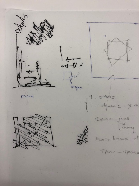
STATIC + DYNAMIC
We went back, dismantled our political idea, and began to rethink the simplicity within the early stages of our concept.
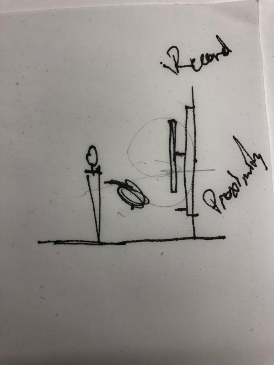
This is the basic idea of our final concept. An artistic piece that could be both static and dynamic; depending on its response to user proximity.
Rather than having the device respond to its own proximity sensor. We decided that in order to truly connect two devices remotely, the input of one sensor would be the input for the opposite art piece.
These are the first sketches of a prototype. We began to think about the dimensions and the assembly of the artistic pieces.

While developing the frame of the art piece and all of the components necessary to build the device, we were also very conscious of the location of the electrical components.
I don’t want to say that form follows function, but the functional arrangement of the electrical components was a constant back and forth of trial and error. That in the end, relied heavily in the dimensions of the board and the dimensions of the electrical components alike.
We only had so much plywood, and so much acrylic, and at the same time, the length of the wired we had at our disposal were only a certain length.
The image above drew our interest into the possibilities that overlapping fields of circles could create.
0 notes
Text
ASSIGNMENT 4 & 5 : CONNECTED ARTIFACTS
CONCEPT_3 : BLURRED MEDIA // TESTS + FAILURES
Again, too complicated for the time frame.
( Christopher Meza + Arghavan Ebrahimi)

IDEA -MIKHA JEON - His work inspired us in understanding anaglyphs in motion.
http://seungbinjeon.com/idea/
BELLOW ARE SOME OF OUR TESTS.
Our tests included a series of clear vinyl prints.
The series will show a mix of digital illustrations and their printed counterparts.

Senator Bernie Sander political cartoon.

Printed images. Here we can see that the saturation of the colors is pretty heavy in some spots, in others the black pigment has a higher contrast when overlapped.

Due to the lack of contrast between these images, we decided to terminate this idea. We think that there is good potential in the premise and the metaphor that was developed in order to critique current political broadcasting. Due to our failed test, and limited timeline, we do not think we would be able to conceive a clear idea since the success relied on impeccable color prints.

These were the lenses we originally used to test our idea, as well as some of the film pieces we used to develop the prototypes for the mask.

Here we can see all of the images overlapped. In order to create political contrast, we decided to use images of our current President, President Donald Trump.
From an artistic approach, we don’t think that the over-saturation created by the overlapping images would have worked.

Nevertheless, we continued to build on this idea, and we took what we learned about the contrast of our test and began to narrow down a cleared intervention.
0 notes
Text
ASSIGNMENT 4 & 5 : CONNECTED ARTIFACTS
CONCEPT_3 : BLURRED MEDIA // A CRITIQUE ON POLITICAL BROADCASTING (This is where it gets political)
( Christopher Meza + Arghavan Ebrahimi)
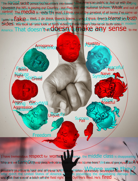
This is the illustration for the preliminary concept.
The idea here, was to start a dialogue between to people with opposing view points. The dialogue would be facilitated with the art piece. As one person approaches, only one side of the machine works, and as another approaches, a different piece gets actuated.
The images and the letters were supposed to work as anaglyohs, and depending on the screen, the viewers would only be allowed to see one set of objects move until another arrived. Then the whole picture would be clear.
As the circles overlapped, in certain instances, the images would be readable by both users.

The common colors used for an anaglyph were red and blue. And as the image above, they fit in perfectly into our political climate.

The image above depicts an earlier concept that required multiple circles. We narrowed it down to one circle.
Again, the idea would be to start a conversation between to opposing viewpoints.
Looking at the larger metaphor, we wanted to show that true movement could only be perceived through equal communication. And even if there were disparities, there would also be agreements. All of which, at the same time, make a critique of the way media has blurred both sides of politics.

Above is an anaglyph of fake news.

These sketches begin to rethink the idea of what the color mask would do in this scenario.
0 notes
Text
ASSIGNMENT 4 & 5 : CONNECTED ARTIFACTS
CONCEPT_3 : BLURRED MEDIA // A CRITIQUE ON POLITICAL BROADCASTING (INSPIRATION)
( Christopher Meza + Arghavan Ebrahimi)
INSPIRATION.
vimeo
https://bea.st/constructive-interference
This video shows how the constructive interference piece was built.
youtube
We wanted to take a similar approach but trick the eye by making the piece itslef move while the user moves.

BRINGING OPPOSING VIEWS TOGETHER THROUGH THE SAME LENS.
This third, and almost final concept was a combination of several ideas. Our first source of inspiration was a renaissance perspective drawing device.

The image above depicts the Renaissance View finding Device and its multifaceted adaptation in the way engineers, scientists, and architects view and approach their published works.
This tension between perspective and communication made us question what the “image” or “object” would be; if there was going to be an image or object at all. Finding a justification was a bit arduous, as designers we didn’t want the design to be washed down by merely proposing that the distortion or communication would simply be “abstract.”
Still holding on to this idea, we decided to look else where. We initially began to look for practical vision enhancing or disruptive devices. With that approach in mind we found anaglyph’s. An anaglyph is “ a stereoscopic photograph with the two images superimposed and printed in different colors, producing a stereo effect when the photograph is viewed through correspondingly colored filters.”

The image above depicts a mural painted in a red and blue anaglyph style. each lens allows for a limited view of the image, When paired together a full picture is seen.
At first we wanted to replicate an existing image and allow its display to change based on the presence of an individual. By doing so, we ran into issues of intent. The image itself had to inform more than just a color change in order to transcend its purpose from one location to another.

Additionally, (and here is where it gets fun) we though about adding some sort of movement to the artistic piece that could create different visual conditions.
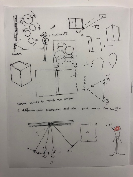
The sketch above shows some of the first ideas we had.
The circles show that we wanted to have some sort of movement; depending on proximity.
The sketch at the bottom depicts a potentiometer. This idea was an early attempt at understand the analog tensions created art, the viewers, and the possible frame that could alter the piece and the perspective through some sort of kinetic interface.
Eventually we ran into the idea of having the viewer wear a mask. (As seen in the red dot) such mask would work as a metaphor for some sort of view, while another mask would represent another view.

Meaning that in order for the whole art piece to work, two colors or “views” would have to be present in order for the art piece to move entirely.
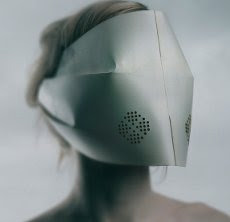
This image is an early concept that we found online. Unlike this one, out mask would be created our of a color film, either red or blue.

Basic diagram of an anaglyph.
0 notes
Text
Forced Equilibrium_Assignment 4_Alaa+Stephen_Concept
IN PROGRESS

The concept that drove the conception of this project was the physical feeling of telepresence that one person can ensue upon another over a long distance.

0 notes
Text
Assignment 4_Flow Meter Testing.
After acquiring the new flowmeter as an input sensor, it was our next task to connect it to the Arduino uno board in order to test its functionality.
youtube
once connected to the Arduino board, and after modifying the Arduino code to receive data from the flowmeter, we gradually increased the flow of water from the test syringe into the flow meter and back out and into a plastic container.
As shown in the above video, the sensor successfully measured the amount of water passing through it (mL).
We will be using this sensor in order to record the amount of water leaving the syringe after pressure is applied and mapping this flow information onto the peristaltic pump range in order to push the same amount of water through the system to impose similar force on the syringe on the opposite end of the mechanism.
0 notes
Text
ASSIGNMENT 4 & 5 : CONNECTED ARTIFACTS
CONCEPT_2 : ACTIVE WHERE (wear) // THESIS APPLICATION
( Christopher Meza + Arghavan Ebrahimi)

GARMENTS THAT CAN TALK TO OUR LOVED ONES FOR US.
The concept, in theory, makes sense. The issues we ran into was the application and placement of sensors, as well as the length of time we had to complete the project. As with the number of lights, with our previous concept, we ran into the issue of having too may sensors on the jacket.

Our solution to the number of sensors would have been electric fibers that are able to detect when they are bent. The availablity and manipulation of a new material would have taken too long, and it would have been too difficult to effectively solve within our timeline.
Conceptually, however, if we were to use a different type of motion sensing fabric(fibers) the location of such fabrics would be the same as the diagram above.

Using this design by Adidas we began to think about the aesthetics of the jacket and the possible ranges of motion. Essentially, the jacket became our template for exploring possible real life applications.
Additionally, the puffy-ness of the jacket, in our intuitive approach, would be able to mitigate the constraints of using wires, motherboards, and a battery. Aesthetically, our intention was to make these components as invisible as possible.

This diagram shows the possible way in which the the sensors, the motherboard, and the battery would be wired together.

The illustration above shows the possible input and out-put connections and responses over two motherboards that talk to each other remotely through a server.
After further development we concluded that, again, we had too many sensors, as our previous concept. Additionally, the semantic understanding of the relationship between gesture and light outputs would be a hard concept to prove with a tight deadline.
0 notes