
IPCS through its research oriented and progressive approach offers perfect automation solutions to a vast array of industries which include but are not confined to software, marine and construction engineering. We have been providing industries with services ranging from proposing and installing to the absolute commissioning of automated system, completely adhering to the industry standards. IPCS provides its customers with a plethora of products- HMI systems, Programmable Logic Controllers (PLCs), DCS systems, Supervisory Control and Data Acquisition (SCADA), drives, sensors, DCS systems and much more. We also offer Lightning and Surge Protection Devices from Dehn, Germany. IPCS aims to avail a definitive intelligent solution for eradicating the energy losses incurred in industries and we have always succeeded in the same. Apart from all these, we conduct numerous training programs in corporate companies and also for professionals in the areas of PLC, SCADA, DCS, HMI, Drives, Embedded, Panel Designing, Process Control, Electric Controls and Industrial Networking.
Don't wanna be here? Send us removal request.
Statistics
We looked inside some of the posts by ipcsautomation-blog and here's what we found interesting.
Average Info
Notes Per Post
2
Likes Per Post
2
Reblog Per Post
0
Reply Per Post
0
Time Between Posts
6 days
Number of Posts By Type
Photo
3
Text
14
Last Seen Tumblr Blogs


Fun Fact
Premium Tumblr themes are available from anywhere between $9 to $49.
Photo


IPCS Automation Lab Photo
1 note
·
View note
Photo


IPCS have signed MoU with SNS College of Technology for their PLC , SCADA, HMI, VFD Training
#plc training#vfd training#DCS training#hmi training#Automation Training#Calibration and testing#control panel design
0 notes
Text
Solar Charge Controller
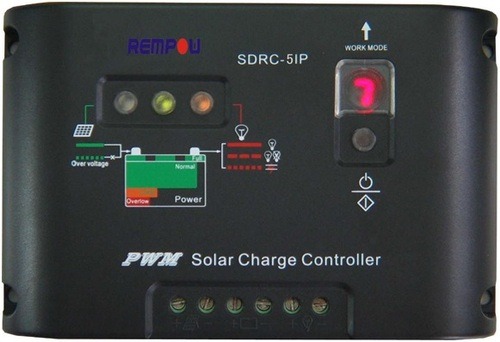
Since the brighter the sunlight, the more voltage the solar cells produce, the excessive voltage could damage the batteries. A charge controller is used to maintain the proper charging voltage on the batteries. As the input voltage from the solar array rises, the charge controller regulates the charge to the batteries preventing any over charging. Modern multi-stage charge controllers Most quality charge controller units have what is known as a 3 stage charge cycle that goes like this : 1) BULK During the Bulk phase of the charge cycle, the voltage gradually rises to the Bulk level (usually 14.4 to 14.6 volts) while the batteries draw maximum current. When Bulk level voltage is reached the absorption stage begins. 2)ABSORPTION During this phase the voltage is maintained at Bulk voltage level for a specified time (usually an hour) while the current gradually tapers off as the batteries charge up. 3)FLOAT After the absorption time passes the voltage is lowered to float level (usually 13.4 to 13.7 volts) and the batteries draw a small maintenance current until the next cycle. MPPT Maximum Power Point Tracking Most multi-stage charge controllers are Pulse Width Modulation (PWM) types. The newer Maximum Power Point Tracking (MPPT) controllers are even better. They match the output of the solar panels to the battery voltage to insure maximum charge (amps). For example: even though your solar panel is rated at 100 watts, you wont get the full 100 watts unless the battery is at optimum voltage. The Power/Watts is always equal to Volts times Amps or P=E*I .With a regular charge controller, if your batteries are low at say 12.4 volts, then your 100 watt solar panel rated at 6 amps at 16.5 volts (6 amps times 16.5 volts = 100 watts) will only charge at 6 amps times 12.4 volts or just 75 watts. You just lost 25% of your capacity! The MPPT controller compensates for the lower battery voltage by delivering closer to 8 amps into the 12.4 volt battery maintaining the full power of the 100 watt solar panel! 100 watts = 12.4 volts times 8 amps = 100 (P=E*I). The Charge Controller is installed between the Solar Panel array and the Batteries where it automatically maintains the charge on the batteries using the 3 stage charge cycle just decribed. The Power Inverter can also charge the batteries if it is connected to the AC utility grid or in the case of a stand alone system, your own AC Generator. If you are using four 75 to 80 Watt solar panels, your charge controller should be rated up to 40 amps. Even though the solar panels dont normally produce that much current, there is an edge of cloud effect. Due to this phenomenon I have seen my four 6 amp panels (4*6=24) pump out over 32 amps. This is well over their rated 24 amps maximum. A good 3 stage 40 amp Charge Controller will run about $140 to $225 depending on features like LCD displays. For eight 75 to 80 watt solar panels you would need two 40 amp Charge Controllers to handle the power or you could increase your system voltage to 24 volts and still use just one 40 amp Charge Controller.
More News & Events on www.ipcsautomation.com PLC SCADA VFD HMI DCS TRAINING QATAR - COCHIN - CALICUT - COIMBATORE - MUMBAI
1 note
·
View note
Text
Differential Pressure Level Transmitters

The importance of level measurement cannot be overstated. Incorrect or inappropriate measurements can cause levels in vessels to be excessively higher or lower than their measured values. Vessels operating at incorrect intermediate levels can result in poor operating conditions and affect the accounting of material.
The level of a liquid in a vessel can be measured directly or inferentially. Examples of direct level measurement include float, magnetostrictive, retracting, capacitance, radar, ultrasonic and laser level measurement technologies. Weight and differential pressure technology measure level inferentially. All have problems that can potentially affect the level measurement. Differential pressure level measurement technology infers liquid level by measuring the pressure generated by the liquid in the vessel.
For example, a water level that is 1000 millimeters above the centerline of a differential pressure transmitter diaphragm will generate a pressure of 1000 millimeters of water column (1000 mmWC) at the diaphragm. Similarly, a level of 500 millimeters will generate 500 mmWC. Calibrating this differential pressure transmitter for 0 to 1000 mmWC will allow it to measure water levels of 0 to 1000 millimeters. Using the available information properly is another potential problem. Some years ago, distributed control system inputs were incorrectly configured to correspond to the maximum transmitter spans. Aside from using incorrect values, the levels should have been expressed in percent. Using absolute level measurement units such as inches, feet, millimeters or meters increases the potential for error because operators must remember the height of each vessel to put the level measurement in context with the vessel. This can easily become overwhelming and cause operator errors because plants often have hundreds of vessels.
Differential pressure measurement is a workhorse of industrial level measurement that is been used for decades and will continue to be used for decades to come.
More News & Events on www.ipcsautomation.com PLC SCADA VFD HMI DCS TRAINING QATAR - COCHIN - CALICUT - COIMBATORE - MUMBAI
#Differential Pressure Level Transmitters#Pressure Level Transmitters#Transmitters#Level Transmitters
0 notes
Text
MULTIHOP ETHERNET DATA RADIO

The MultiHop Ethernet Data Radio system provides extremely reliable communication in large plants, over long distances, or through difficult terrain. A network can easily cover many square miles and has a raw bit rate of 300Kbps. Master, Repeater, and Slave Radios All radios can be configured as a master, repeater, or slave radio. Master Radio: Every network has only one master radio and all data is routed to or from the master. Because of this, the network will have better throughput if the master radio is connected to the PLC or HMI that generates the most data traffic. Repeater Radio: Repeater radios are slaves that also repeat. Although it is possible to use many repeaters in a network, it is usually better to carefully define only a few devices as repeaters to help the network form faster and result in fewer repeated messages. Repeating a message many times unnecessarily slows down the network. Repeater radios should be stationary and always on; a moving or powered off repeater causes a slight delay in communications while the network reforms through other repeaters. REPLACING THE ETHERNET CABLES WITH THE MULTIHOP ETHERNET RADIOS 1. Remove the Ethernet cables from the switch and plug the cables into two MultiHop Ethernet Data Radios placed at least 6 feet apart. Do not change the IP address of the radios. They will relay all Ethernet traffic by default. Think of them as simple cable replacements. Flexibility » Each model can be selected to be a Master, Slave or a Repeater » 10 to 30 V dc or a low power 5 V dc mode for Solar Power applications Ease of Use » No software or IP addressing required for deployment » Built in LCD interface to display radio signal strength results Applications » Ethernet Wire Extension and Replacement » Remote I/O » Message Display Signs » SCADA (PLCs, Modbus, Ethernet IP) » AGV Integration » Electric, Oil, and Gas Utilities/Metering
More News & Events on
www.ipcsautomation.com PLC SCADA VFD HMI DCS TRAINING QATAR - COCHIN - CALICUT - COIMBATORE - MUMBAI
0 notes
Text
SENSOR COMBINATIONS AND MINIATURIZATION
http://www.ipcsautomation.com/
New sensor combinations are emerging in the sensor market as combining those cuts the overall costs of the sensors. Putting several sensors on a package, such as accelerators and gyroscopes is becoming more commonplace. Miniaturization is an interesting trend. Miniaturization of sensors is enabling some of the innovative sensor packaging and devices. Innovations in gaming, such as in the X-Box Connect, which brought in multiple types of sensors to deliver rich fidelity, are moving into mobile devices as well. Traditional fitness is seeing the same thing as key vital signs and biometrics are becoming visible. Miniaturization of sensors combined with enhanced fidelity of devices allows product manufacturers and service providers to experiment with devices and offer compelling and fulfill compelling and specific needs. Bosch MEMS sensor: Bosch has rolled out a MEMS sensor that combines pressure, humidity, and temperature measurement in a single component. The BME280 is aimed at handsets and wearables where it is to be used for greater control as well as sports and fitness use cases. Its humidity sensor measures relative humidity from 0 to 100 percent and from -40°C to +85°C with less than 1 second of response time. The humidity measurement accuracy is plus or minus 3 percent, with a hysteresis of 2 percent or more, and a temperature reading accuracy within half a percent Celsius. The device’s pressure is intended to offer floor-level tracking for indoor navigation. The relative accuracy of pressure readings is plus or minus 0.12 hPA, which equates to plus or minus 1 meter of altitude difference at a resolution of 1.5 cm. The device comes with I2C and SPI serial digital outputs. Its packaging measures 2.5mm by 2.5mm with a height of 0.93mm in an 8-pin LGA package. More
News & Events on www.ipcsautomation.com PLC SCADA VFD HMI DCS TRAINING QATAR - COCHIN - CALICUT - COIMBATORE - MUMBAI

0 notes
Text
Texas Instruments launches industry first highly integrated NFC sensor transponder
http://www.ipcsautomation.com/
Texas Instruments (TI) announced the industry first flexible high frequency 13.56 MHz sensor transponder family using NFC Technology. The highly integrated ultra-low-power RF430FRL15xH system-on-chip (SoC) family combines an ISO 15693-compliant Near Field Communication (NFC) interface with a programmable microcontroller (MCU), non-volatile FRAM, an analog-to-digital converter (ADC) and SPI or I2C interface. The dual-interface RF430FRL15xH NFC sensor transponder is optimized for use in fully passive (battery-less) or semi-active modes to achieve extended battery life in a wide range of consumer wearables, industrial Automations, medical, Sensors and asset tracking applications. Near field communication (NFC) is basically a short-range, high-frequency (13.56 MHz) RFID technology that allows for the exchange of information between two NFC-enabled devices. Non-volatile FRAM combines the speed, flexibility and endurance of SRAM with the stability and reliability of flash – while providing the industrys lowest power consumption and virtually unlimited write cycles. FRAM allows developers to create products that can quickly store sensor data and enables easy configuration of the transponder and sensors to meet any applications needs. Integrating NFC sensors into medical, industrial and asset-tracking applications. Developers can now design products that require an analog or digital interface, data-logging capabilities and data transfers to an NFC-enabled reader. The RF430FRL15xH transponder acts as a sensor node for these applications and generates an IoT-ready solution when an NFC-enabled device pushes the data to the cloud. In medical or health and fitness applications, the RF430FRL15xH can be used in disposable patches that sense temperature, hydration and more. This allows patients to monitor and share vital data securely with their health providers. The device monitors and logs data in local storage (FRAM) before transferring it to an NFC-enabled tablet or Smartphone. The RF430FRL15xH enables the design of maintenance-free and hermetically sealed galvanic isolated sensor systems in the industrial markets. These sensors are powered out of the RF field and communicate wirelessly through NFC to collect and log data. Logistics applications such as food tracking need constant temperature control, which can be monitored and logged with the RF430FRL15xH transponder. It allows the design of highly integrated, size-optimized and easy-to-use data loggers with several sensors that connect to NFC-enabled devices and readers throughout the distribution channel.
More News & Events on www.ipcsautomation.com PLC SCADA VFD HMI DCS TRAINING QATAR - COCHIN - CALICUT - COIMBATORE - MUMBAI

0 notes
Text
SignalFire: Wireless Remote Shutdown System
http://www.ipcsautomation.com/
Remote Shutdown System (RSDS) can shut down wells or other assets remotely with the fail-safe logic necessary for wireless operation of critical systems. In challenging environments, such as oil fields, equipment often needs to be shut down remotely. For instance, when a tank that collects oil or water from several wells becomes full, wells must be shut down to prevent overflow. Because of the oil-field layout, the decision to shut-in a well (usually conducted near the tanks) is often made far away from the actual wells. For this type of monitoring and control, SignalFire wireless telemetry offers the remote shutdown system (RSDS), which can shut down assets remotely with the fail-safe logic necessary for wireless operation of critical systems. Eliminating the need for costly conduit runs, this long-range (3+ miles) wireless telemetry system can be configured with either a PLC monitoring system (shown) or a gateway-controlled standalone system that can monitor inputs and generate control commands autonomously. When configured as a PLC-controlled system, a local PLC makes the decision to shut down the remote wells. If monitoring tanks in the oil fields for overflow conditions, tank sensors could be directly connected to the PLC that monitors data and decide if the tank is in an alarmed state. Alternatively, the data could be sent wirelessly, with the PLC obtaining tank-level data from the Gateway. The PLC, then, determines whether the well should be operating or shut-in, and sends the proper command to the shutdown nodes located at the well site. The system interfaces with any type of sensor and transmits the data wirelessly to a gateway. When operating autonomously, the gateway generates commands and offloads data to a PLC. The gateway can be configured to additionally send signals to remotely-located shutdown nodes that will shut-in the well. When the SignalFire RSDS is configured as a PLC-controlled system, a local PLC makes the decision to shut down the remote wells. If monitoring tanks in the oil fields for overflow conditions, tank sensors could be directly connected to the PLC that monitors data and decide if the tank is in an alarmed state. Alternatively, the data could be sent wirelessly, with the PLC obtaining tank-level data from the Gateway. The PLC, then, determines whether the well should be operating or shut-in, and sends the proper command to the shutdown nodes located at the well site. Both RSDS communication systems support a large number of wireless sensors and incorporate SignalFire’s exclusive CommSafe software that guards against system failure if wireless communication is interrupted. In addition to being used extensively in upstream oil and gas applications, the RSDS is ideal for water-tank control and industrial situations where tank monitoring and pump control are necessary, says the company. More News & Events on www.ipcsautomation.com PLC SCADA VFD HMI DCS TRAINING QATAR - COCHIN - CALICUT - COIMBATORE - MUMBAI

0 notes
Text
Low Power Factor Impacts
http://www.ipcsautomation.com
As well as the power that is used in equipment (heating, lighting, driving motors), known as real power, a site may also draw power which is not directly used, known as reactive power. The combination of two is known as apparent power. Power Factor is the relationship between real and apparent power (kVA). If your site has a poor power factor, you could be paying for energy that cannot be used.When you pay for a latte, the last thing you want is more froth than coffee. The same thing can be said about power. Froth on a latte is like wasted energy.Power factor is the ratio of real power to the apparent power flowing to the load from the source. This is an important piece of knowledge for manufacturers because a low power factor raises your plant or factory’s power bill.Taking control of and monitoring Power Factor can lead to reduced kVA demand and therefore reduced electricity costs. Improving Power Factor can lead to savings on your business electricity bill.Installing Power Factor Correction Equipment can be a cost effective measure to reduce your electricity bill.Power factor (PF) is measured between 0 and 1.0 (usually given as a percentage, with 100 percent or 1.0 being unity). If your facility’s PF is below a certain level (typically 95-96 percent), your utility will charge a reactive power fee. This is because a low PF represents an inefficient load source that is drawing reactive (i.e. non-working) power that the utility has to make up for.The best use of power in an AC circuit is when the voltage and current are in alignment. However, much of your electrical equipment is probably delaying as it draws current, meaning that the current and voltage are misaligned and causing it to draw more current to operate.The bottom line is that your PF percentage shows you how much of the total current you are drawing is being used to do real work. For example, a PF of 80 percent means that 20 percent of the current flowing into your facility is non-working power. Power Factor Correction Benefits: Beyond lowering your facility’s electricity bills and avoiding reactive power fees, increasing your facility’s power factor also reduces carbon emissions, reduces I2R losses in transformers and electrical distribution equipment, and reduces heat in cables, switchgear, transformers and alternators which can prolong the lifespan of equipment.
More News & Events on www.ipcsautomation.com PLC SCADA VFD HMI DCS TRAINING QATAR - COCHIN - CALICUT - COIMBATORE - MUMBAI

0 notes


Text
Auto CAD and Eplan - Duration - 30 hrs
Our training is aimed at engineers practicing embedded software as well as those planning to enter the embedded field. The training presents practical sessions and techniques for use in designing, implementing, integrating, and testing of modern embedded systems. After successfully completing the training, the participant will be proficient in handling Embedded Projects independently.
MCS-Versions - Assembly Language/ Embedded C
INTEL 8051 mcus.8051/89c51 architectures,
Introduction to embedded c.
System development, PIC microcontrollers.
Microchip PIC Architecture LEDs, Loads, timer and counters.
Interrupt service routine; seven segment Displays.
4X4 Matrix keyboard Conversion of Hex to BCD, HEX to ASCII.
HEX to Decimal values, 2x16 LCD Interfacing, LCD with Matrix key board.
UART and Serial communication.
PC with microcontroller and exchanging data on different baud rates.
Frequency counter
Controlling Devices from PC using serial communication.
Pulse Width Modulation.
Servo motor and Stepper Motor control Interfacing of ADC
Different type of sensors.
DEVOLOPMENT TOOL FOR MCS-8051 -KEIL
MICROCHIP - PIC - Assembly Language/ Embedded C
Introduction to embedded C.
System development.
PIC microcontrollers.
Microchip PIC Architecture LEDs, Loads, timer and counters.
Interrupt service routine; seven segment Displays.
4X4 Matrix keyboard Conversion of Hex to BCD, HEX to ASCII.
HEX to Decimal values, 2x16 LCD Interfacing, LCD with Matrix key board.
UART and Serial communication.
PC with microcontroller and exchanging data on different baud rates.
Frequency counter.
Controlling Devices from PC using serial communication.
Pulse Width Modulation.
Servo motor and Stepper Motor control Interfacing of ADC
Different type of sensors
DEVOLOPMENT TOOL FOR PIC CONTROLLERS - MPLAB IDE.
Real Time Operating System (RTOS)
ARM Processors / Robotics
Register Now : www.ipcsautomation.com/Online Registration
Call Us : +919846770771, +919539096664
0 notes
Text
VFD Installation Professional - Duration - 30 hrs
Today Conventional motor starters are replaced by energy efficient Variable Frequency Drives. Variable Frequency Drives can provide maximum starting torque without causing complaint to motor windings. The course contents are
Basic terminology associated with motors and Variable speed drives
Type of Motors , construction and their operating principle
Basic principle of starters and variable speed drives
Methods of starting of motors
Main functions of starters and Variable speed drives
Different types of Drives- Variable Frequency and Variable Voltage drives.
Different control modes of VFDs
Discrete and Continous control schemes.
Effect of long distance cables on VFDs
Diifferent types of braking
Selection of VFDs based on application
Hands on experience on integrated system
Servo motor and Stepper Motor control Interfacing of ADC
Different type of sensors.
DEVOLOPMENT TOOL FOR MCS-8051 -KEIL
Register Now : www.ipcsautomation.com/Online Registration
Call Us : +919846770771, +919539096664
0 notes
Text
Diploma in Marine Automation Systems - Duration - 240 Hrs View Syllabus
The training program is broadly divided into major sessions. Each session is taken by experts with marine experience. Thus we have developed our training program to equip participants develop cost effective design with marine standards. Practical electrical knowledge has traditionally been a weak area for most marine engineers. This program has been specifically developed to fill this acutely felt training need. Covering advanced aspects of shipboard electrical knowledge, this workshop, conducted in a dedicated laboratory, provides theoretical information and intensive hands-on training The participant is exposed to intensive practical training, both, in actually wiring up several types of starters and also in troubleshooting faults induced in them.
Major Sessions in which training imparted are:
Basics
Measuring Instruments - Multimeter, tong tester, Megger etc.
Measuring Element, Measured Value, Desired value, Error as difference of measured value and desired value, means to eliminate the Error- Function of controller.
Open Loop System & Closed Loop Control System.
Electrical
A.C. Fundamentals (Revision)
Understand the fundamental concepts of electrical technology.
Identify symbols, trace and analyze circuit diagrams and troubleshoot electric systems logically.
Study of various electrical equipment - contactors, relays, timers etc.
Wiring up different types of starters with timers.
Troubleshooting on different types of starters-DOL / star-delta / reversible /auto change- over etc.
Generation of power and parallel operation of generators
Layout of M.S.B. and E.S.B.'s.
Air Circuit Breaker -safeties and maintenance.
Motors -types, construction and characteristics.
Starters -DOL and Reduced Voltage Starters, symbols and maintenance.
Secondary batteries – Maintenance.
Tracing various shipboard electrical circuit diagrams.
Project writing by participants.
Generator Automation and Power Management System.
Study of Fire alarm circuits and Fault Finding.
Practical sessions on complicated live marine electrical panel.
Training on Live Main Switch Board & Emergency Switch Board.
Hands on experience on relay controlled protection unit in Main Switch Board (MSB).
Testing of all alarms and safety tips on Main and Emergency Switch Board (ESB).
Shore power supply – connection to Main Switch Board (MSB).
Instrumentation
Proportional Control, Integral Control, Derivative Control & P-I-D Control.
Instrumentation: Temperature measurement, Pressure measurement, Level measurement, Flow measurement and other measuring instruments.
Pneumatic Transmitter, Pneumatic Controller, Methods of determining the controller settings, Malfunction and Trouble-shooting of controllers.
Knowledge of Pneumatic Components and various practical sessions.
Electro-Pneumatic Systems operations.
Study of Pneumatic Controllers.
PID Functions and practical sessions.
Maintenance and trouble-shooting of boiler systems.
Calibration of Pneumatic controllers.
Exercises on different Controllers and Pneumatic Trainer.
Hands on Practice on Latest PLC Controlled Generator Protection Unit (GPU).
PLC / SCADA Automation
Programmable logic controller, detailed study of the Architecture of the PLC and the memory organization in PLC.
Understanding the input/output section of PLC with Practical.
Electrical diagram, wiring diagram and Ladder diagram and their conversion.
Troubleshooting techniques in PLC.
Manual and Automatic control.
Supervisory Control And Data Acquisition (SCADA). Systems
SCADA Programming and development
SCADA and PLC Communication
SCADA system configuration, RTU, communication protocols
Register Now : www.ipcsautomation.com/Online Registration
Call Us : +919846770771, +919539096664
0 notes
Text
Embedded System Design (Crash) - Duration - 30 hrs
Our training is aimed at engineers practicing embedded software as well as those planning to enter the embedded field. The training presents practical sessions and techniques for use in designing, implementing, integrating, and testing of modern embedded systems. After successfully completing the training, the participant will be proficient in handling Embedded Projects independently.
MCS-Versions - Assembly Language/ Embedded C
INTEL 8051 mcus.8051/89c51 architectures,
Introduction to embedded c.
System development, PIC microcontrollers.
Microchip PIC Architecture LEDs, Loads, timer and counters.
Interrupt service routine; seven segment Displays.
4X4 Matrix keyboard Conversion of Hex to BCD, HEX to ASCII.
HEX to Decimal values, 2x16 LCD Interfacing, LCD with Matrix key board.
UART and Serial communication.
PC with microcontroller and exchanging data on different baud rates.
Frequency counter
Controlling Devices from PC using serial communication.
Pulse Width Modulation.
Servo motor and Stepper Motor control Interfacing of ADC
Different type of sensors.
DEVOLOPMENT TOOL FOR MCS-8051 -KEIL
MICROCHIP - PIC - Assembly Language/ Embedded C
Introduction to embedded C.
System development.
PIC microcontrollers.
Microchip PIC Architecture LEDs, Loads, timer and counters.
Interrupt service routine; seven segment Displays.
4X4 Matrix keyboard Conversion of Hex to BCD, HEX to ASCII.
HEX to Decimal values, 2x16 LCD Interfacing, LCD with Matrix key board.
UART and Serial communication.
PC with microcontroller and exchanging data on different baud rates.
Frequency counter.
Controlling Devices from PC using serial communication.
Pulse Width Modulation.
Servo motor and Stepper Motor control Interfacing of ADC
Different type of sensors
DEVOLOPMENT TOOL FOR PIC CONTROLLERS - MPLAB IDE.
Real Time Operating System (RTOS) ARM Processors / Robotics
Register Now : www.ipcsautomation.com/Online Registration
Call Us : +919846770771, +919539096664
0 notes
Text
Industrial Networking - Duration - 30 hrs
This course covers the standard networking devices and protocols in industry. Networking of PLCs is commonly used in Industries for controlling multiple processes. Participants get maximum practical exposure to networking devices and configuration of custom networks.
Need of Networking : brief history
Different types of networking architecture
Topology
OSI model of networking
Networking Hardware
Network Standards
Safety and management concepts of designing a project.
Modbus
Canbus
Controlnet
Ethernet
Profibus
FIP I/O
Proprietary network
Master Slave Configurations.
RTUs - Remote Terminal Units.
Network comparisons
Design cases
Scheme of remote I/O
Design case of Remote I/O
Register Now : www.ipcsautomation.com/Online Registration
Call Us : +919846770771, +919539096664
0 notes
Text
Certified Embedded Design Professional - Duration - 140 hrs
Our training is aimed at engineers practicing embedded software as well as those planning to enter the embedded field. The training presents practical sessions and techniques for use in designing, implementing, integrating, and testing of modern embedded systems. After successfully completing the training, the participant will be proficient in handling Embedded Projects independently.
MCS-Versions - Assembly Language/ Embedded C
INTEL 8051 mcus.8051/89c51 architectures,
Introduction to embedded c.
System development, PIC microcontrollers.
Microchip PIC Architecture LEDs, Loads, timer and counters.
Interrupt service routine; seven segment Displays.
4X4 Matrix keyboard Conversion of Hex to BCD, HEX to ASCII.
HEX to Decimal values, 2x16 LCD Interfacing, LCD with Matrix key board.
UART and Serial communication.
PC with microcontroller and exchanging data on different baud rates.
Frequency counter
Controlling Devices from PC using serial communication.
Pulse Width Modulation.
Servo motor and Stepper Motor control Interfacing of ADC
Different type of sensors.
DEVOLOPMENT TOOL FOR MCS-8051 -KEIL
MICROCHIP - PIC - Assembly Language/ Embedded C
Introduction to embedded C.
System development.
PIC microcontrollers.
Microchip PIC Architecture LEDs, Loads, timer and counters.
Interrupt service routine; seven segment Displays.
4X4 Matrix keyboard Conversion of Hex to BCD, HEX to ASCII.
HEX to Decimal values, 2x16 LCD Interfacing, LCD with Matrix key board.
UART and Serial communication.
PC with microcontroller and exchanging data on different baud rates.
Frequency counter.
Controlling Devices from PC using serial communication.
Pulse Width Modulation.
Servo motor and Stepper Motor control Interfacing of ADC
Different type of sensors
DEVOLOPMENT TOOL FOR PIC CONTROLLERS - MPLAB IDE.
Real Time Operating System (RTOS)
ARM Processors / Robotics
Register Now : www.ipcsautomation.com/Online Registration
Call Us : +919846770771, +919539096664
0 notes
Text
Electrical Control & Panel Designing - Duration - 60 hrs
Duration : 60 hours (3 Hours per day)
1 . Industrial Electrical Controls- design and installation
Basics of Relays, Contactor, MCB, MCCB, ELCB, ACB,VCB etc
Working details of different types of Electric Motors.
Designing of control circuits using Contactors, Relays, Timers etc
DOL, Star Delta Starter designing for 3 phase motors with specification.
Practical wiring session on different controls.
Motor drives- AC drives and DC drives.
Safety and management concepts of designing a project.
2 . Control Panel Designing
Different types of panels.
Basic components to be installed in a panel.
Wiring details of panel.
Specification and physical dimension of components.
Earthing and Cabling of Panels- standard procedures.
P&I diagram preparation.
3 . PLCs in Electrical controls.
Need of PLC in electrical controls.
Basics of PLC.
Architecture- Modules
NO/ NC, Timers, Counters etc
Programming practice
Register Now : www.ipcsautomation.com/Online Registration
Call Us : +919846770771, +919539096664
0 notes