
Statistics
We looked inside some of the posts by ryunochie and here's what we found interesting.
Average Info
Notes Per Post
139
Likes Per Post
116
Reblog Per Post
23
Reply Per Post
0
Time Between Posts
17 days
Number of Posts By Type
Text
14
Last Seen Tumblr Blogs


Fun Fact
There were a total of 171.5 billion posts on Tumblr in 2019.
Text
About Ray-MMD x ExcellentShadow 2
I’m writing a small post this time to share a detail that left me curious for a while: why do people combine ExcellentShadow with Raycast? Does it produce better results?
Interested in the matter, I searched for answers after knowing from a Rebirth artist that ExcellentShadow may or may not improve the overall results, which felt superstitious. I decided to try it myself: I opened my MMD, loaded and set up Ray, and added ExcellentShadow. At first, no change at all in the shadows, everything looked the same when disabled or enabled.
Next, I loaded two physical lights with enabled ExcellentShadow to check, but again, nothing. No changes. If it had a 50/50 chance of working with Ray, then I supposed I was unlucky and didn’t find the ideal setting.
So I asked two of my contacts that are very experienced in Raycast rendering about ExcellentShadow’s interactions with Ray, if there was any. In conclusion, adding it to Ray is redundant, as Ray’s shadows are already very smooth, even smoother if using “boom!” settings. ExcellentShadow’s purpose is overwhelmed by Ray’s nature, not to mention that the in-built physical lights have a soft or hard shadow feature.
In other words, it’s pointless to load ExcellentShadow with Ray, it’ll only consume more resources. I’m open to discussion about this, so if you do that and it actually works with solid proof, let me know by either reblogging this post or privately messaging me on my social media. Peace!
3 notes
·
View notes
Text
RAY-MMD: Rendering Low Lights
Welcome to another Raycast tutorial. This time, we’ll explore rendering low light scenes in MMD and learn together.
Content index:
Introduction
Envision
Theory
Practice
Post editing
Credits
1. INTRODUCTION
Dark ambience is one of MMD’s biggest challenges due to software limitations. Thankfully, Raycast is powerful enough to handle that for us, but you must know what you’re doing. Unlike daylight, controlling both exposure, shadows, contrast and gamma are vital when messing with darkness.
In this tutorial, I’m going to expand on the technique I’ve used in this render for January’s MME contest. I’m not an expert, so please don’t quote me on anything!

2. ENVISION
When creating art, one of the first steps is to have a clear idea of what you’re going for and set realistic expectations too. That’s key in atmospheric renders, when they depend on lights to fullfil their purpose. In MMD, you’ll have to work twice as harder on these type of renders and they won’t look like something out of Blender. Ray is powerful, but still child’s play compared to other softwares and there’s no other way to put this.
So we start building the render with the basic question: “what do I want?”. In this case, I wanted to make make a lonely dark scene with Sugiura struggling in the cold. The green dots are the rule of thirds’ intersections, they focus on his face and hands while dragging attention to the background. The viewer has enough point of interests: the model, the ground and the lamp post.


If you have this stage, you’ll know that Sugiura is far away from that lamppost, but the rather low perspective (24) eases that. The lights are going to trick the viewer into thinking the elements are closer than it seems.
The main goal is to recreate this kind of light, but not leave Sugiura completely in the dark.

3. THEORY
Let’s discuss a bit about how dark ambience should work on Ray. Naturally, you’d open the Time of Night or Sky Night skybox, but both have a strong contrast that might be difficult to tweak if not paying attention.


Time of Night vs Sky Night. Both are similar, the main difference is the stronger contrast in Sky Night. On note of that, the shadows can’t be easily controlled with Sky Night. The user is stuck with this very dark shadow and can only ease it by changing its RGB.
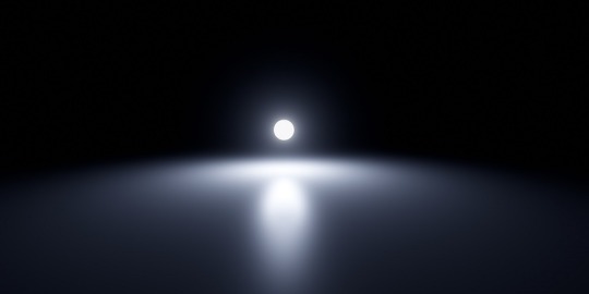
With this in mind, the best option is to use Sky Hemisphere or any other skybox with softer shadows. That’s safer and provides much more control to the user. I highly recommend activating Ray’s eye adaptation for any situation.
The Auto Exposure, commonly called eye adaptation, is a Ray feature that automatically adjusts the exposure of the current scene view to become brighter or darker. This effect recreates the experience of human eyes adjusting to different lighting conditions.
The eye adaptation is disabled by default. To enable it, open ray.conf and scroll down until you find the eye adaptation section. To enable it, change the number to either 1 or 2. In my settings, I picked 2.
// Eye Adaptation // https://docs.unrealengine.com/latest/INT/Engine/Rendering/PostProcessEffects/AutomaticExposure/index.html // 0 : None // 1 : ISO 100 // Middle Gray at 12.7% // http://en.wikipedia.org/wiki/Film_speed // 2 : ISO 100 // Middle Gray at 18.0% #define HDR_EYE_ADAPTATION 2
With eye adaptation, you’ll have an easier time adjusting the exposure, thus working better with dim environments. To further improve the low light experience, disable the sunlight and make the shadows darker using the facial sliders below. The following settings were used in my Sugiura render:


Night works different than day: while in daylight you focus on balancing brightness and saturation, nighttime calls for less saturation (unless neon) and darkness control so the shadows aren’t “exploding dark” on the model. I always keep this quote by Renoir in mind when working with darkness: “no shadow is black. It always has a color. Nature knows only colors... White and black aren’t colors”. In other words, tinted shadows are always welcome.
Thankfully, Ray offers the option to tint shadows using RGB, so you can play with these in your favor. Speaking in very basic color theory, warm lights call for cool shadows and vice versa. Your scene will look much more natural with these.
4. PRACTICE
So let’s put everything we’ve learned so far in practice, as some things we only learn that way. First, I loaded Ray and set it up for basic usage: materials and skybox light. Next, I moved MMD’s default lighting to behind Sugiura to help me work with the physical lights. It acts like the sun for Ray and you’ll build your lights around it. The skybox used is Snowy Park by Freya-Vhal; it’s very useful for night scenes, since it already has blue tones.

Do you notice how the scene is still bright? It won’t get very dark even if disabling sunlight and making the shadows as dark as possible. It’s necessary to decrease the exposure and gamma to darken it. At first, push the slider until you see fit, but don’t forget them yet. You’ll go back to them later for fine tuning.
If struggling to darken a scene, a volumetric cube/sphere fog can help you with that. For that render, I used the atmospheric one to darken the skydome behind the model.
With the scene as dark as you wish, it’s time to light up lamp post behind Sugiura with a pointlight and use the directional light as a support to the right. The left can’t be left completely in the dark though, since there are other lamps ahead. With that, a pointlight was added to balance the darkness.

The bulbs have a strong emissive material plus ObjectLuminous to help with the shine. The jacket has another ObjectLuminous to help me separate it from the background, I don’t want it to become a dark mass around Sugiura’s body. Later, I added ikCluts to help me set up the mood better.

The strong rim light in the next step through PostRimLighting is mostly to separate the elements in Sugiura’s body, to define his coat’s limits within him. As a major bonus, it aids the backlight for a more natural lighting. Rim light is always welcome when the light comes from behind the model. Its other usage is tricky, but I often add it to help with 2D shading as personal preference. When messing with RGB in PostRimLighting, it’s a powerful stylization tool.


The whole atmosphere comes from careful usage of ikCluts to “lift” the shadows and tint the scenario. The lamp post is in evidence because of the BREAK THE COLOR effect, which adds a “souce of light” while darkens the rest as a post effect. It’s very, very useful for low-key rendering when combined with o SelfOverlay Soft and LightBloom.
Do you remember the exposure and gamma? In the advanced stages of the render, it’s important to play around it because it’ll get darker once you load more effects. The initial setting won’t work in most cases and that’s totally fine, you have to fine tune everything until you reach harmony.

5. POST EDITING
Regardless of what others think, post editing isn’t bad and any MMDer that chooses to post edit shouldn’t be seen as inferior. Even professionals retouch their works on Photoshop, GIMP, whatever. In post editing, you can retouch the shadows and brighten the light source.
Finally, I added this painting effect, which made everything much more poetic and dramatic. Can you see how important it is to separate elements with rim light when doing paint 2D?

The lamp post almost blended in the tree, the shapes are very soft. You know it’s a lamp post because of the base, it’s logical. Same goes for Sugiura’s coat, it’s defined thanks to the rim light and would have become a solid mass without it.
6. CREDITS
Render: KS, SEGA, Ai
Eye adaptation documentation by Unreal Engine
1 note
·
View note
Text
NPR: rendering manga panels in MMD
Welcome to the manga stylization tutorial! Here, I’ll cover the core of this style for MMD as well as its usage.
Content index:
Introduction
Effects
Manga Resources
Rendering panels
Building Your Manga Panel
Credits
1. INTRODUCTION
It isn’t any news that many people underestimate MMD’s capabilities and power, not to mention how unexplored the stylization areas are. 3D rendering isn’t only about realistic and semi-realistic rendering! MMD excels in stylization because we have many cel shaders, coloring and screen texture effects in our arsenal.
With manga it isn’t any different! We all know all mangakas have their own styles and this applies to us, MMDers. I’ve been experimenting with manga stylization on and off, trying to find good effect combos.
“But ryuu, why would I want to make manga in MMD??”, you may be asking yourself. And I’ll present you some advantages of doing so:
A viable option for anyone who doesn’t know how to draw, like me.
Unique visuals! A 3D manga looks beautiful, creative and unique when done right.
Think out of the box and add fan panels of your favorite characters to your portfolio!
Since MMD models are very anime-ish, it’s so much easier to make “legit” manga looking panels! Comic theory and post editing are required, but worry not! I’ve got you covered.
2. EFFECTS
If I was to compile some of my manga renders, I’d have an extensive list of effects that produced pleasing results. I’m going to write down every one I can remember, render by render.

Effects: a-toon, excellent shadow, ik hatching, o color halftone 3p, o monochrome, croquis 改, draw style, o selfoverlay, o dlaa, o disalphablend.
Effects: a-toon, drawstyle, o monochrome, o dlaa, o disalphablend, o selfoverlay, croquis 改.
Effects: ray toon, lightbloom, ik hatching, croquis 改, powerdof, o selfoverlay, o color halftone 3p, postrimlighting, o monochrome, snapshot, fxaa.

Effects: ray toon, o monochrome, croquis 改, ik hatching, powerdof, o color halftone 3p, ik watercolor, o selfoverlay, snapshot, o tonemap の改変, fxaa.
Effects: ray toon, croquis 改, o selfoverlay, ik hatching, fxaa, snapshot.

Effects: adult shader, croquis 改 v2, o monochrome, ik hatching, hg sao, o bleach-bypass, o full alphatest, air, clarity.
Did you see how diverse the manga style can be? It’s all up to you how you want to stylize them! The key is making it black and white and adding a toon shader or a very basic one like adult. Don’t forget the contrast work!
If going for Raycast, make sure to use no more than two additional lights. I always add a directional light and go for it. NPR isn’t heavily shaded. If you stack lights, you’ll have double toon shading, which can look weird. I only advise using Raycast if you know what you’re doing.
I know there’s a manga shader, but I personally dislike it, since it doesn’t work well with the models I use.
Also, if you decide to use any bloom effect, make it subtle! We don’t want to give away every 3D aspect of your render, do we?
3. MANGA RESOURCES
So let’s say you want to make a manga panel in MMD. First of all, we need to look for the right resources, so you can post edit the renders for a reliable look. If you aren’t familiar with post editing, I recommend training it and looking at 2D manga scans for reference. The software I use is GIMP, a free and open source one that does as much as Photoshop. It opens Photoshop brushes, so no need to worry about that.
I’ll link a handful of manga resources for post editing!
Speech Bubbles
Manga speech bubbles 3 (image pack)
Manga speech bubbles 3 (GIMP brush)
Tails for speech bubbles
Shaky speech bubbles (GIMP brush)
Shaky speech bubbles (image pack)
Action bubbles (GIMP brush)
Screentones
Digital screentones
Action lines
Action lines 2
Various resources
Shoujo effects (brush)
Tone stars and shapes redux
Manga onomatopee for MMD
Regular fonts
Fonts for editing manga
Manga Temple
Augie
Felt
Wild Words
SFX fonts
Another
Big Fish Ensemble
TrashHand
Vnhltfap
4. RENDERING PANELS
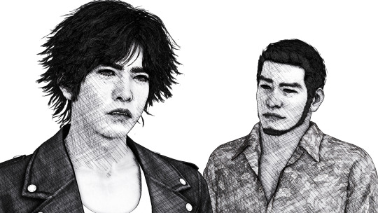
First, we need to find our resolution! A panel can be 1700 x 2400, then you can copy the premade layouts for positioning. In my “oh, you handsome devil!” panel, I rendered each image as the default 1920 x 1080 and resized them later to 1570 x 883 for good margins. Thin or thick margins, that’s up to you.
Important note: when composing your scene, think of the final layout as well! Use the rule of thirds and try picturing where the speech bubbles and other effects will go. Planning is vital when making comics and it’s ok to render many tries before the final image.
Pick a nice set of effects that match your manga style and render! Dynamic shots look awesome with higher perspective. Textures like color halftone greatly improve your manga aesthetic and contrast, but careful not to exaggerate.
For “oh, you handsome devil!” I rendered two panels: one with Soma, one with Yagami and Kaito. The hatching there gives some shading to the models, since I loaded Adult Shader and Hg SAO to emphasize Yagami’s face.

5. BUILDING YOUR MANGA PANEL
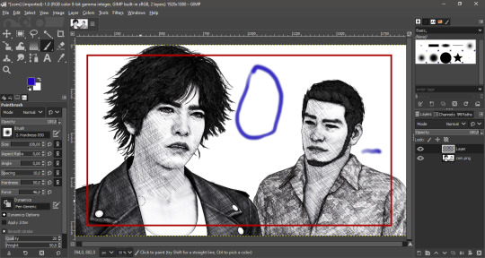
Now in GIMP, I loaded the finished image to show you the rule of thirds guides. Notice how Yagami’s face is the focus, while Kaito isn’t left behind, as he’s close to the intersections. Also, there’s enough empty space to place a speech bubble between them.

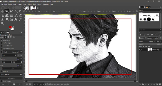
Now let’s talk about basic comic theory! When placing text and speech bubbles, the general rule is to avoid doing so near the edges. This makes reading much easier and focused, unless a difficult reading is intentional. Always imagine an area that limits the edges of your focus so you know where to write your text.

Since you use MMD, I believe you’ve already read at least a manga panel in your entire life. A manga is read from right to left, not from left to right like in western comics.


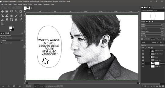
This panel was built using the basic theory. In order to make the text readable, I made it white, added black edges and a slight blur under it. Contrast between text and image is very important in manga for straight forward reading, especially if your render is complex and has many distracting elements.
Back to Yagami and Kaito, the blue marks show where I placed the speech in the finished panel. Can you see how they fit within the red area? The reader can easily pay attention to both models and text. Kaito’s “sure” was placed near the red edges for it was a minor commentary rather than speech.
All you have to do now is to place the speech bubble and write within it! Make sure your text is big enough for the readers. This guide about manga editing has useful tips and free resources for everyone. Feel free to add any other manga effect you’d like, go wild!
Now with Soma, these are the guidelines. It was rendered with enough empty space for background customization. I later added shoujo effects and faded edges with vignette to show he’s in Yagami’s imagination. A daydream if you will! Everything is subtle as not to stray from our objective.

Now when putting everything together in a panel, fit the image within the margins and add a somewhat thick black edge on each. You can position them first, press CTRL + A to select the entire layer and stroke the selection. The line width I used was 15 px.
6. CREDITS
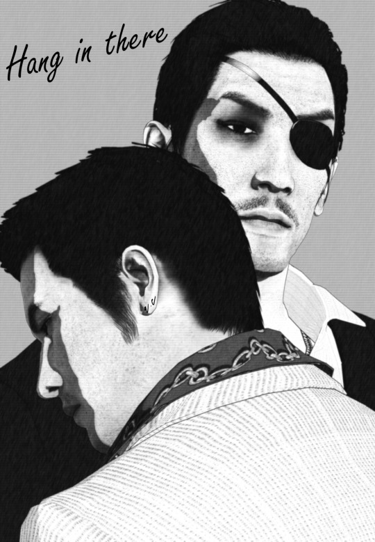
Valentine’s Day Kiryu
Yakuza 0 Kiryu and Majima
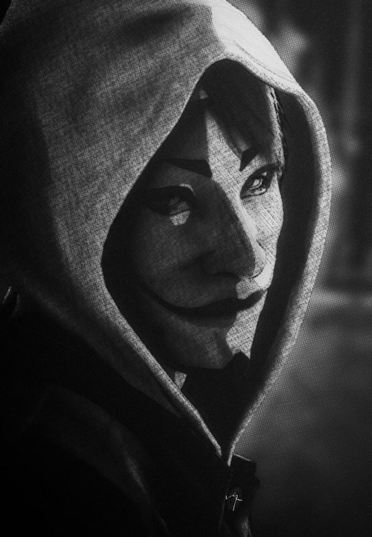
Masked Sugiura
Urban Yagami
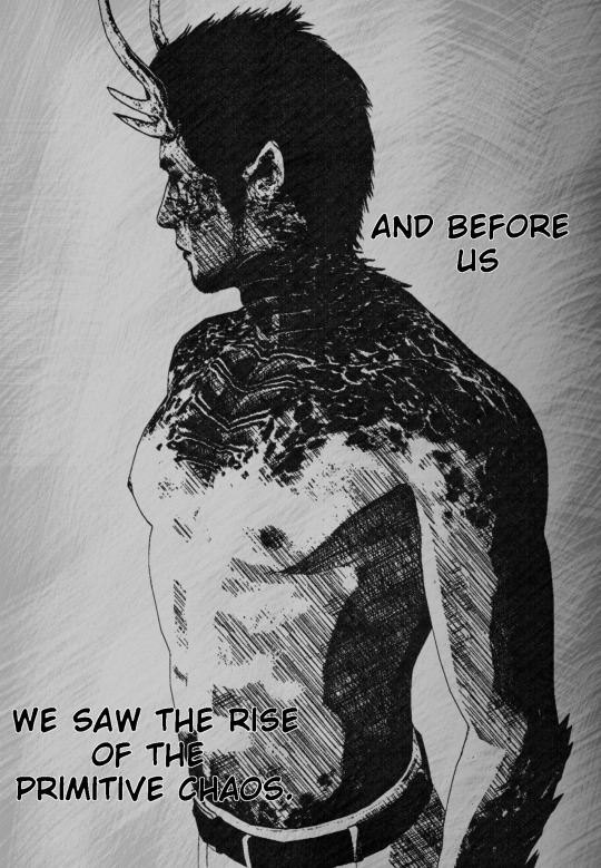
Half-dragon Kiryu
Oh, you handsome devil!
2 notes
·
View notes
Text
CROQUIS 改: doodle like animations in MMD
In this tutorial, I’ll show you how to make an animation in MMD looking like this. This effect can be very useful for animators interested in 2D stylization.
This Croquis mods works with any shader you want and doesn’t require complicated set up.

Before we start, you’ll have to download a modded version of Croquis 改 v2, since the website that held the original download is down nowadays. But don’t worry, it works just fine, as it’s more of a compatibility mod.
Next, download the doodle mod. You’ll notice it only comes with the .fx files. According to the modder, you have to copy-paste these files into the Croquis 改 v2 folder. That’s why we get the usopa compatible version to work as our base.


Make a copy of the usopa mod’s folder before anything. Now, copy all the .fx files and the random.png from doodle mod and paste them into the usopa mod. I recommend doing it little by little, since it looks overwhelming if pasting everything at once.

The next step is to rename the following files and add - usopa to replace the original one:
ColorMapCommon.fxsub → ColorMapCommon - usopa.fxsub
EdgeStrengthDraw.fxsub → EdgeStrengthDraw - usopa.fxsub
SubDraw.fxsub → SubDraw - usopa.fxsub
In the end, your new folder should look like this:

Done? Now just load Croquis normally in MMD and change the X, Y and Z values to 1 to activate the effect.
CREDITS
Yagami by Xelandis, KS and SEGA
Croquis 改 v2 うねうね化 by P.I.P
Croquis改 v2 usopa by たじゃっぴ
21 notes
·
View notes
Text
Fake normal mapping on textures and other tricks for MMD
In this tutorial, I’ll show you how to improve textures with a normals-on-texture technique I’ve developed. I’ll focus on game ports, since they need it the most.
Content index:
Introduction
Applying The Technique
Useful Tricks
Credits
1. INTRODUCTION
In 3D, a normal map is a texture mapping technique very useful for adding details to meshes without using more polygons. It’s an “improved” bump map, which simulates bumps and wrinkles on the object’s surface.
Everyone knows MMD doesn’t support native bump or normal mapping, meaning the user only achieves it by using a shader and applying the texture as spa. However, not every shader has normal map support, plus a low-end user can’t have it without heavily (CPU) shading the model.
With that in mind, I developed a lifesaving technique for those with weaker hardwares. Or if you want to simply keep your normals while playing with other shaders.
2. APPLYING THE TECHNIQUE
First of all, we need to spot the normal map in the model’s files. They usually look like this one:

Normally, they’re added to the texture in the 3D software. What we’re going to do here is to add that texture to the base texture. For this, we’ll need a photo editing software. I use GIMP because it’s free, open source and low-end friendly. You can download it here.
You’ll open the base texture and paste the normal map over it. I’m not going to show them here because they’re from a game. In green, we have the base texture; orange is the normal map.

You’re going to select the normal map layer and decrease its saturation to black and white. It’s a necessary step, we don’t want a colored details messing up the texture.

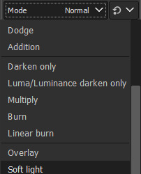
Next, change normal map’s the layer mode to soft light and you’ll have only the details applied to the base texture.
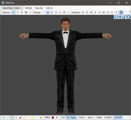
In practice on a model, the base texture is going to change like that. It gives a lot of detail to the model’s face.


Akiyama-san looks more tired than ever.
This technique is extra useful when dealing with clothes so they don’t look horrible. Kiryu-san’s suit looks much better with the improved texture. You can do that to any part that has a normal map, even hair.

3. USEFUL TRICKS
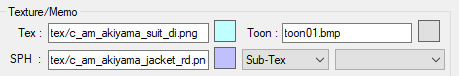
Another texture trick is adding patterns to clothes, like shirt and suit stripes, maybe leather. Let’s call Akiyama-san back to help us with that. This is the default suit texture with normal maps, but it has no stripes! Odd, right? Because his suit has it in the game!


Hi there, Trakinas face!
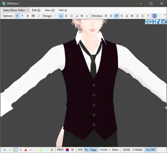
His files come with a pattern for his suit. I picked this texture and added it as a sph sub-tex. Now his suit looks much better, although has no other sph. I tried coming up with a gimmick to work around this, but no success. Better leave it to the shader.


Another example using Kasuga-san’s shirt:


It won’t work all the time though. Also, some patterns will make the part too dark to see anything, so we have to do it the traditional way.
It didn’t work here. The base texture is almost solid black.
So what we do is duplicate the part you want to apply the pattern, add it as a normal texture and change the UV size. It’ll look a little wonky, but that’s the nature of it. You’re always free to try adding it to the texture on GIMP/Photoshop or edit the UV later.

Then make the duplicate part opaque. I usually use 0,3 so it doesn’t interfere a lot. You can keep the sph or not, it’s up to you.

If your game port comes with a texture mapping for shadow and highlights, you can add it to the base texture the same way we did before with the normal maps. I recommend placing the shadow one above the normal.
It helps with shading and creates results closer to the game. Yagami-san looks a lot better with improved textures.

4. CREDITS
Akiyama by lezisell, KS and SEGA
Ichiban by KS and SEGA
Cabaret Kiryu by spooky-majora, KS and SEGA
Lírio by KS
Yagami by Xelandis, KS and SEGA
12 notes
·
View notes
Text
RAY-MMD: custom IES profiles
In this tutorial, you’ll learn how to make custom IES spot lights using the IES2HDR tool. IES lights are useful for simulating lamps, headlights, any man made light source.
Content index:
IES2HDR
Credits
Further Reading
1. IES2HDR
First of all, download this pack of IES profiles for Maya. Don’t worry about all the other things that come with it, we only need the .ies files inside these folders.

Raycast won’t load them as .ies, so we need to convert it to .hdr first. Although fear not, one of Ray’s tools is a script called IES2HDR, which is located inside the Tools folder. Extract that .rar file, make a dummy folder with all the .ies files and drag and drop that dummy folder in the script.
The following screenshots are an illustrated tutorial that comes with IES2HDR:

Once converted, open the Lighting folder and make a copy of the SpotLightIES folder for every IES profile you want to make. Then open it, head to Default and replace the original IES.fx with the new one. Just drag and drop it to rename.


Once finished, load the IES spot light as usual in MMD and load the .fx of any profile you wish to use. Some are pretty different. I didn’t change any morph when picking other profiles.


2. CREDITS
Stage by はまち
IES profiles by Dylan Sisson and updated by Leif Pedersen
3. FURTHER READING
If you wish to learn more about Raycast lightings, I recommend checking out my lighting tutorial, it covers pretty much everything. This side note shall be useful too.
1 note
·
View note
Text
MME Laughing Man FX READING: a translation by ryuu
The following tutorial is an English translation of the original one in Japanese by Dance Intervention P.
Disclaimer: coding isn’t my area, not even close to my actual career and job (writing/health). I have little idea of what’s going on here and I’m relying on my IT friends to help me with this one.
Content index:
Introduction
Overall Flow
Parameter Declaration
Billboard Drawing
Final Notes
1. INTRODUCTION
This documentation shows how to edit the Laughing Man effect and read its HLSL coding. Everything in this tutorial will try to stay as faithful as possible to the original one in Japanese
It was translated from Japanese to English by ryuu. As I don’t know how to contact Dance Intervention P for permission to translate and publish it here, the original author is free to request me to take it down. The translation was done with the aid of the online translator DeepL and my friends’ help. This documentation has no intention in replacing the original author’s.
Any coding line starting with “// [Japanese text]” is the author’s comments. If the coding isn’t properly formatted on Tumblr, you can visit the original document to check it. The original titles of each section were added for ease of use.
2. OVERALL FLOW (全体の流れ)
Prepare a flat polygon that faces the screen (-Z axis) direction.
Perform world rotation and view rotation inversion on objects.
Convert coordinates as usual.
World rotation and view rotation components cancel each other out and always face the screen.
3. PARAMETER DECLARATION (パラメータ宣言)
4 // site-specific transformation matrix
5 float4x4 WorldViewProjMatrix : WORLDVIEWPROJECTION;
6 float4x4 WorldViewMatrixInverse : WORLDVIEWINVERSE;
7
• WorldViewProjMatrix: a matrix that can transform vertices in local coordinates to projective coordinates with the camera as the viewpoint in a single step.
• WorldViewMatrixInverse: the inverse of a matrix that can transform vertices in local coordinates to view coordinates with the camera as the viewpoint in a single step.
• Inverse matrix: when E is the unit matrix for a matrix A whose determinant is non-zero, the matrix B that satisfies AB=BA=E is called the inverse of A and is denoted by A-1 . Because of this property, it’s used to cancel the transformation matrix.
• Unit matrix: asquare matrix whose diagonal component is 1 and the others are 0. When used as a transformation matrix, it means that the coordinates of the vertices are multiplied by 1. In other words:
8 texture MaskTex : ANIMATEDTEXTURE <
9 string ResourceName = "laughing_man.png";
10 >;
• ANIMATEDTEXTURE: textures that animate in response to frame time. Animated GIF and animated PNG (APNG) are supported.
• APNG: Mozilla Corporation's own specified animation format that is backward compatible with PNG. I hacked libpng to support it, but it was rejected by the PNG group because the specification isn’t aesthetically pleasing.
11 sampler Mask = sampler_state {
12 texture = <MaskTex>;
13 MinFilter = LINEAR;
14 MagFilter = LINEAR;
15 MipFilter = NONE;
16 AddressU = CLAMP;
17 AddressV = CLAMP;
18 };
• MinFilter: methods used for the reduction filter.
• MagFilter: methods used for the expansion filter.
• MipFilter: methods used for MIPMAP.
• AdressU: method used to resolve u-texture coordinates that are outside the 0-1 range.
• AdressV: method used to resolve v-texture coordinates that are outside the 0-1 range.
• LINEAR: bilinear interpolation filtering. Uses a weighted average region of 2×2 texels inscribed in the pixel of interest.
• NONE: disable MIPMAP and use the expansion filter.
• CLAMP: texture coordinates outside the range [0.0, 1.0] will have a texture color of 0.0 or 1.0, respectively.
• MIPMAP: a set of images that have been precomputed and optimized to complement the main texture image. Switch between images depending on the level of detail.
21 static float3x3 BillboardMatrix = {
22 normalize(WorldViewMatrixInverse[0].xyz),
23 normalize(WorldViewMatrixInverse[1].xyz),
24 normalize(WorldViewMatrixInverse[2].xyz),
25 };
Obtain the rotation scaling component xyz of the inverse matrix, normalize it by using normalize, and extract the rotation component. Do this for each row. The 4x4 inverse matrix contains a translation component in the fourth row, so it’s cut off and made into a 3x3 matrix.
The logical meaning of the matrix hasn’t been investigated yet. Without normalization, the size of the display accessory is 1/10, which suggests that the world expansion matrix component is used as the unit matrix. Also, each row corresponds to an x,y,z scale.
29 struct VS_OUTPUT
30 {
31 float4 Pos : POSITION; // projective transformation coordinates
32 float2 Tex : TEXCOORD0; // texture coordinates
33 };
A structure for passing multiple return values between shader stages.
4. BILLBOARD DRAWING (ビルボード描画)
35 // vertex shader
36 VS_OUTPUT Mask_VS(float4 Pos : POSITION, float2 Tex : TEXCOORD0)
37 {
38 VS_OUTPUT Out;
39
40 // billboard
41 Pos.xyz = mul( Pos.xyz, BillboardMatrix );
BillboardMatrix is a 3x3 rotation matrix, so multiply it by the xyz3 component of Pos.
If the object is fixed in the world and doesn’t rotate, then Pos.xyz = mul(Pos.xyz, (float3x3)ViewInverseMatrix); or Pos.xyz = mul(Pos.xyz, (float3x3)ViewTransposeMatrix); cancels the screen rotation. Since the rotation matrix is an orthogonal matrix, the transpose and inverse matrices are equal.
42 // world-view projection transformation of camera viewpoint.
43 Out.Pos = mul( Pos, WorldViewProjMatrix );
44
45 // texture coordinates
46 Out.Tex = Tex;
47
48 return Out;
49 }
Perform world-view projection transformation and return the structure as usual.
51 // pixel shader
52 float4 Mask_PS( float2 Tex :TEXCOORD0 ) : COLOR0
53 {
54 return tex2D( Mask, Tex );
55 }
Return the color of the texture retrieved from the sampler.
57 technique MainTec < string MMDPass = "object"; > {
58 pass DrawObject {
59 ZENABLE = false;
60 VertexShader = compile vs_1_1 Mask_VS();
61 PixelShader = compile ps_2_0 Mask_PS();
62 }
63 }
Self-shadow disabled? (technique is ignored by object_ss when enabled), run without depth information.
• ZENABLE: enable seismic intensity information (Z buffer) when drawing pixels and make drawing decisions.
5. FINAL NOTES
For further reading on HLSL coding, please visit Microsoft’s official English reference documentation.
3 notes
·
View notes
Text
RAY-MMD: fixing realistic hair like a king
It took me long to remember writing this tutorial, I’m sorry!
As many know, realistic hair in MMD looks horrible because of how it reads the alpha channels. This makes working with game rips a nightmare depending on the model, but fear not! I’ve been rendering realistic models for so long that fixing fucked up alphas became part of my work.
Also, I’m in no way an expert on the matter, I only do things that don’t demand much from my sanity because honestly? I don’t have energy to waste overworking on hair when Raycast does most of the job for me.
Content Index:
Core Work in PMXe
Alphas in Raycast
Final notes
Credits
1. CORE WORK IN PMXE
If you’re new to fixing game rips, I’m going to cover some basics here of fixing alphas in PMXe and then covering up any flaws later in MMD. Notice that this tutorial is aimed toward the realistic models for our quality of life!
First things first. This tutorial’s guest is Hoshino-san! He’s going to help me illustrate the alpha fixing, as I haven’t worked on his model yet.

Good to see you, Hoshino-san!
As you can see, his hair looks like shit, but that’s an easy fix. A common and straight forward cut like that one won’t take long. Messy hair like Yagami’s can be hell on earth, so it’s best to do fix some parts here and there, then leave it to Ray.

I hate you (affectionate).

Raw hair from his untouched topless model. I’m so sorry, Yagami-san...
Now back to Hoshino-san, a good way of dealing with it is by separating the hair meshes with the UV plug-in. If you’re new to this, I’ll show you step by step how to open it.

Now running the plug-in, look for the hair mesh on the material list. The hair must always be at the end of the mesh order for alpha priority. That’s what happens when otherwise.

Back to the plug-in, I found our hair mesh. What we’ll do is to select vertical parts of it and hit Show Selected Vertices to split them. Don’t forget to select the material and make the vertices visible before doing so.


After splitting, hit Re-Import Model Data to refresh the plug-in and update the materials. Now you split the other major meshes until PMXe “refuses” to go further. Sometimes, you’ll be done by then, but that wasn’t Hoshino-san’s case.

He looks better, but still need fixing. We can close the UV plug-in and proceed to manually select and split meshes using face and triangle selections. You can active or not the wireframe for ease of use, it’s personal preference.
We’ll click on desired mesh and hit CTRL + X to select every mesh linked to the one you picked. Be aware that this doesn’t work on every model, some simply can’t do it for whatever reason (I’m not a PMXe expert).

This is a tedious process, you have to keep checking and rearranging the meshes. If you want superb results, good for you! Expect spending a lot of time on this. I did the bare minimum and Hoshino-san looks much better now.
Now you save updated model and go have fun!

2. ALPHAS IN RAYCAST
“But Lírio, what if I want to have fun in MMD and my model’s hair looks like puke when I load Raycast?”, one may think. Ray sucks for any transparent material, simple as that. Of course you can work around it using the transparent material, but the results aren’t that predictable if you ask me. While it looks awesome for tears and glasses, you can’t use this material on hair.
For any alpha fix, we use dendewa’s material. It’s easy to set up and we’ll go step by step. Before anything, I want to show you how hair looks if you load main.fx and leave it be.

Fucked, right?
It doesn’t get any better when we load main_ex_mask.fx...

So our solution is to use the alpha material. To make it work, first load main_alpha.fx on the hair and any other transparent part. It’s located in the Alpha Fix folder.

Now go to the MaterialMap tab and select any material from the Hair Materials folder. I like picking hair with anisotropy 3x for the shiny look or hair with SSS.


Anisotropy 3x.

SSS.
Hoshino-san looks great! However, some hair details are missing. The same happens to eyelashes, they disappear. How we work around this? We add Croquis! Just change the Z value to 1 and it’ll read the textures for you. Setting X and Y values to 1 grant more edges.
While it isn’t the ideal, it works fine. Don’t worry about this effect killing the 3D aspect of your renders. You can always change the Tr and Si to a smaller value.

3. FINAL NOTES
In other scenarios, Croquis is a must to save the model’s hair with Ray. Unfortunately, you’ll have to deal with black edges around the hair. The tons of effects that a render has will probably hide or make them less obvious.

Raw alpha fix.

Tr 1.

Tr 0.5.
Do you remember Yagami-san’s hair from before? That’s him now! It isn’t perfect, but does the job just fine. In his case, X was needed to cover the smallest hair strands. The first image shows X, Y and Z on 1 and Si on 0.5; the second, Si 1.


4. CREDITS
Connor by Quantic Dream
Yagami and Hoshino by SEGA
7 notes
·
View notes
Text
Additions regarding Ray lights
I’d like to add some things related to this post about Raycast lighting. I’ll be brief. Following my two most recent renders as of today, 09/05/21, I tried out some new things with volumetric fog, skydome and spot lights.
Content index
Skydome
Volumetric Fog
Spot Light
Credits
1. SKYDOME
If you’ve read my advanced image rendering guide, I mention using dendewa’s Blank IBL skydome for lighting. However, I’ve encountered some issues with it (and again, it’s only a matter of personal taste) regarding how materials behave when this one is loaded and the stronger shadows too.
A much “safer” and neutral option I found was loading Sky Hemisphere. This skydome is basic and offers softer lighting when you load its .fx, making lighting easier to adjust.
To clarify this difference, I asked Daigo-san to help me out! The first image features Sky Hemisphere, while the second, Blank IBL. The hair has anisotropy 3x for the highlights, a shiny look.


Can you notice the huge difference between them? The shadows are much stronger with Blank IBL, they’re harsh on the model. On the other hand, Sky Hemisphere features soft shading with visible shadows. Plus the hair isn’t a black mass with little shiny spots. This “washed out” appearance can be fixed with materials and increased contrast.
My general advice is: you don’t know what you’re doing? Stick to Sky Hemisphere instead of Blank IBL. Dendewa recommends the latter for custom physical lights. I, ryuu, say for myself that Sky Hemisphere is great for that, better even. My renders with Sky Hemisphere had much satisfying results.
2. VOLUMETRIC FOG
Volumetric fogs, either cube or sphere, can be used to darken the scene without messing with skydome properties. It’s a good tweak that can be improved with Ray’s controller by changing the exposure and gamma. I didn’t notice good enough results when decreasing the sunlight, but that’s a matter of personal taste and technique.
To tweak the volumetric fog like that, you can max out the width, height and depth, and increase the intensity until it’s good enough for your project. Then you play with light and everything else. It’ll look like this when raw.

It isn’t much, but already helps!
The render below was darkened with a volumetric cube. I’ll provide both raw and retouched versions for you to see it wasn’t darkened in post-editing.


Tube lights were good for some hair higlighting, but I wouldn’t do it again, as it was kind of annoying to set up.
3. SPOT LIGHT
Spot lights proved to be a solid pick for general lighting for having the best shadow quality of all of the available lights. The lit area is easily adjusted by increasing the angle. When adding the shadow .fx, it looks incredibly good on realistic hair for shading.

The render below was made using spot lights and a directional light. Raw and post-edited versions included.


I’ll later write a tutorial about color theory applied to MMD and how it can improve your rendering. I did my homework and studied some of it!
4. CREDITS
Daigo, Majima and Yagami by SEGA
Heart Sunglasses by 1010
3 notes
·
View notes
Text
MMD FX file reading for shaders: a translation by ryuu
The following tutorial is an English translation of the original one in Japanese by Dance Intervention P.
This English documentation was requested by Chestnutscoop on DeviantArt, as it’ll be useful to the MME modding community and help MMD become open-source for updates. It’s going to be an extensive one, so take it easy.
Disclaimer: coding isn’t my area, not even close to my actual career and job (writing/health). I have little idea of what’s going on here and I’m relying on my IT friends to help me with this one.
Content Index:
Introduction
Overall Flow
Parameter Declaration
Outline Drawing
Non-Self-shadow Rendering
Drawing Objects When Self-shadow is Disabled
Z-value Plot For Self-shadow Determination
Drawing Objects in Self-shadowing
Final Notes
1. INTRODUCTION
This documentation contains the roots of .fx file reading for MME as well as information on DirectX and programmable shaders while reading full.fx version 1.3. In other words, how to use HLSL for MMD shaders. Everything in this tutorial will try to stay as faithful as possible to the original text in Japanese.
It was translated from Japanese to English by ryuu. As I don’t know how to contact Dance Intervention P for permission to translate and publish it here, the original author is free to request me to take it down. The translation was done with the aid of the online translator DeepL and my friends’ help. This documentation has no intention in replacing the original author’s.
Any coding line starting with “// [Japanese text]” is the author’s comments. If the coding isn’t properly formatted on Tumblr, you can visit the original document to check it. The original titles of each section were added for ease of use.
2. OVERALL FLOW (全体の流れ)
Applicable technique → pass → VertexShader → PixelShader
• Technique: processing of annotations that fall under <>.
• Pass: processing unit.
• VertexShader: convert vertices in local coordinates to projective coordinates.
• PixelShader: sets the color of a vertex.
3. PARAMETER DECLARATION (パラメータ宣言)
9 // site-specific transformation matrix
10 float4x4 WorldViewProjMatrix : WORLDVIEWPROJECTION;
11 float4x4 WorldMatrix : WORLD;
12 float4x4 ViewMatrix : VIEW;
13 float4x4 LightWorldViewProjMatrix : WORLDVIEWPROJECTION < string Object = “Light”; >;
• Float4x4: 32-bit floating point with 4 rows and 4 columns.
• WorldViewProjMatrix: a matrix that can transform vertices in local coordinates to projective coordinates with the camera as the viewpoint in a single step.
• WorldMatrix: a matrix that can transform vertices in local coordinates into world coordinates with the camera as the viewpoint.
• ViewMatrix: a matrix that can convert world coordinate vertices to view coordinates with the camera as the viewpoint.
• LightWorldViewProjMatrix: a matrix that can transform vertices in local coordinates to projective coordinates with the light as a viewpoint in a single step.
• Local coordinate system: coordinates to represent the positional relationship of vertices in the model.
• World coordinate: coordinates to show the positional relationship between models.
• View coordinate: coordinates to represent the positional relationship with the camera.
• Projection Coordinates: coordinates used to represent the depth in the camera. There are two types: perspective projection and orthographic projection.
• Perspective projection: distant objects are shown smaller and nearby objects are shown larger.
• Orthographic projection: the size of the image does not change with depth.
15 float3 LightDirection : DIRECTION < string Object = “Light”; >;
16 float3 CameraPosition : POSITION < string Object = “Camera”; >;
• LightDirection: light direction vector.
• CameraPosition: world coordinates of the camera.
18 // material color
19 float4 MaterialDiffuse : DIFFUSE < string Object = “Geometry”; >;
20 float3 MaterialAmbient : AMBIENT < string Object = “Geometry”; >;
21 float3 MaterialEmmisive : EMISSIVE < string Object = “Geometry”; >;
22 float3 MaterialSpecular : SPECULAR < string Object = “Geometry”; >;
23 float SpecularPower : SPECULARPOWER < string Object = “Geometry”; >;
24 float3 MaterialToon : TOONCOLOR;
25 float4 EdgeColor : EDGECOLOR;
• float3: no alpha value.
• MaterialDiffuse: diffuse light color of material, Diffuse+A (alpha value) in PMD.
• MaterialAmbient: ambient light color of the material; Diffuse of PMD?
• MaterialEmmisive: light emitting color of the material, Ambient in PMD.
• MaterialSpecular: specular light color of the material; PMD’s Specular.
• SpecularPower: specular strength. PMD Shininess.
• MaterialToon: shade toon color of the material, lower left corner of the one specified by the PMD toon texture.
• EdgeColor: putline color, as specified by MMD’s edge color.
26 // light color
27 float3 LightDiffuse : DIFFUSE < string Object = “Light”; >;
28 float3 LightAmbient : AMBIENT < string Object = “Light”; >;
29 float3 LightSpecular : SPECULAR < string Object = “Light”; >;
30 static float4 DiffuseColor = MaterialDiffuse * float4(LightDiffuse, 1.0f);
31 static float3 AmbientColor = saturate(MaterialAmbient * LightAmbient + MaterialEmmisive);
32 static float3 SpecularColor = MaterialSpecular * LightSpecular;
• LightDiffuse: black (floa3(0,0,0))?
• LightAmbient: MMD lighting operation values.
• LightSpecular: MMD lighting operation values.
• DiffuseColor: black by multiplication in LightDiffuse?
• AmbientColor: does the common color of Diffuse in PMD become a little stronger in the value of lighting manipulation in MMD?
• SpecularColor: does it feel like PMD’s Specular is a little stronger than MMD’s Lighting Manipulation value?
34 bool parthf; // perspective flags
35 bool transp; // semi-transparent flag
36 bool spadd; // sphere map additive synthesis flag
37 #define SKII1 1500
38 #define SKII2 8000
39 #define Toon 3
• parthf: true for self-shadow distance setting mode2.
• transp: true for self-shadow distance setting mode2.
• spadd: true in sphere file .spa.
• SKII1:self-shadow A constant used in mode1. The larger the value, the weirder the shadow will be, and the smaller the value, the weaker the shadow will be.
• SKII2: self-shadow A constant used in mode2. If it is too large, the self-shadow will have a strange shadow, and if it is too small, it will be too thin.
• Toon: weaken the shade in the direction of the light with a close range shade toon.
41 // object textures
42 texture ObjectTexture: MATERIALTEXTURE;
43 sampler ObjTexSampler = sampler_state {
44 texture = <ObjectTexture>;
45 MINFILTER = LINEAR;
46 MAGFILTER = LINEAR;
47 };
48
• ObjectTexture: texture set in the material.
• ObjTexSampler: setting the conditions for acquiring material textures.
• MINIFILTER: conditions for shrinking textures.
• MAGFILTER: conditions for enlarging a texture.
• LINEAR: interpolate to linear.
49 // sphere map textures
50 texture ObjectSphereMap: MATERIALSPHEREMAP;
51 sampler ObjSphareSampler = sampler_state {
52 texture = <ObjectSphereMap>;
53 MINFILTER = LINEAR;
54 MAGFILTER = LINEAR;
55 };
• ObjectSphereMap: sphere map texture set in the material.
• ObjSphareSampler: setting the conditions for obtaining a sphere map texture.
57 // this is a description to avoid overwriting the original MMD sampler. Cannot be deleted.
58 sampler MMDSamp0 : register(s0);
59 sampler MMDSamp1 : register(s1);
60 sampler MMDSamp2 : register(s2);
• register: assign shader variables to specific registers.
• s0: sampler type register 0.
4. OUTLINE DRAWING (輪郭描画)
Model contours used for drawing, no accessories.
65 // vertex shader
66 float4 ColorRender_VS(float4 Pos : POSITION) : POSITION
67 {
68 // world-view projection transformation of camera viewpoint.
69 return mul( Pos, WorldViewProjMatrix );
70 }
Return the vertex coordinates of the camera viewpoint after the world view projection transformation.
Parameters
• Pos: local coordinates of the vertex.
• POSITION (input): semantic indicating the vertex position in the object space.
• POSITION (output): semantic indicating the position of a vertex in a homogeneous space.
• mul (x,y): perform matrix multiplication of x and y.
Return value
Vertex coordinates in projective space; compute screen coordinate position by dividing by w.
• Semantics: communicating information about the intended use of parameters.
72 // pixel shader
73 float4 ColorRender_PS() : COLOR
74 {
75 // fill with outline color
76 return EdgeColor;
77 }
Returns the contour color of the corresponding input vertex.
Return value
Output color
• COLOR: output color semantic.
79 // contouring techniques
80 technique EdgeTec < string MMDPass = "edge"; > {
81 pass DrawEdge {
82 AlphaBlendEnable = FALSE;
83 AlphaTestEnable = FALSE;
84
85 VertexShader = compile vs_2_0 ColorRender_VS();
86 PixelShader = compile ps_2_0 ColorRender_PS();
87 }
88 }
Processing for contour drawing.
• MMDPASS: specify the drawing target to apply.
• “edge”: contours of the PMD model.
• AlphaBlendEnable: set the value to enable alpha blending transparency. Blend surface colors, materials, and textures with transparency information to overlay on another surface.
• AlphaTestEnable: per-pixel alpha test setting. If passed, the pixel will be processed by the framebuffer. Otherwise, all framebuffer processing of pixels will be skipped.
• VertexShader: shader variable representing the compiled vertex shader.
• PixelShader: shader variable representing the compiled pixel shader.
• vs_2_0: vertex shader profile for shader model 2.
• ps_2_0: pixel shader profile for shader model 2.
• Frame buffer: memory that holds the data for one frame until it is displayed on the screen.
5. NON-SELF-SHADOW SHADOW RENDERING (非セルフシャドウ影描画)
Drawing shadows falling on the ground in MMD, switching between showing and hiding them in MMD's ground shadow display.
94 // vertex shader
95 float4 Shadow_VS(float4 Pos : POSITION) : POSITION
96 {
97 // world-view projection transformation of camera viewpoint.
98 return mul( Pos, WorldViewProjMatrix );
99 }
Returns the vertex coordinates of the source vertex of the shadow display after the world-view projection transformation of the camera viewpoint.
Parameters
• Pos: local coordinates of the vertex from which the shadow will be displayed.
Return value
Vertex coordinates in projective space.
101 // pixel shader
102 float4 Shadow_PS() : COLOR
103 {
104 // fill with ambient color
105 return float4(AmbientColor.rgb, 0.65f);
106 }
Returns the shadow color to be drawn. The alpha value will be reflected when MMD's display shadow color transparency is enabled.
Return value
Output color
108 // techniques for shadow drawing
109 technique ShadowTec < string MMDPass = "shadow"; > {
110 pass DrawShadow {
111 VertexShader = compile vs_2_0 Shadow_VS();
112 PixelShader = compile ps_2_0 Shadow_PS();
113 }
114 }
Processing for non-self-shadow shadow drawing.
• “shadow”: simple ground shadow.
6. DRAWING OBJECTS WHEN SELF-SHADOW IS DISABLED (セルフシャドウ無効時オブジェクト描画)
Drawing objects when self-shadowing is disabled. Also used when editing model values.
120 struct VS_OUTPUT {
121 float4 Pos : POSITION; // projective transformation coordinates
122 float2 Tex : TEXCOORD1; // texture
123 float3 Normal : TEXCOORD2; // normal vector
124 float3 Eye : TEXCOORD3; // position relative to camera
125 float2 SpTex : TEXCOORD4; // sphere map texture coordinates
126 float4 Color : COLOR0; // diffuse color
127 };
A structure for passing multiple return values between shader stages. The final data to be passed must specify semantics.
Parameters
• Pos:stores the position of a vertex in projective coordinates as a homogeneous spatial coordinate vertex shader output semantic.
• Tex: stores the UV coordinates of the vertex as the first texture coordinate vertex shader output semantic.
• Normal: stores the vertex normal vector as the second texture coordinate vertex shader output semantic.
• Eye: (opposite?) stores the eye vector as a #3 texture coordinate vertex shader output semantic.
• SpTex: stores the UV coordinates of the vertex as the number 4 texture coordinate vertex shader output semantic.
• Color: stores the diffuse light color of a vertex as the 0th color vertex shader output semantic.
129 // vertex shader
130 VS_OUTPUT Basic_VS(float4 Pos : POSITION, float3 Normal : NORMAL, float2 Tex : TEXCOORD0, uniform bool useTexture, uniform bool useSphereMap, uniform bool useToon)
131 {
Converts local coordinates of vertices to projective coordinates. Sets the value to pass to the pixel shader, which returns the VS_OUTPUT structure.
Parameters
• Pos: local coordinates of the vertex.
• Normal: normals in local coordinates of vertices.
• Tex: UV coordinates of the vertices.
• useTexture: determination of texture usage, given by pass.
• useSphereMap: determination of sphere map usage, given by pass.
• useToon: determination of toon usage. Given by pass in the case of model data.
• uniform: marks variables with data that are always constant during shader execution.
Return value
VS_OUTPUT, a structure passed to the pixel shader.
132 VS_OUTPUT Out = (VS_OUTPUT)0;
133
Initialize structure members with 0. Error if return member is undefined.
134 // world-view projection transformation of camera viewpoint.
135 Out.Pos = mul( Pos, WorldViewProjMatrix );
136
Convert local coordinates of vertices to projective coordinates.
137 // position relative to camera
138 Out.Eye = CameraPosition - mul( Pos, WorldMatrix );
The opposite vector of eye? Calculate.
139 // vertex normal
140 Out.Normal = normalize( mul( Normal, (float3x3)WorldMatrix ) );
141
Compute normalized normal vectors in the vertex world space.
• normalize (x): normalize a floating-point vector based on x/length(x).
• length (x): returns the length of a floating-point number vector.
142 // Diffuse color + Ambient color calculation
143 Out.Color.rgb = AmbientColor;
144 if ( !useToon ) {
145 Out.Color.rgb += max(0,dot( Out.Normal, -LightDirection )) * DiffuseColor.rgb;
By the inner product of the vertex normal and the backward vector of the light, the influence of the light (0-1) is calculated, and the diffuse light color calculated from the influence is added to the ambient light color. DiffuseColor is black because LightDifuse is black, and AmbientColor is the diffuse light of the material. Confirmation required.
• dot (x,y): return the inner value of the x and y vectors.
• max (x,y): choose the value of x or y, whichever is greater.
146 }
147 Out.Color.a = DiffuseColor.a;
148 Out.Color = saturate( Out.Color );
149
• saturate (x): clamp x to the range 0-1. 0>x, 1>x truncated?
150 // texture coordinates
151 Out.Tex = Tex;
152
153 if ( useSphereMap ) {
154 // sphere map texture coordinates
155 float2 NormalWV = mul( Out.Normal, (float3x3)ViewMatrix );
X and Y coordinates of vertex normals in view space.
156 Out.SpTex.x = NormalWV.x * 0.5f + 0.5f;
157 Out.SpTex.y = NormalWV.y * -0.5f + 0.5f;
158 }
159
Converts view coordinate values of vertex normals to texture coordinate values. Idiomatic.
160 return Out;
161 }
Return the structure you set.
163 // pixel shader
164 float4 Basic_PS(VS_OUTPUT IN, uniform bool useTexture, uniform bool useSphereMap, uniform bool useToon) : COLOR0
165 {
Specify the color of pixels to be displayed on the screen.
Parameters
• IN: VS_OUTPUT structure received from the vertex shader.
• useTexture: determination of texture usage, given by pass.
• useSphereMap: determination of using sphere map, given by pass.
• useToon: determination of toon usage. Given by pass in the case of model data.
Output value
Output color
166 // specular color calculation
167 float3 HalfVector = normalize( normalize(IN.Eye) + -LightDirection );
Find the half vector from the inverse vector of the line of sight and the inverse vector of the light.
• Half vector: a vector that is the middle (addition) of two vectors. Used instead of calculating the reflection vector.
168 float3 Specular = pow( max(0,dot( HalfVector, normalize(IN.Normal) )), SpecularPower ) * SpecularColor;
169
From the half-vector and vertex normals, find the influence of reflection. Multiply the influence by the specular intensity, and multiply by the specular light color to get the specular.
• pow (x,y): multiply x by the exponent y.
170 float4 Color = IN.Color;
171 if ( useTexture ) {
172 // apply texture
173 Color *= tex2D( ObjTexSampler, IN.Tex );
174 }
If a texture is set, extract the color of the texture coordinates and multiply it by the base color.
• tex2D (sampler, tex): extract the color of the tex coordinates from the 2D texture in the sampler settings.
175 if ( useSphereMap ) {
176 // apply sphere map
177 if(spadd) Color += tex2D(ObjSphareSampler,IN.SpTex);
178 else Color *= tex2D(ObjSphareSampler,IN.SpTex);
179 }
180
If a sphere map is set, extract the color of the sphere map texture coordinates and add it to the base color if it is an additive sphere map file, otherwise multiply it.
181 if ( useToon ) {
182 // toon application
183 float LightNormal = dot( IN.Normal, -LightDirection );
184 Color.rgb *= lerp(MaterialToon, float3(1,1,1), saturate(LightNormal * 16 + 0.5));
185 }
In the case of the PMD model, determine the influence of the light from the normal vector of the vertex and the inverse vector of the light. Correct the influence level to 0.5-1, and darken the base color for lower influence levels.
• lerp (x,y,s): linear interpolation based on x + s(y - x). 0=x, 1=y.
186
187 // specular application
188 Color.rgb += Specular;
189
190 return Color;
191 }
Add the obtained specular to the base color and return the output color.
195 technique MainTec0 < string MMDPass = "object"; bool UseTexture = false; bool UseSphereMap = false; bool UseToon = false; > {
196 pass DrawObject {
197 VertexShader = compile vs_2_0 Basic_VS(false, false, false);
198 PixelShader = compile ps_2_0 Basic_PS(false, false, false);
199 }
200 }
Technique performed on a subset of accessories (materials) that don’t use texture or sphere maps when self-shadow is disabled.
• “object”: object when self-shadow is disabled.
• UseTexture: true for texture usage subset.
• UseSphereMap: true for sphere map usage subset.
• UseToon: true for PMD model.
7. Z-VALUE PLOT FOR SELF-SHADOW DETERMINATION (セルフシャドウ判定用Z値プロット)
Create a boundary value to be used for determining the self-shadow.
256 struct VS_ZValuePlot_OUTPUT {
257 float4 Pos : POSITION; // projective transformation coordinates
258 float4 ShadowMapTex : TEXCOORD0; // z-buffer texture
259 };
A structure for passing multiple return values between shader stages.
Parameters
• Pos: stores the position of a vertex in projective coordinates as a homogeneous spatial coordinate vertex shader output semantic.
• ShadowMapTex: stores texture coordinates for hardware calculation of z and w interpolation values as 0 texture coordinate vertex shader output semantics.
• w: scaling factor of the visual cone (which expands as you go deeper) in projective space.
261 // vertex shader
262 VS_ZValuePlot_OUTPUT ZValuePlot_VS( float4 Pos : POSITION )
263 {
264 VS_ZValuePlot_OUTPUT Out = (VS_ZValuePlot_OUTPUT)0;
265
266 // do a world-view projection transformation with the eyes of the light.
267 Out.Pos = mul( Pos, LightWorldViewProjMatrix );
268
Conversion of local coordinates of a vertex to projective coordinates with respect to a light.
269 // align texture coordinates to vertices.
270 Out.ShadowMapTex = Out.Pos;
271
272 return Out;
273 }
Assign to texture coordinates to let the hardware calculate z, w interpolation values for vertex coordinates, and return the structure.
275 // pixel shader
276 float4 ZValuePlot_PS( float4 ShadowMapTex : TEXCOORD0 ) : COLOR
277 {
278 // record z-values for R color components
279 return float4(ShadowMapTex.z/ShadowMapTex.w,0,0,1);
280 }
Divide the z-value in projective space by the magnification factor w, calculate the z-value in screen coordinates, assign to r-value and return (internal MMD processing?).
282 // techniques for Z-value mapping
283 technique ZplotTec < string MMDPass = "zplot"; > {
284 pass ZValuePlot {
285 AlphaBlendEnable = FALSE;
286 VertexShader = compile vs_2_0 ZValuePlot_VS();
287 PixelShader = compile ps_2_0 ZValuePlot_PS();
288 }
289 }
Technique to be performed when calculating the z-value for self-shadow determination.
• “zplot”: Z-value plot for self-shadow.
8. DRAWING OBJECTS IN SELF-SHADOWING (セルフシャドウ時オブジェクト描画)
Drawing an object with self-shadow.
295 // sampler for the shadow buffer. “register(s0)" because MMD uses s0
296 sampler DefSampler : register(s0);
297
Assign sampler register 0 to DefSampler. Not sure when it’s swapped with MMDSamp0 earlier. Not replaceable.
298 struct BufferShadow_OUTPUT {
299 float4 Pos : POSITION; // projective transformation coordinates
300 float4 ZCalcTex : TEXCOORD0; // z value
301 float2 Tex : TEXCOORD1; // texture
302 float3 Normal : TEXCOORD2; // normal vector
303 float3 Eye : TEXCOORD3; // position relative to camera
304 float2 SpTex : TEXCOORD4; // sphere map texture coordinates
305 float4 Color : COLOR0; // diffuse color
306 };
VS_OUTPUT with ZCalcTex added.
• ZCalcTex: stores the texture coordinates for calculating the interpolation values of Z and w for vertices in screen coordinates as the 0 texture coordinate vertex shader output semantic.
308 // vertex shader
309 BufferShadow_OUTPUT BufferShadow_VS(float4 Pos : POSITION, float3 Normal : NORMAL, float2 Tex : TEXCOORD0, uniform bool useTexture, uniform bool useSphereMap, uniform bool useToon)
310 {
Converts local coordinates of vertices to projective coordinates. Set the value to pass to the pixel shader, returning the BufferShadow_OUTPUT structure.
Parameters
• Pos: local coordinates of the vertex.
• Normal: normals in local coordinates of vertices.
• Tex: UV coordinates of the vertices.
• useTexture: determination of texture usage, given by pass.
• useSphereMap: determination of sphere map usage, given by pass.
• useToon: determination of toon usage. Given by pass in the case of model data.
Return value
BufferShadow_OUTPUT.
311 BufferShadow_OUTPUT Out = (BufferShadow_OUTPUT)0;
312
Initializing the structure.
313 // world-view projection transformation of camera viewpoint.
314 Out.Pos = mul( Pos, WorldViewProjMatrix );
315
Convert local coordinates of vertices to projective coordinates.
316 // position relative to camera 317 Out.Eye = CameraPosition - mul( Pos, WorldMatrix );
Calculate the inverse vector of the line of sight.
318 // vertex normal
319 Out.Normal = normalize( mul( Normal, (float3x3)WorldMatrix ) );
Compute normalized normal vectors in the vertex world space.
320 // world View Projection Transformation with Light Perspective
321 Out.ZCalcTex = mul( Pos, LightWorldViewProjMatrix );
Convert local coordinates of vertices to projective coordinates with respect to the light, and let the hardware calculate z and w interpolation values.
323 // Diffuse color + Ambient color Calculation
324 Out.Color.rgb = AmbientColor;
325 if ( !useToon ) {
326 Out.Color.rgb += max(0,dot( Out.Normal, -LightDirection )) * DiffuseColor.rgb;
327 }
328 Out.Color.a = DiffuseColor.a;
329 Out.Color = saturate( Out.Color );
Set the base color. For accessories, add a diffuse color to the base color based on the light influence, and set each component to 0-1.
331 // texture coordinates
332 Out.Tex = Tex;
Assign the UV coordinates of the vertex as they are.
334 if ( useSphereMap ) {
335 // sphere map texture coordinates
336 float2 NormalWV = mul( Out.Normal, (float3x3)ViewMatrix );
Convert vertex normal vectors to x and y components in view space coordinates when using sphere maps.
337 Out.SpTex.x = NormalWV.x * 0.5f + 0.5f;
338 Out.SpTex.y = NormalWV.y * -0.5f + 0.5f;
339 }
340
341 return Out;
342 }
Convert view space coordinates to texture coordinates and put the structure back.
344 // pixel shader
345 float4 BufferShadow_PS(BufferShadow_OUTPUT IN, uniform bool useTexture, uniform bool useSphereMap, uniform bool useToon) : COLOR
346 {
Specify the color of pixels to be displayed on the screen.
Parameters
• IN: BufferShadow_OUTPUT structure received from vertex shader.
• useTexture: determination of texture usage, given by pass.
• useSphereMap: determination of sphere map usage, given by pass.
• useToon: determination of toon usage. Given by pass in the case of model data.
Output value
Output color
347 // specular color calculation
348 float3 HalfVector = normalize( normalize(IN.Eye) + -LightDirection );
349 float3 Specular = pow( max(0,dot( HalfVector, normalize(IN.Normal) )), SpecularPower ) * SpecularColor;
350
Same specular calculation as Basic_PS.
351 float4 Color = IN.Color;
352 float4 ShadowColor = float4(AmbientColor, Color.a); // shadow’s color
Base color and self-shadow base color.
353 if ( useTexture ) {
354 // apply texture
355 float4 TexColor = tex2D( ObjTexSampler, IN.Tex );
356 Color *= TexColor;
357 ShadowColor *= TexColor;
358 }
When using a texture, extract the color of the texture coordinates from the set texture and multiply it by the base color and self-shadow color respectively.
359 if ( useSphereMap ) {
360 // apply sphere map
361 float4 TexColor = tex2D(ObjSphareSampler,IN.SpTex);
362 if(spadd) {
363 Color += TexColor;
364 ShadowColor += TexColor;
365 } else {
366 Color *= TexColor;
367 ShadowColor *= TexColor;
368 }
369 }
As with Basic_PS, when using a sphere map, add or multiply the corresponding colors.
370 // specular application
371 Color.rgb += Specular;
372
Apply specular to the base color.
373 // convert to texture coordinates 374 IN.ZCalcTex /= IN.ZCalcTex.w;
Divide the z-value in projective space by the scaling factor w and convert to screen coordinates.
375 float2 TransTexCoord;
376 TransTexCoord.x = (1.0f + IN.ZCalcTex.x)*0.5f;
377 TransTexCoord.y = (1.0f - IN.ZCalcTex.y)*0.5f;
378
Convert screen coordinates to texture coordinates.
379 if( any( saturate(TransTexCoord) != TransTexCoord ) ) {
380 // external shadow buffer
381 return Color;
Return the base color if the vertex coordinates aren’t in the 0-1 range of the texture coordinates.
382 } else {
383 float comp;
384 if(parthf) {
385 // self-shadow mode2
386 comp=1-saturate(max(IN.ZCalcTex.z-tex2D(DefSampler,TransTexCoord).r , 0.0f)*SKII2*TransTexCoord.y-0.3f);
In self-shadow mode2, take the Z value from the shadow buffer sampler and compare it with the Z value of the vertex, if the Z of the vertex is small, it isn't a shadow. If the difference is small (close to the beginning of the shadow), the shadow is heavily corrected. (Weak correction in the upward direction of the screen?) Weakly corrects the base color.
387 } else {
388 // self-shadow mode1
389 comp=1-saturate(max(IN.ZCalcTex.z-tex2D(DefSampler,TransTexCoord).r , 0.0f)*SKII1-0.3f);
390 }
Do the same for self-shadow mode1.
391 if ( useToon ) {
392 // toon application
393 comp = min(saturate(dot(IN.Normal,-LightDirection)*Toon),comp);
In the case of MMD models, compare the degree of influence of the shade caused by the light with the degree of influence caused by the self-shadow, and choose the smaller one as the degree of influence of the shadow.
• min (x,y): select the smaller value of x and y.
394 ShadowColor.rgb *= MaterialToon;
395 }
396
Multiply the self-shadow color by the toon shadow color.
397 float4 ans = lerp(ShadowColor, Color, comp);
Linearly interpolate between the self-shadow color and the base color depending on the influence of the shadow.
398 if( transp ) ans.a = 0.5f;
399 return ans;
400 }
401 }
If translucency is enabled, set the transparency of the display color to 50% and restore the composite color.
403 // techniques for drawing objects (for accessories)
404 technique MainTecBS0 < string MMDPass = "object_ss"; bool UseTexture = false; bool UseSphereMap = false; bool UseToon = false; > {
405 pass DrawObject {
406 VertexShader = compile vs_3_0 BufferShadow_VS(false, false, false);
407 PixelShader = compile ps_3_0 BufferShadow_PS(false, false, false);
408 }
409 }
Technique performed on a subset of accessories (materials) that don’t use a texture or sphere map during self-shadowing.
• “object-ss”: object when self-shadow is disabled.
• UseTexture: true for texture usage subset.
• UseSphereMap: true for sphere map usage subset.
• UseToon: true for PMD model.
9. FINAL NOTES
For further reading on HLSL coding, please visit Microsoft’s official English reference documentation.
5 notes
·
View notes
Text
RAY-MMD lighting tips: a translation by ryuu
The following tutorial is an English translation of the original one in Japanese by ngreeed. (WARNING: the website is NSFW)
Let’s get started? If you just landed on this tutorial for advanced MMDers and is wondering what the hell is going on, there are beginner Raycast tutorials in Learn MMD! Also, if you feel like reading more about rendering tips, I suggest taking a look at my other tutorial: advanced MMD rendering tutorial (and why you should care).
Content Index:
Introduction
Lighting: introduction
Lighting: basics
Fog
Other Tips
Final Notes
Introduction to Lighting Content Index:
Directional Light
Rectangle Light
Sphere Light
Point Light
Spot Light
Spot Light IES
Disk Light
Tube Light
Basics of Lighting Content Index:
Ambient
Shadow
Fog
IES
LED
IBL
GIF
Fog Content Index:
Atmospheric Fog
Ground Fog
Volumetric Cube And Sphere
1. INTRODUCTION
This compilation was brought together by the MMD community and contemplates ngreeed’s own experiences with fog and lighting usages. Every picture shown in this translation can be found in the original documentations on Iwara and GitHub.
It was translated from Japanese to English by ryuu with written permission from the author to share it on my blog and add information. The translation was done with the aid of the online translator DeepL and my friends’ help. This tutorial has no intention in replacing the original author’s.
2. LIGHTING: INTRODUCTION
By learning lighting, you’ll have more freedom in directing your videos, but it’s only for those who are confident that they understand how to use Ray-mmd, because it’s a pre-requisite and an additional part of understanding how to use skybox and materials. If you’re unsure about the other two items, start by reading this wiki.
Originally, surface lights in a 3DCG software are characterized by their ability to create soft shadows, but the surface lights used in Ray-MMD are very difficult to handle and don’t provide much benefit, so we recommend using point lights or directional lights.
Translator’s note: for those wondering what lights are available in Raycast, there’s a translation below of the wiki’s list.
2.1 Directional Light
Directional light simulates lighting hitting an object from an infinite distance. The angle of each ray reaching the object is negligible and the rays will always be parallel to each other, so it is also called sunlight.
Directional light doesn’t take into account the coordinates of the light source and won’t affect the lighting effect when placed in any position of the scene. Only the rotation will affect the lighting, because of the nature of directional light requires shading calculations for the whole scene.
Therefore its computational overhead is the largest among all multi-source shadows, and its shadow quality is only suitable for lighting characters at very high quality, which you may use when you want to attach a bone to the main light source.
2.2 Rectangle Light
The light source will shine from a plane towards a fixed range. It’s used to simulate monitors, screens, smartphones, etc.
Since the light source of the area light needs to consider the volume of the light source, the real calculation of its shadow in real time is very difficult to do. It’s recommended to use spot light shadow instead.

2.3 Sphere Light
The light is emitted from the location of the light source to the surrounding area and the volume of the light source is taken into account to illuminate all the objects within the range.
Since the light source of the area light needs to consider the volume of the light source, the real calculation of its shadow in real time is very difficult to do, so the point light source shadow is used instead.
2.4 Point Light
Light source from a point, uniformly emitting light to the surrounding area, all objects within the range of light.
The point light source needs to calculate the shadows of objects within the range and will lead to a large shadow calculation overhead, while its shadow quality isn’t suitable for character lighting.

2.5 Spot Light
Spotlight dosn’t take into account the volume of the light source from a point, in a fixed direction to a certain range of cone angle irradiation object. The brightness of the edges of the ball will gradually fade and the angle of the ball can be controlled by the (Angle +/-) morph.
It’s used to simulate lampshade, flashlight and a car high beam. The quality of shadows is the best of all light sources, so it’s very suitable for irradiating the character on the simulation of stage lighting.

2.6 Spot Light IES
Sampling IES textures simultaneously on the behavior of the spotlight.
IES defines the luminous flux of its light at different angles, so that certain areas will be brighter or darker, thus simulating light coming through certain places and shining around the scene.

2.7 Disk Light
The light source will be irradiated from a plane object towards a fixed range. It’s used to simulate light from afar, because the light source of the area light needs to consider the volume of the light source.
The calculation of its shadow in real time is very difficult to do, so use spotlight shadow instead.
2.8 Tube Light
Uniform illumination of the surrounding objects. It’s used to simulate the light source of a lamp, because the light source of the area light needs to consider its volume
The calculation of its shadow in real time is very difficult to do, so use a point light source shadow instead.

3. LIGHTING: BASICS
Before explaining the parameters, let's start with an explanation of how to use the Lighting folder.
In the Lighting folder of ray-mmd, there are 10 different .pmx's to load into the MMD and their respective folders. Basically, the MME of the light will assign the .pmx's in the Default (Ambient/LED/GIF/IBL) folder of the respective light folder to the light’s .fx. .....lightning.... .fx is assigned to the LightMap tab of MME, and ...fog... .fx is assigned to the FogMap tab of MME.
Translator’s note: a fog .fx can be assigned to LightMap, but it’ll produce only fog.
Once you know this, you can play around with the lights and learn what you can do with them.
This spreadsheet shows the parameters and .fx available for each light, along with a brief explanation. The explanation of the terms is pretty much a translation.
3.1 Ambient
Reference: twitter.com
Assign the .fx in the Default Ambient folder to the LightMap to create a light without reflections or highlights when a material with high parameters such as Specular is lit. It is good to use it when loading multiple lights.
DirectionalLight is located in the Default folder, not in the DefaultAmbient folder.
3.2 Shadow
There are four types of shadow: low, medium, high and very high. If you assign it, when light (or fog) hits the model, it won’t shine on the model beyond it. Rather than increasing the shadow, it’ll stop when the light hits the model. In other words, it isn’t attached to the initial light, the light will be brightened nonetheless.

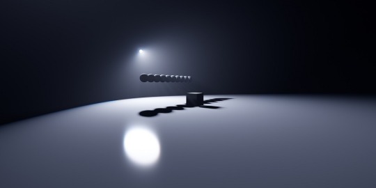
Default spot light.
The same spot light with shadow (very high).
3.3 Fog
When fog is loaded, light streaks are created at the location of the light emitted by the light. There are also special parameters called MiePhase and MieDensity, but be aware that other parameters aren’t isolated. The godray may or may not be displayed depending on the angle and position of the camera. So be careful.
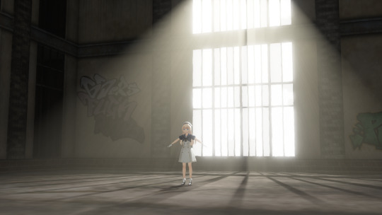
Godray representation using volumetric fog and disk light.
3.4 IES
Reference: unrealengine.com
Simply put, it’s a light which displays the distortion caused by the reflective surface of the lighting fixture, the shape of the bulb, and the lens effect.
It can express a light closer to the one you have at home than a straight spot light like the ones used on stage. You can think of it as basically spot light with just a little distortion in the shape of the light. A point light IES is also spot light.
3.5 LED
Reference: twitter.com
The light source itself is the same as rectangle light, but it can display AVI images or screen images.
In order to display images on the LED light source, load DummyScreen.x in the Extension folder and set the Background (B) in the upper left corner of MMD to ON mode. You can also load the background AVI and change the mode to display any image.
If you just want to display the image, you can set the material of your favorite model to material_screen, but you can use the LED as a light source for the image.
Translator’s note: in practice, it looks like this. In a more straight forward way to explain this, load the LED light and add main.fx to it. Then, load the dummy and select any AVI file or just enable the capture mode. The LED will start capturing the screen and emit light. You can play with the RBG sliders and all. I added a volumetric cube for the dark room effect and Sugiura-san for you to see how the panel behaves. Whenever there’s a change in the captured screen, the light behaves accordingly i.e. a red screen emits red light; a mostly white screen with green details emits white-ish.
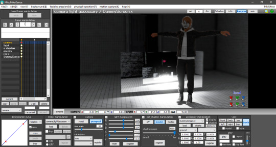
3.6 IBL
This and the GIF sections were writen by the translator, ryuu, as the original author requested information about it.
IBL stands for Image Based Lighting, which is what Raycast does! The image is projected into a sphere and it samples the data to light the objects. All of the skyboxes we use have images in the .dds format for easier rendering.
According to the spreadsheet, the only light capable of using IBL is sphere. To activate it, head to the Default IBL folder instead of the default one that opens when loading light properties. You’ll notice the sphere reacts with weaker lighting, you have to increase the intensity.
The following images are color tests with sphere IBL. The most visible differences are in how RG and RBG react: they produce shades of red and yellow, then white and pink respectively.
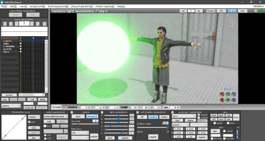
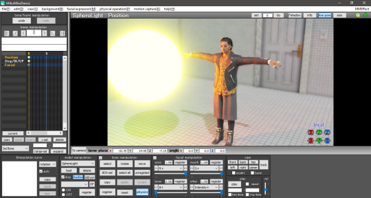

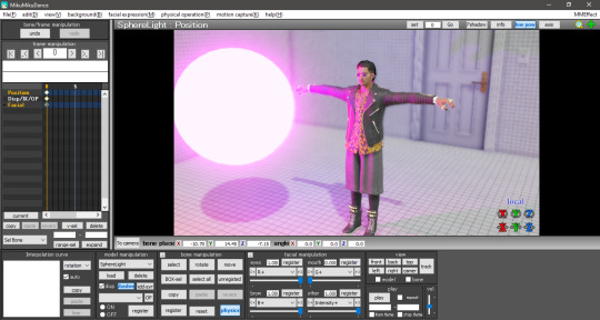

Now with disabled IBL, this making the sphere another common light. The default is very strong compared to IBL, Zhao-san hand’s shadow is even huge on the door behind him.
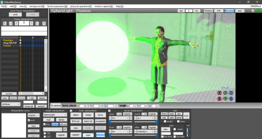

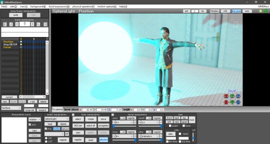
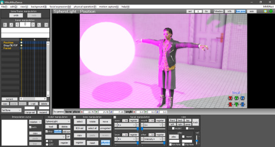
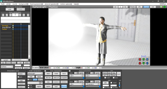
The .dds used was the default one in the Default IBL folder. I haven’t experimented with a different one yet, plus I believe it isn’t any .dds image that’ll work there. If we follow the logic of how custom skydomes are created, a HDR image is needed and you have to “craft” them.
3.7 GIF
A rectangle light can load .gif images and project them on their light, Just load the .fx inside the Default GIF folder to activate it. The default GIF is the following. However, when loaded as light, it doesn’t animate and has some distortions on the edges.

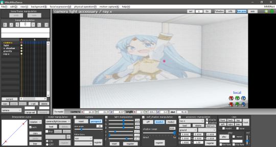
For now, the only advantage I see in using a GIF light is to mimic a projector effect at the cinema. You can use custom images by renaming the default one to rance1 and the new one to rance.
The projection’s size depends on the rectangle’s, so a small rectangle will show a small GIF. Also, keep in mind that the projection is a mirror of the original image.
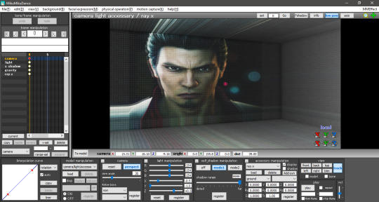
4. FOG
The fog can be used to create realistic perspective, smoke, and air, and it can also be used in conjunction with fog lights to change the atmosphere. It’s important to note that when the fog is loaded, it’s rarely displayed in Model Edit mode, so be sure to check it in Camera mode. In this case, you may need to tweak the model display order a little to get it to show up.
There are four types of fogs: atmospheric fog, ground fog, volumetric cube and volumetric sphere.
4.1 Atmospheric Fog
If you don't know what you're doing, but want to use a fog, just load this to get a sense of perspective (or rather, fading in the distance). So if you have a stage that extends far into the distance, you can use this to get a certain atmosphere.
Also, only the atmospheric fog has multiple fog maps, which can be found in the AtmosphericFog folder with a godray .fx file. You can apply godray to the lighting (sunlight) in MMD and, by assigning a fog map with ...without sky... .fx, you can disable the fog effect on the skybox.
You can also disable the fog effect for skyboxes by assigning a fog map with ...without sky.... .fx.
The number of parameters is overwhelming and difficult to adjust, but it may be easier if you think that the parameters with Mie are related to the lighting (sunlight) in MMD.

Without fog.

With atmospheric fog and changed density and range values. The farther away the image is, the lower the saturation and lightness become. The perspective is clearer. It’s rare to see much difference, but the atmosphere changes quite a bit with and without the atmospheric fog.
4.2 Ground Fog
When loaded, the fog is displayed based on the ground, and its color and height can be adjusted using morphs. The number of adjustable parameters is small, but if you adjust them, you can use it in the same way as the ground-based atmospheric fog.
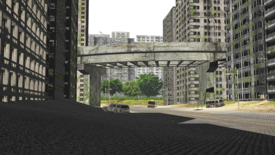
Without ground fog.
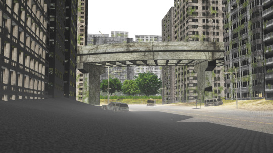
With ground fog.
4.3 Volumetric Cube And Sphere
Unlike the other fogs, these two are only loaded and not applied to the entire room. At first, they only appear small at the foot of the screen and need to be resized to fit the room. By the way, they are basically the same, just round or square. The advantage is that it can be assigned to a limited space only.
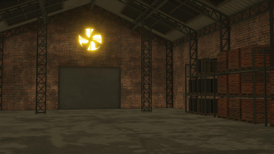
Without light.
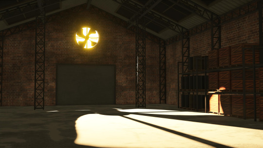
With light.

With light and volumetric fog. It might be good for a dusty atmosphere in a closed room.
5. OTHER TIPS
If you feel that your PC can't handle it, you can lower the shadow to low and get by.
The skybox time of day can be used as a second atmospheric fog which is easy to handle since it is built into the skybox. If you turn off EnvLightMap, Main and MaterialMap, it won't interfere with other skyboxes. It's pretty easy to use, but not for everyone.
Turn on Bokeh (DOF effect of Ray-MMD) and pull the MeasureMode morph of ray-controller to the right to bring the ray.x accessory into focus.
It's a good idea to set the SSAOMap of eyes and face to 0.
6. FINAL NOTES
Stages shown in this tutorial: P.T by G_Wuuuuu, warehouse by hiro K, skyscrapper by 化身バレッタ and abandoned city by NOB.
Models by SEGA.
I tried to keep the translation as faithful as possible to the original documentation. Thank you, ngreeed, for allowing me to share your tutorial with non-Japanese speakers.
Also, I absorbed many knowledge from this tutorial and rendered a new image using the improved technique. Only the sphere light had fog. The colors were applied after adjusting all the lights in their black and white counterpart. Retouched in GIMP.

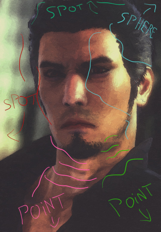

38 notes
·
View notes
Text
Advanced MMD rendering tutorial (and why you should care)
Welcome to another tutorial by yours truly! And this one will be big, so grab your water bottle and focus on my words as I lead you through areas outside of MMD (Ayreon reference, sorry!).
DISCLAIMER: everything is from my experience. I’m not an expert, so don’t quote me on anything here. Thanks.
You may be wondering why the hell did I write you should care about advanced rendering in MMD; after all, we’re in 2021, MMD is obsolete and nobody cares anymore, right? Wrong.
Imagine the following scenario: you have an average low-end pc (old i3, 8gb ram, intel graphics) and barely can render in Blender without almost frying an egg over your cpu. MMD is the best pick for you, as it’s pretty light when not loading Raycast and can do very cool things for less resources (win-win!). Or you simply don’t feel like investing too much in 3D art (my case) and MMD already does everything you need, you’re a simple person.
One day, you suddenly want to leave the MMDC because you’re tired of it and want to join the general digital art community. Rad, right? But the moment you join it, few people take you seriously... The reason? You’re still rendering for the MMDC.
I’m not saying that your renders are shit; however, here’s the catch: you have to improve your rendering quality in order to have a respectable (good) place in the digital art community. 3D is still seen as only useful for NSFW, SFM memes by many people... And they expect amateur rendering. It’s on us to be the change and earn our little spot there. Understand that an average MMD user like you and me will never be huge like the digital artists we see on Twitter. They only grow this big because they shift to Blender.
To make you feel better, underrated artists are as awesome as the huge ones if your skills speak for themselves.
Now a brief Lírio background: I currently own a portfolio with over 300 finished works and have a small, but loyal following on my social media (especially Twitter). The most rewarding thing? To read someone comment they want to learn 3D art because of my renders and see me as an inspiration to them! Even better when they’re willing to learn MMD nowadays! They only say so because I bring quality to life, I make MMD look as respectable as other 3D rendering softwares. If you look at my portfolio, you would’nt guess it’s by a MMDer at first, only after reading the “about me” section. This is empowering for MMDers.
Ok, enough babbling, let’s get started on the tutorial itself! First of all, let’s talk about the most important detail in renders: the pose.
1. POSING
Your lighting can be flawless, but a bad pose will make everything look amateurish.
Pay attention to: clipping and movement. Please, don’t leave everything in the model clipping like hell, don’t close your eyes and hit render.

Example of bad posing; it feels very mechanical, unnatural, stiff.
How do you counter bad posing? By using references! Using references doesn’t make you a worse artist and it’s completely acceptable to do so! If you’re unsure about your pose, check a reference! There are many profiles on DeviantArt which post stock images of a variety of poses for artists, like AdorkaStock (formely SenshiStock), JookpubStock and Null-Entity. A quick stock search on DeviantArt, or even Google, will get you many results. If you want some 2D pose references, it’s good too! I make use of both and human stocks are better for 3D artists.
Pinterest is a very good option for reference hunting too! But don’t copy anything you see there, it’s a douche move! You can be inspired by the art and photography you see there and reference some things. Pinterest is useful for lighting references (we’ll talk about that in a while).
My general posing tip is to respect the model’s capacities, avoid pushing it to the limits! Also, practice posing from scratch, without using premade pose packs. I learned it the hard way because of the game ports. So do like Madonna and strike the pose!
If you prefer rendering portraits like me, things get a little different. Since the scene lacks a lot of points of interest, it’s important to add emotions to the model, play with light, move the eyes, head and neck... Props like cigarettes, flowers, halos, insects, etc are very welcome too! I’ll expand this later on the camera section.

Example of an emotional portrait. Look at how important the facial expressions are to capture Kiryu’s sadness. You may not notice in the finished render, but the right side of his face, that’s resting on Majima’s shoulder, features an almost shut eye because that body reaction is normal when we rest our eyes too close to surfaces, especially when crying!

When posing using a reference, you don’t have to do it 100% accurate. We aim for a fluid and natural pose and it’s difficult to achieve one just like the reference! Here’s an example:


The poses are very similar and my result looks natural, Yagami feels tired and annoyed. The focus, highlited in red, are the hands and the neck movement. When using a reference, we should pay attention to the model we’re working with and adapt the pose. The result is a referenced (not copied) art. Veteran artists can spot traced and copied art right away. Pay thrice the attention when using someone else’s art as reference, never copy their work.
2. CAMERA
The soul of your render. Some people don’t care about camera settings and just go with whatever looks pretty. Please, don’t be like this! Since we’re 3D artists, we must know at least the basics of photography techniques. That’s vital to both framing your scene and making lights, so don’t ignore it.
The most basic, but not least important one is called rule of thirds. The rule of thirds is a 3x3 grid that’s used to define the focus of the composition, where the viewer’s eyes should be captured right away. Your point of interest should be as close as possible to the intersections (where the lines meet).


In a practical example, the rule of thirds effect is loaded and we start playing with the camera settings, like here:


For a portrait, it wouldn’t be good to leave so much negative space (empty areas), so I resized the screen to 1420 x 2048 and moved the camera around to fit the rule of thirds better. In portraits, it’s recommended to have the eyes close or on the intersections, since they give a lot of impact to the scene (even more if B&W!).

The rule of thirds changed to fit the tighter resolution. If I keep this camera setting and change the resolution back to 1920 x 1080, the intersections will change. If I want to give Yagami more room to shine, I can select 1800 x 2048 and change the camera to fit him better.


You may have noticed the camera perspective is set to 15. That’s another important thing we should consider changing depending on the scene! For portraits, a lower perspective is good, around 10~15. Be careful not to use a very low perspective on portraits, the model will look weird!

No perspective. Yagami looks... Off.

The default perspective when we open MMD: 30. It looks alright, but the camera feels distant, you can even see his shadow!

Yagami is looking distorted with perspective 74.

Perspective 10 looks good! I like to use it when I feature a closer shot of the face. There isn’t much difference between 10 and 15.
A higher perspective is good for framing your scene without taking the camera too far from your models. It’s perfect for dynamism!


Also, it’s good to keep your model at the center of the axis for lighting purposes (Raycast in special).

3. LIGHTING
Lighting and camera go hand in hand. The biggest strength of a 3D artist is to be able to play with the light settings in real time, we have it easier; so use it wisely! When it comes to lighting, MMD offers the option to create custom lights by using either Raycast or Cook Torrance (as far as I know). I’ve used the latter for months until I tried Raycast after changing pc specs... And Raycast is much better for the job.
Before I teach you how to do physical lighting in Raycast, I’ll talk a bit about colored and B&W lighting. For colored lighting, it’s better to work with opposites: warm shadows lead to cool lights and vice-versa. Remember that the shadows shouldn’t be deep black when coloring! It simply doesn’t look very good. I’ll give two examples of colored lights in Raycast:

This one uses an all warm lighting scheme and coloring. It looks good for a sunset scene, but lacks that woah factor, you know?

Another all warm scene, but the shading this time looks softer and the shadows are cooler, you can notice them better.

Please, don’t do lights like this. I discarded this one because it looked awful!
Raycast is very powerful for physical lighting for allowing us to add as many lights as we want and have a lot of colors! Including trying neon lighting, which is challenging on its own even for photographers. A good way of practicing lights is by using references (do you remember them from earlier?) of magazine and model shots. If you like to work with game ports, you can try recreating the game’s lighting in your render (and set realistic expectations, of couse).
For B&W, we only work with 50 shades of grey and contrast is very important! Don’t forget to already put a B&W tonemap to your render BEFORE making the lights. To work with B&W, you first must think in B&W and visualize it! Dessaturating the render later will lead to a different (and maybe unpleasant) result, trust me.
It isn’t advised to do very high contrast works in MMD! Nor trying to do high-key B&W! Low-key is very doable, but pay a lot of attention to the darkest shadows, don’t let them be too deep.
A balanced B&W looks like this:

When playing with B&W portraits, the focus is intensively on the eyes! The eyes should be lit, it’s what drags our attention.

The reference. I dessaturated the original game screenshot on GIMP for more accurate lights.

Toon shaded with high contrast play. B&W is awesome for adding a lot of emotions to scenes. Also, the lack of colors makes everything look elegant, sensual and serious.
In portrait photography, there are many light types, i.e.: split, rembrandt, rim... These are shown here:

A very useful one is the rim light, its main purpose is to separate the subject (model) from the background. When light comes from the back of your model, there must be rim light. In MMD, our general source of rim light is an effect called PostRimLighting! I always use it as a shading support for my main lights.
Tip: a colored rim light with Raycast can be very useful for separaring the subject from the background if the colors are very close to each other!
A very basic light setup for studio is three pointlights: a main one with two supports. If working with Raycast, you can add more lights for color fix and better shading.
3.1 COOK TORRANCE LIGHTING
If for any reason you want to try Cook Torrance before Raycast for custom lighting, I’ll cover its basics here! This shader comes with five pointlights and its major drawback is that you can only load up to four at the same time...

These lights are activated once you set the Ry, Rz and Rx values to 1 for default studio lighting or different values for colors. Change the Si value to make the lights stronger or weaker. The Cook Torrance lights feel sharper than Raycast’s for the lack of customization. However, it doesn’t mean you can’t create some good renders with it!

Since you’re limited to four lights at the same time, you should focus on adding the main and support lights, leaving the last one as rim or whatever you want it to be.
3.2 RAYCAST LIGHTING
Now what you’ve been waiting for! I sold myself to Raycast because it’s simply too powerful to be ignored and I’m still learning how to achieve its full potential! The best thing about Raycast is being able to play with light in different ways, like in the example below:

First of all, Raycast comes with a few interesting lights for us to explore, you can find them inside the “lighting” folder.

You must be wondering what are those IES lights and I’ll tell you: these ones are for lamps, man made lights; you won’t be using them by default. These lights are PMX files, meaning they’re models with sliders for custom colors, intensity, hardness, blinking, etc! Now, I’ll also be sharing what I learned from dendewa’s lighting tutorial for Raycast, please check out his works and useful resources for MMD!
The ones we’ll be using a lot are directional light and pointlight. Directional acts like a support for MMD’s default lighting direction, while the others will shape the shading to how we want it to be. When changing the lighting fx in the MME tab, I select ambient with shadow (very high) most of the time. A fog light can be useful for gradient effects, it’s cool!
I haven’t tried every type of lighting yet though. I noticed disk light is very useful for rim lighting and a rectangle light can be useful on windows! I had little contact with spotlight, but I noticed this one is good for shorter range highlights on the model, can be used for rim lighting too (examples later).
4. RENDERING WITH RAYCAST (B&W)
Now that we’ve seen the theory, let’s put everything to practice! Do you remember Yagami from earlier? He’s back to help you understand how everything looks in practice. Welcome back, Tak!
Since it’s an advanced tutorial, I’m expecting you, the reader, know how to load raycast and set it up (materials, skybox). I use dendewa’s blank ibl skybox to make lights from scratch! When loading it, don’t worry about the error you get, it’s normal. As of cloth materials, I’m using this one. The alpha fix is by dendewa.
For now, I haven’t loaded any custom lights yet, so I only had the default MMD lighting with a B&W tonemap. The default lighting is our sun, our direction; I’ll shape the shading around it.

I know he looked weird... I’ll change it later!
The first light I loaded was the directional one to act as a support to the main one and provide some nice shadows. Since I was working with B&W, I set the RGB to 1. The range was set to maximum and hardness was set to 0.8. In the MME tab, I loaded the default ambient with shadow (very high) fx.

The scene looked brighter and had more shadows.
Then I loaded and set up my fist pointlight, which will act as the main one in the three lights system! Range on max, hardness on 0.8, default ambient with shadow (very high) fx. If the light feels too strong, you can increase the attenuation bulb - in the “other” sliders.


Then, proceed to load the other pointlights and position them as you wish. In this render, I focused on bringing the shadows on Yagami’s face to the left side, but kept the dark to light transition smooth so as not to look exploded on his skin. Every pointlight had ambient with shadow (very high) as fx.


Three pointlights and a spotlight for rim lighting on the hair to separate it from the background (more visible later).

The portrait used as reference for this render.
You can hide the pointlights by unchecking their boxes on the MME tab for both main and material map.

Now messing with Raycast’s controller: increased exposure and contrast, reduced gamma and fixed the weird depth of field.

I added two SSAO effects to support Raycast’s default SSAO. PostRimLighting was added as a shading support. The Si value looks high for now, but you’ll notice it was set up for later.

I added my beloved LIGHT ME UP effect for the low-key feeling followed by o_SelfOverlay for blending.


Did you notice how dark the scene got? Yagami’s hair even disappeared in the darkness! I had to make the spotlight stronger by increasing the attenuation bulb +.

Much better. I kiss.
A very important effect to load when making physical lights is LightBloom! This effect mimics how digital cameras perceive light (the soft glare) and, as consequence, brings our lights to life. It comes with a dirt map variation, but it isn’t that noticeable until you set a very high threshold on the controller.
The LightBloom controller comes with five types of sliders, which are:
BloomThreshold: to “activate” the effect and have bloom areas. Focus on adding bloom to areas of focus and interest rather than on the entire scene!;
BloomRadius: keep the radius low when your surface doesn’t bounce or emit too much light, like the skin;
BloomColorAllHSV: makes the bloom’s color warmer, good for warm lighting;
Bloom 1st-5st HSV: this one modifies the brightness and color of the bloom in each layer. I barely touch this sliders because the default bloom already satifies me;
DirtColorHSV: scales the color of the dirt (if LightBloom with DirtMap.x is loaded).
When loaded and set up, LightBloom looks like this! I added FilmGrain for a better digital camera effect.

Optional step: if you need to fix alphas like I did, add Croquis改. This is mostly for my own aesthetic.

And hit render! The final result:

Why is he so handsome?
4.2 RENDERING COLORS WITH RAYCAST
I admit that colors are still my weakness... Although I’m always learning something new and improving my awful color theory. For the second part of this rendering guide, I used Judgment’s box cover as lighting reference because I was clueless:

So here we go: I only kept Raycast’s controller intact, decreased the temperature and added a blue directional light to serve as my shadow. You can change MMD’s default lighting to a blue-ish color if you want.

The main light was a warm pointlight. Added IkClut to help with the blue-yellow coloring.

I kept changing the background color because I’m like that.
I added the blue highlight to the shadow as a pointlight and changed MMD’s default lighting as a test.

More lights were added, but the scene still doesn’t feel right... The lights look too rough on Yagami’s face and the saturation is high. Now here’s a pro tip for you: with Raycast, you can change MMD’s default lighting color for better PostRimLighting’s highlights.


The three pointlights weren’t enough in this case, so I added a spotlight near his face for a pretty highlight and made Raycast’s shadows blue. The lights were hidden in the MME tab.

And changed the background color. Again.
I added some support effects to make things prettier, you know the drill.

I did this experimental thing of adding the alpha fix and not using the alpha materials on the hair... And it worked nicely! It looked too off with Croquis改 for some reason, that’s why I tried it.

Hit render and there you go! The final result:

Yes, I add lipstick to my men.
5. RESOURCES
5.1 GUIDES I USE
B&W portrait guide
A complete guide to B&W photography
Neon lighting guide
How to make your portraits more creative
5.2 EFFECTS
Cook Torrance
PostRimLighting
Raycast
LightBloom
FilmGrain
LIGHT ME UP and CACTUS (BREAK THE COLOR)
o_SelfOverlay
o_Tonemap
Croquis改
6. RENDER CREDITS
Yagami by SEGA and converted to XPS by Xelandis, to PMX by KS.
Cigarette by SEGA, files by Xelandis and converted to XPS by Hatredboy, to PMX by KS.
25 notes
·
View notes
Text
Fixing realistic hair in MMD: the cool guy way
Welcome to an effect tutorial! Here I will cover the basics of mipmapping and teach you how to “fix” realistic hair using MME.
Game ports have been around the MMDC since forever, but MMD struggles to read alpha channels right and the hair looks horrible. Thankfully, I have an alternative solution to that!
Before we start, we need to understand what are mipmaps and how they play a role on realistic hair for MMD.
For starters, the MIP maps, or mipmapping, is a 3D rendering technique that creates many copies of the same texture in different resolution scales, so the image is always clean when you either zoom in or out, distant or not. Check the examples below:


Ok, and how is it related to MMD and realistic hair?
Well, have you ever noticed that MMD’s view tab has an option called “mipmap (anisotropic)”? Nobody talks about it at all, so it is understandable if you haven’t.

As you know, MMD struggles a lot to read realistic hair alphas properly and you must fix it most of the time. However, some models have hair so realistic that you may only think “ok, so what am I supposed to do here? Even with bad alphas, it looks great in PMXe!”

How great king Noctis looks! His hair and beard look fine, oh boy what a great day! Then you open MMD and see this:

Do not worry about him, he is going though adult life crisis.
Wondering what the hell happened there? I tell you: mipmaps. The thing is that PMXe does not have mipmaps (do not quote me on that) while MMD has them, so the texture looks like a mess once you load the model.
If you go to the view tab and disable the mipmapping, you will see that the model is looking good again! However, our job is not done here.

Did you notice the default alpha issues? These white outlines must go away or they will mess with our render! If you turn the default background black, they look much better, go almost unnoticed.

Since MMD’s default background changes from white to black and vice versa depending on the effects you load, I recommend using a solid black skydome behind the model in the draw order with another skydome or stage in front of it, so you keep this “fix”.
Now you decide to continue the project and apply the effects! When it is shading time, the mipmaps simply are on again.

Back to stage 0, I guess...
What happened is that some shaders have mipmaping enabled by default and disabling it on the view tab is no use. Now here is the catch: I did my homework and compiled a list of shaders that do not make up of mipmaps, so you can apply them only to realistic hair.
They are mostly old shaders that people do not bother to use anymore (Ray tutorial coming soon), but if you prefer working with them, here is the list:
Adult Shader;
Dark Adult Shader;
Full Simple Soft SHadow;
Mask Shader;
OverRay Shader;
PmotSkin;
Toon Master.
My favorite one is OverRay because of the highlights, they look great on realistic hair!
For best results, I recommend using o_disalphablend to ease even more the problematic hair alphas and add Object Luminous for the highlights! Example of usage of Adult Shader + Cook Torrance below:


With Adult Shader, Yagami’s hair was “fixed” with the addition of o_disalphablend. The black lines are actually good for separating the hair strands from the background and make good aeshtetics too!
Now a test without Adult Shader on the hair:

Exactly, Yagami-san...
DISCLAIMER: I am not saying you do not need to manually fix the crazy alphas in PMXe because you have this gimmick to back you up. It is a “fix” and may not work in every situation!
11 notes
·
View notes
Text
MMD Cook Torrance shading tutorial + Dry Brush technique
Welcome to this tutorial on how to render images in MMD using my technique!
For this tutorial, we will use an extensive list of effects, but it is subject to change, as it was made especially for my black and white style with low-key lighting. Below is the list of MME used in this tutorial:
Cook Torrance (shader);
o_DisAlphaBlend (optional);
o_DLAA;
Object Luminous (optional);
o_Monochrome;
PointLight (Cook Torrance);
ScreenTex改変-パラ_フレア;
PostRimLighting;
LightBloom;
AbSSAO;
HgSAO;
HgSSAO;
SvSSAO;
SoftLightA (NCHL2 shader);
SoftLightB (NCHL2 shader);
Croquis改;
LIGHT ME UP (BREAK THE COLOR);
o_SelfOverlay;
Draw style;
ikDrybrush.
Each listed effect redirects you to your download page. This tutorial refers to the following image:
Results will vary according to the type of model used; this is a high poly model, so shading is better and much more detailed. I recommend adapting this tutorial to your project.
1. COOK TORRANCE
Before we start, I will give a brief explanation about the functionality of the shader, the main one of this tutorial: Cook Torrance is a powerful shader that allows us to create personalized lighting through points of light; it has variations for more shine (specular and テカテカ), skin (sakura R1 and blight for more shine), toon and normal map.
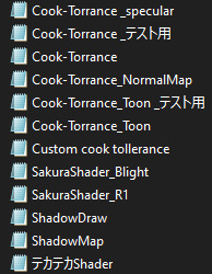
The application of this shader removes outlines and SPA / SPH, so be careful with parts that depend entirely on SPH, such as metals. In the example below, specular variations were applied to the glove and eye patch, テカテ カ to the hair to enhance the highlights and R1 sakura on the skin; the other parts are with the base shader:
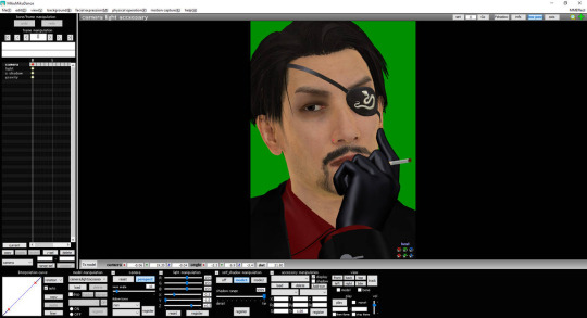
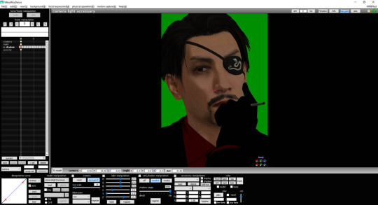
Before and after adding the shader. Note the absence of glare in the glove and the greater definition of the model's shapes.
Inside the shader folder, we can find 5 point light files and another one called ShadowMap.x; I still don't know for sure what the latter does and I get an error message when loading, but, in my view, it makes no difference with or without. As for the point lights, the shader limits the use of 4 points simultaneously, the 5th will not work.
To activate the point light, it is necessary to change its Rx, Ry and Rz values, which work as RGB to give color to the lighting — 1, 1, 1 is the studio white color, standard and the one I use for all my images, since I work with black and white. It is preferable to change the light intensity by changing the Tr value instead of RGB. Move the point lights using the dummy bone (standard MMD model).
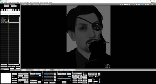
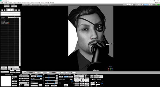
In this case, our 1st point light, the main lighting will be stronger and will repeat the "movement" of the standard MMD lighting you set. In my case, I chose RGB = 100, 100, 100; X = +0.5; Y = - 0.5 and Z = +1.0. Uncheck the display box on the accessory handling panel to hide the point light's model.
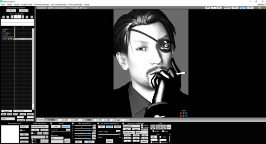
If the Si of the point light increases, the light will be stronger and it will be necessary to reposition it. In certain scenarios, it is preferable to use large point lights that cover more parts of the project. Examples below:
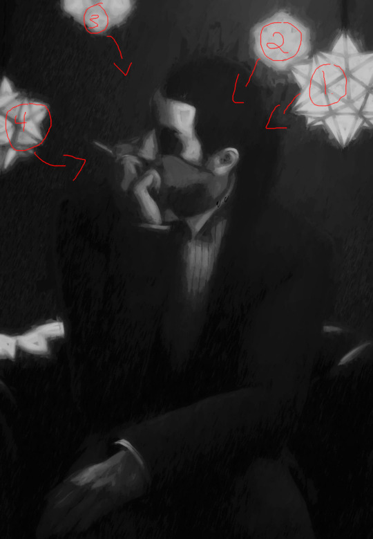
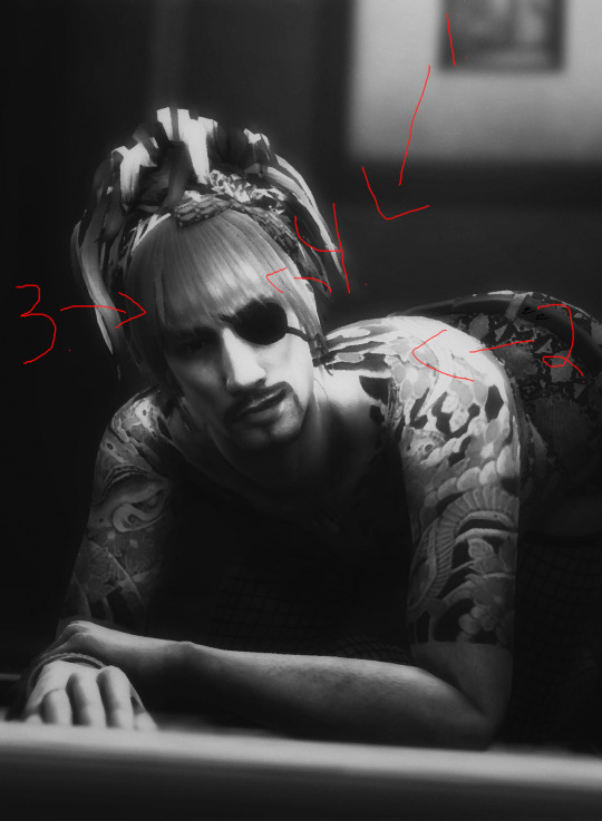
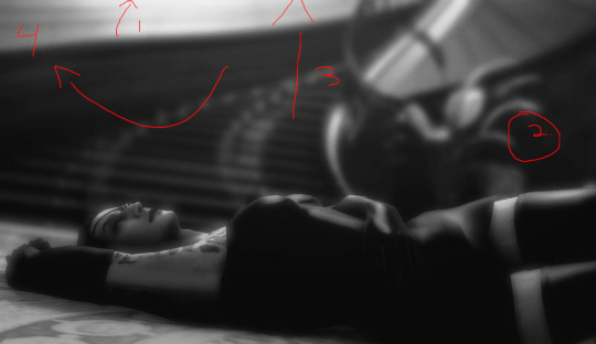
Application of the 2nd point light, which is weaker because it is "auxiliary" light; it will give the glove and hair more shine, in addition to softening the shadows on the left side of the face for a smoother transition:
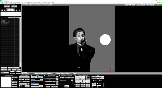
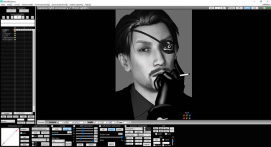

For our 3rd point light, it will have the characteristic of the so-called rim light: this is a photography technique mainly used to separate the object from the background with a lamp behind the subject. In this case, we will use the point light just above the model to add details to the hair strands:
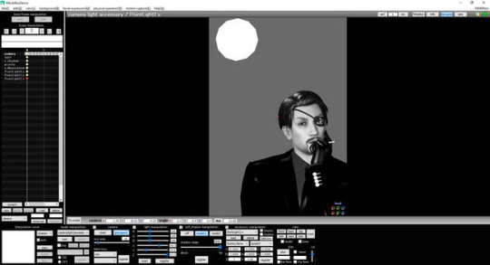
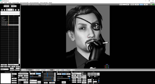
2. OBJECT LUMINOUS
Object Luminous is a versatile and easy-to-apply effect, the effect of which, as the name suggests, gives luminosity to the selected part. In this render, I loaded 2 Object Luminous and put one on the hair and beard, the other on the glove and jacket because they are dark parts that easily disappear when more effects are added.

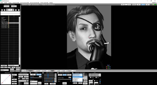
In the hair, the luminosity serves as an aid to the Cook Torrance (variation テ カ テ カ) and gives shape to the hair when configured in low intensity: Si = 0.1, Tr ≤ 0.4 - subject to change according to your needs. Application examples below:
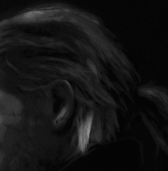
Preferably, move Object Luminous before any effect of changing the color of the screen, such as o_Tonemap and ikClut, otherwise the lighting will be highlighted, producing the very desirable black and white color effect: the so-called color splash.
3. POSTRIMLIGHTING
One of the essential effects for the proper functioning and credibility of Cook Torrance, PostRimLighting creates the rim light, mentioned earlier in this tutorial, in the entire model and highlights its forms; it is important to set Si to at least ≥ 0.3 to support the light created by the light points — a value subject to change as more effects are added.

As Majima's clothes are mostly quite dark, the initial 0.3 needed to be changed to 0.8 at the end of the render, as the image was getting darker.
For lights coming from behind the subject, start with a higher Si value. Example below:

4. LIGHTBLOOM
The role of this set is to soften the lighting and enhance its brightness, mainly because it is a type of "physical" lighting: objects with light properties.
The creator of Cook Torrance recommends combining the shader with Diffusion, but I preferred the results with LightBloom. Inside the effect folder, there is a controller called LightBloomController.pmx and the effect's own files: LightBloom.x and LightBloom with DirtMap.x.
The DirtMap variation serves for natural light and recreates imperfections in the camera lens; as my goal is to create studio lighting, I use the original effect.
When loading the controller, there will be 5 manipulation sliders, these are, according to the author's description:
BloomThreshold: "seeks pixels higher than this brightness level";
BloomRadius: "controls the size of blurring effects as a percentage of the screen width";
BloomColorAllHSV: "scales the brightness and color of the entire bloom effect (linear color space with HSV color)";
Bloom 1st-5stHSV: "modify the brightness and color of bloom in each layer, if you need more bloom, use a higher layer";
DirtColorHSV: "scales the brightness and color of the entire DirtMap".
In short, the 1st step is to set BloomThreshold to 0.5 and adjust the intensity according to your need: the higher the number, the more parts will receive brightness. For low light, it is recommended to use it around 0.6, keep BloomRadius < 0.3 and decrease the intensity in BloomColorAllHSV, leaving ≥ 0.5.

Place PostRimLighting and Object Luminous before LightBloom to soften their lights too.
Then, the shadow effects are added. I use 4 by default: AbSSAO, HgSAO, HgSSAO and SvSSAO — when in need of more shadows, I add o_SSAO with low Si. Each has a purpose in the overall composition, making it important to control the values of Si and Tr according to the purpose of your lighting. I will not discuss how to configure each shadow in this tutorial. O_DLAA is an alternative to common anti-aliasing and reduces, to some extent, the knurling that post effects produce. O_disAlphaBlend serves to fix the alpha channels (transparency). It is important to put both at the top of the list of effects.

The SoftLight A and B effects are part of the NCHL2 shader and act as a more manipulable version of o_BleachBypass, very useful to add contrast to the project. A lightens or darkens the image, while B works as an aid to control gray shades.

It is important to maintain a smooth transition from shadows to less rough brush strokes of dry brush, mainly on the face, due to excessive contrast, as in the following example:
The application of the BREAK THE COLOR effect is done exclusively by the characteristic of "false lighting", extremely useful in low-light or spot scenarios. It is recommended to use Tr ≤ 0.5; increase the Si to give much more contrast, but I don’t think it is necessary, since we have SoftLight and soon o_SelfOverlay. However, feel free to experiment with higher Si. LIGHT ME UP is my favorite variation, for both light and dark scenes, CHATEAU is a great alternative to lighten them up.
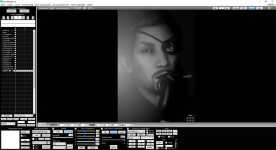
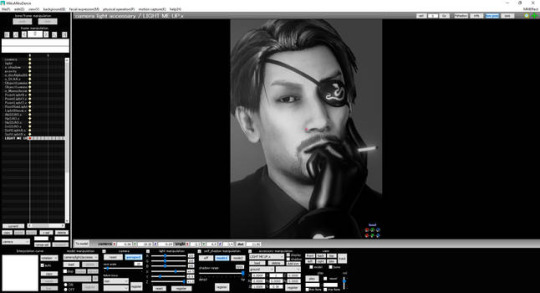
Application of o_SelfOverlay in order to soften LIGHT ME UP and increase the Si of PostRimLighting to delimit body and clothing contours:
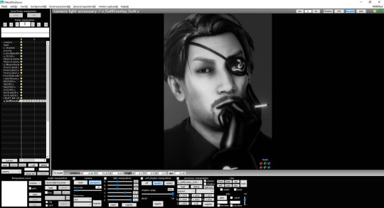
Application of ScreenTex変 - パラ_フレア (variation 墨) for lighting correction. Important to place before PostRimLighting to preserve the edges:
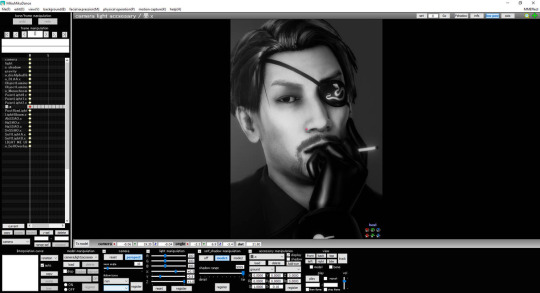
5. CROQUIS
Now the render starts to take the 2D direction when applying Croquis改 and highlight the textures of the model and make smooth outlines; the value that interests us in this case is the Y, which affects the textures.
The goal is to delimit the Drybrush's area of operation and avoid a very blurred and confused image, especially for portraits. In addition, the contours give a greater drawing aspect when rendering.
After many tests, I came to the conclusion that Y ≥ 1 values in low perspective are sufficient for desirable results in the final render: the further you move the camera away, the stronger the lines become, needing to decrease the Tr. It is not recommended to rely on the render preview in MMD, as Croquis tends to weaken.
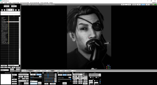
It is good to place Croquis before any post effects for best results.
6. DRAW STYLE
This effect applies a layer that imitates a canvas and has 18 variations, being 9.x more used by me to smooth out the Drybrush's strokes. Recommended to use Tr ≤ 0.4.

7. IKDRYBRUSH
Finally, the effect that creates our painting. When loading it, there are 4 variations of detail: cancel (removes the effect of a certain part), chara (default), face and skydome; it is possible to change the type when loading another FX. I don't mess with these settings, but feel free to experiment with the different types.
To control the brush size, the value of Si is changed, which ranges from 0.5 to 2. Tr will decrease the visibility of the effect — I personally do not change this value.

Like Croquis, the preview of the render will be different from the final result, making it essential for you to experiment with different values . I try to render 3 different files for 0.5; 1 and 2, because 0.5 usually the final image has white lines and dots with a smaller brush, but it is easily corrected when applying the Si 1 layer on top, as in the example below:
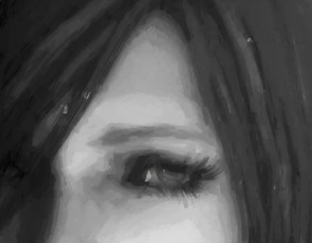
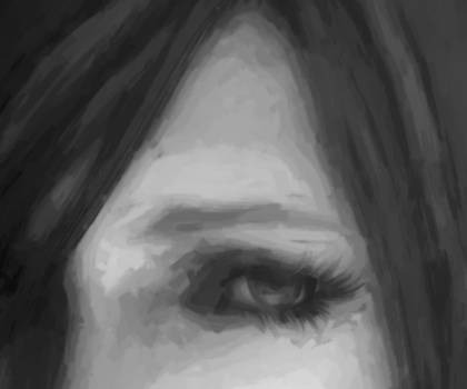
It is up to you how you edit the finished render. I open the extra 2 layers (1 and 2) in GIMP and change their properties to "just darken", so only the dark strokes appear, hiding the white flaws.
7 notes
·
View notes