#Arduino Pro Mini 5V
Explore tagged Tumblr posts
Visit Tumblr Blog
Explore Tumblr blogs with no restrictions, modern design and the best experience.
Last Seen Tumblr Blogs


Fun Fact
Tumblr posted its first advertisements in May 2012 and subsequently earned $13M in revenue.
Text
Arduino Pro Mini 5V

The Arduino Pro Mini 5V is equipped with the 16MHz bootloader. However, ATMEGA328P versions of the Arduino Pro Mini do not include connectors.
The Arduino Pro series is ideal for those who are familiar with the limitations of system voltage (5V), lack of connectors, and off-board USB, as it allows for a quick and efficient setup.
The Pro Mini ATMEGA328P features a micro-controller based on the ATmega328. It offers 14 digital input/output pins (with 6 capable of functioning as PWM outputs), 6 analog inputs, an on-board resonator, a reset button, and holes for attaching pin headers.
The Arduino Pro Mini 5V is designed for semi-permanent use in objects or exhibitions and can be powered and connected to via an FTDI cable using a six pin header. Its pin layout is also compatible with the Mini Arduino.
Features :
ATmega328 running at 16MHz with external resonator (0.5% tolerance)
0.8mm Thin PCB
USB connection off board
Supports auto-reset
5V regulator
Max 150mA output
Over-current protected
Weighs less than 2 grams!
DC input 5V up to 12V
Onboard Power and Status LEDs
Analog Pins: 8
Digital I/Os: 14
0.7×1.3″ (18x33mm)
1 note
·
View note
Text
Arduino Pro Mini 328 5V/16Mhz - Compact Powerhouse for Your Projects!
Unleash your creativity with the Arduino Pro Mini 328, a small yet powerful microcontroller board designed for DIY enthusiasts and professionals alike! With its 5V operating voltage and 16MHz clock speed, this board offers the performance you need for a wide range of applications, from robotics to home automation.
Key Features:
Microcontroller: ATmega328P - the same chip as the popular Arduino Uno.
Operating Voltage: 5V - ideal for compatibility with most sensors and modules.
Clock Speed: 16MHz - ensures fast and reliable operation.
Compact Size: Perfect for space-constrained projects where every millimeter counts.
Low Power Consumption: Efficient design for battery-operated projects.
Whether you're building a smart gadget, a sensor network, or an interactive art piece, the Arduino Pro Mini 328 is your go-to board for reliable performance in a tiny footprint. Ready to take your projects to the next level? Get yours today and start innovating!
Click here to purchase the product: https://dhakarobotics.com/.../1007-arduino-pro-mini-328.../
Contact Us: +8801740298319
visit our website: https://dhakarobotics.com/
##########

0 notes
Text
Test: Flight controller using Pro mini 328/5v 16Hz with 1000kv motors + ESC 30A
FC = ESP32 vs STM32 vs Arduino Board flightcontroller #test #ardujimmy #diydrone
youtube
#flightcontroller#diydrone#arduinoquadcopter#multiwii#stm32#esp32#arduino#arduinoprojects#ardujimmy#Youtube
1 note
·
View note
Text
Buy WAVGAT Pro Mini ATMEGA328P 328 Mini ATMEGA328 5V 16MHz for arduino Nano Microcontrol Micro Control Board
Buy WAVGAT Pro Mini ATMEGA328P 328 Mini ATMEGA328 5V 16MHz for arduino Nano Microcontrol Micro Control Board
WAVGAT Pro Mini ATMEGA328P 328 Mini ATMEGA328 5V 16MHz for arduino Nano Microcontrol Micro Control Board
Check Price

More Description
More photo
View On WordPress
0 notes
Video
instagram
Here is a 4 axis robot arm with smaller gripper and teach mode by Pinaut YouTube Arduino mini pro 5V (Uno, Nano .. what ever...) 4 * micro servos 180degrees 4 * 22k potentiometer (10K is okey!) NmH Battery 4.8V (The Arduino cannot power the servos) Wires, Button, Switch Balsa wood, Metal, Plastic Zip Ties and Glue Teach mode: After a reset the robot arm follows the teach in arm while simple mapping the analog inputs every 25ms to the servo motors. Pressing the button stores each servo position in a array. - - Play mode: The sketch reads the array step by step and and moves the robot arm. For cool loocking movements i added a routine calculates different micro steps for each servo to have moving start and end sync on all axis. Also added a ramp for soft increase/decrease velocity. Shorter travel distances the robot does slow, longer distances with faster speed. - - Play Mode version 1.1 The gripper input is used to set the delay (0,1,3,15,60,300 seconds) after a loop is done. The switch (it was left from the project start) pauses the robot. #arduino #robotics #robotarm #electronics #diyelectronics #stem #stemeducation #servomotor #arduinonano #robotic #diyprojects #arduinoprojects #coding #arduinopromini (at Busan, South Korea) https://www.instagram.com/p/B2dI6oGHDTo/?igshid=n70glslxld1y
#arduino#robotics#robotarm#electronics#diyelectronics#stem#stemeducation#servomotor#arduinonano#robotic#diyprojects#arduinoprojects#coding#arduinopromini
2 notes
·
View notes
Text
Exploring the World of Arduino: Unveiling the Best Compatible Boards for Your Next Project!
Arduino is a popular open-source platform for building electronic projects. It provides a range of microcontroller boards that are compatible with its Integrated Development Environment (IDE). These boards have different features, capabilities, and sizes, which makes them suitable for various applications.
In this blog, we will explore some of the different types of Arduino compatible boards available in the market, including the Decimilia Duemilanove Board, Mega 2560+WiFi R3 Board, and 5V 16MHz Pro Mini ATMEGA328P.
Decimilia Duemilanove Board:

The Decimilia Duemilanove Board is one of the most popular Arduino boards. It is based on the Atmega328P microcontroller and has 14 digital input/output pins, six analog inputs, and a 16 MHz crystal oscillator. It also features a USB port for programming and serial communication. This board is compatible with most Arduino shields and can be programmed using the Arduino IDE.
Mega 2560+WiFi R3 Board:

The Mega 2560+WiFi R3 Board is an upgraded version of the Arduino Mega board. It has 54 digital input/output pins, 16 analog inputs, and four serial ports. It also features an onboard WiFi module, which allows it to connect to the internet wirelessly. This board is ideal for building projects that require high processing power and internet connectivity.
5V 16MHz Pro Mini ATMEGA328P:

The 5V 16MHz Pro Mini ATMEGA328P is a small and compact Arduino board that is ideal for projects with space constraints. It is based on the Atmega328P microcontroller and has 14 digital input/output pins, six analog inputs, and a 16 MHz crystal oscillator. It also features a reset button and a 5V regulator. This board can be programmed using a USB-to-serial adapter and the Arduino IDE.
Apart from these, there are many other Arduino compatible boards available in the market, each with its unique features and capabilities. Some of the popular ones include the Nano, Uno, Leonardo, Due, and Zero boards. Each board has its strengths and weaknesses, and choosing the right one depends on the specific requirements of your project.
Conclusion
Arduino boards come in various shapes and sizes, each with its unique features and capabilities. Choosing the right board for your project can be a daunting task, but understanding the strengths and weaknesses of each board can help you make an informed decision. The Decimilia Duemilanove Board, Mega 2560+WiFi R3 Board, and 5V 16MHz Pro Mini ATMEGA328P are just a few examples of the many Arduino compatible boards available in the market today.
0 notes
Text
pro mini atmega328p
https://sensorembedded.com/index.php?route=product/product&product_id=50&search=pro+mini+atmega328p&category_id=0
This is Pro Mini 5V/16MHz is a 3.3V Arduino running the 8MHz bootloader. Pro Mini ATMEGA328P come without connectors. We suggest the first time Arduino users start with the Uno R3. It’s a huge board that will get you up and running quickly.
0 notes
Text
Minim osd v1 1

Minim osd v1 1 full#
*Note: This is not an original Arduino brand product. Please see the file uploaded under the files tab for Developer credits, Links to source code and other information!
+5V 500mA regulator for up to +12V supply input (5-12v range).
Solder jumpers for combining the power sections.
Two independent power sections with an LED indicator on each.
It features two independent power and ground sections to isolate the OSD's analog stage: a +5V section for the ATmega and the OSD's digital stage, powered through the FTDI cable or other +5V source and a regulated +5V section for the OSD's analog stage, powered through the video in/out header and capable of handling up to +12V input. This was my first go at the MinimOSD for APM 2.5. Programming is done through an FTDI-compatible 6-pin cable. APM Minim OSD V1.1 CNC Aluminum Shell Case Protector Case Black. The one thing I didn't realize is that this board is V0.1 and the latest is V1.1.
Minim osd v1 1 full#
Includes a full Minim OSD - you can use the popular MWOSD which in the latest beta. Packed also with a LC,and 5V 12V bec output,power for OSD,camera,LC filter to avoid the noise. This feature packed board has power distribution for your ESC in a reasonable layout. It's main components are an ATmega328P 8 bit microcontroller with an Arduino bootloader, and a MAX7456 monochrome on-screen display. Apm minim osd v1.1 mini osd cnc trasformati caso di shell protector case nero 63,Acquista da rivenditori in Cina e in tutto il mondo. Power Distribution Pro W/ Minim OSD, & Bec Pro w/ LC Filter /+5v/12v BEC. Its tailored for use with ArduPilot Mega and the MAVlink protocol, and designed to be as small as. It reads all the MAVLink data in the APM telemetry stream and overlays it on the video stream if youre using an on-board camera and wireless video transmitter. It's tailored for use with ArduPilot Mega and the MAVlink protocol, and designed to be as small as possible. This is a mini Arduino based on-screen display board. This is a mini Arduino based on-screen display board.
0 notes
Text

Arduino Mega 2560 R3 (Without Cable)
The Arduino Mega 2560 is an open-source microcontroller board based on ATmega2560. Along with this, it also has 54 digital I/O pins, 16 Analog Inputs, 4 UARTs, ICSP Header, 16 MHz Crystal Oscillator, a reset button, USB port, and a DC Power Jack. It is designed for projects which require more I/O lines, more sketch memory, and more RAM. It is best suited for Robotics, 3D printers, RC planes, etc. projects which require many sensors with different communication protocols and actuators to work in tandem. It gets programmed with the help of Arduino IDE and you do not need to attach any other components to program them. Its uses include in DIY projects, IoT based projects, Robotics, Prototyping for Electronic components and systems. The Arduino Microcontroller boards such as Arduino UNO, Arduino Nano, Arduino Leonardo, Arduino Pro Mini have revitalized the Automation Industry with their sheer simplicity and easy to use interface.
SPECIFICATIONS
The ATmega2560 is a Microcontroller
The operating voltage of this microcontroller is 5V
The recommended Input Voltage will range from 7V to 12V
The input voltage will range from 6V to 20V
The digital input/output pins are 54 where 15 of these pins will supply PWM o/p.
Analog Input Pins are 16
DC Current for each input/output pin is 40 mA
Flash Memory like 256 KB where 8 KB of flash memory is used with the help of bootloader
The Static Random Access Memory (SRAM) is 8 KB
The electrically erasable programmable read-only memory (EEPROM) is 4 KB
The clock (CLK) speed is 16 MHz
The USB host chip used in this is MAX3421E
The length of this board is 101.52 mm
The width of this board is 53.3 mm
Buy this Mega 2560: https://quartzcomponents.com/products/arduino-mega-2560-r3-without-cable
0 notes
Photo


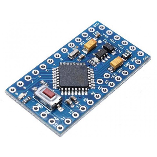
ARDUINO PRO MINI board is one of the application boards. Since it is an application board, it does not have an in-built programmer. USB port and other connectors are also removed. Because once it is placed in an application, programmer and connectors are basically useless.
ARDUINO PRO MINI is of two types; they are differentiated based on CONTROLLER working voltage. One is +3.3V and another is +5V. Choose the appropriate board based on application.
Check out complete technical specifications of Arduino Pro Mini
0 notes
Link
Description: This microcontroller development board has 4 channel 10 bit ADC, 5 PWM pins, 12 DIO, and a hardware serial connection Rx and Tx you are familiar with. Running on 16MHz and 5V, this ...
0 notes
Text
Geekcreit® Pro Micro 5V 16M Mini Leonardo Microcontroller Development Board Geekcreit for Arduino - products that work with official Arduino boards
Geekcreit® Pro Micro 5V 16M Mini Leonardo Microcontroller Development Board Geekcreit for Arduino – products that work with official Arduino boards
Description: This microcontroller development board has 4 channel 10 bit ADC, 5 PWM pins, 12 DIO, and a hardware serial connection Rx and Tx you are familiar with. Running on 16MHz and 5V, this board will remind you a lot of other compatible boards that you like. There is a voltage regulator on board, so it can accept up to 12V DC. If you are supplying an unstable power supply board, be sure to…

View On WordPress
0 notes
Link
0 notes
Text
Inspiration Blog - Entry 1: Micro Servo Robot

The Micro Servo Robot was made using Arduino mini Pro 5V, in which a metal robotic arm mimics the motions of the wooden arm (on the right). So by controlling the wooden arm, we can make the metal arm do whatever we want. The metal arm can even remember the movement we “taught” it and re-perform it.
I think this is a very practical and cool project as the robotic arm can be used to perform tasks that are dangerous. For example, when we solder, the robotic arm can be used because it can withstand the heat while performing tasks with accuracy.
I think the project can be improved by instead of simply mimicing the wooden hand, we can actually control the robotic hand using our own movement (by contracting our muscles, for example).
0 notes
Photo

いまの電子工作ってマイコン制御が中心なのに、アキバってあんまり普通のボードを安く買えないかも。なので当店そこは頑張ります。※税込 Arduino互換機 Digispark 250円 Pro Mini 390円(3.3V版・5V版) Uno 450円 Pro micro 600円 Mega2560 1,200円 --- BluePill 400円 ST-LINK 400円 http://twitter.com/ShigezoneAkiba/status/1167799288925061121
0 notes
Text
Microcontroller SAMD21 (XIAO) von Seeedstudio

In diesem Beitrag möchte ich dir den kleinen Microcontroller SAMD21 von der Firma Seeedstudio vorstellen.

Seeedstudio SAMD21 (XIAO)
Bezug des SAMD21
Den SAMD21 habe ich über aliexpress.com für knapp 5€ inkl. Versandkosten erstanden. Du findest diesen aber auch auf ebay.de für einen Preis von 6€ zzgl. Versandkosten. Lieferumfang Zum Lieferumfang gehört neben dem Microcontroller zwei kleine 7 polige Stiftleisten noch 3 Aufkleber welche die Pinbelegung des SAMD21 aufzeigt.

Lieferumfang des SAMD21
technische Daten des SAMD21
CPU ARM Cortex-M0+-CPU(SAMD21G18) Geschwindigkeit bis zu 48 MHz Speicher Flash 256KB SRAM 32KB Schnittstellen I²C, UART, SPI digitale I/O Pins 11 analoge I/O Pins 11 Stromversorgung / USB Schnittstelle USB Typ C Betriebsspannung 3,3V / 5V DC Abmaße (LxBxH) 20mm x 17mm x 3,5mm
Aufbau
Auf der Vorderseite des Microcontrollers sind neben den beiden SMD LEDs auch die Lötpunkte für den RESET Taster angebracht.

aktive LEDs auf der Vorderseite des SAMD21 Auf der Rückseite findest du die Beschriftung der Pins sowie weitere Lötpunkte für die Stromversorgung und die SPI Kontakte.

Rückseite des XIAO SAMD21 mit Pinbeschriftung Pinout des SAMD21 Zum vergrößern des Bildes, bitte auf das Bild klicken!

Pinout des Microcontroler SAMD21 (XIAO) von Seeedstudio Auf der Rückseite des SAMD21 sind 6 Lötpunkte von welchen 2 mit jeweils "VIN" für die Spannungsversorgung (ohne USB betrieb) und "GND" beschriftet sind, die anderen 4 Lötpunkte sind nicht beschriftet.

Pinout des SAMD21 auf der Rückseite LEDs auf dem SAMD21 Auf dem SAMD21 sind vier SMD LEDs verbaut welche mit den Buchstaben P, R, L & T beschriftet sind. Was die Buchstaben bedeuten kannst du aus der nachfolgenden Grafik entnehmen.

SMD LEDs am SAMD21 XIAO Die interne LED kannst du über den Pin D13 ansteuern (siehe Beispiel "interne LED blinken lassen").
Einrichten auf dem Computer
Der Microcontroller verfügt über eine USB Typ C Schnittstelle und wird mit einem entsprechenden Kabel (nicht im Lieferumfang enthalten) mit dem Computer verbunden. Unter Microsoft Windows 10 wird dieser als "Seeed femto M0" erkannt und eingerichtet.

MS Windows 10 - Gerät "SAMD21" eingerichtet Im Geräte-Manager wird dieser bei mir als "Serielles USB-Gerät" angezeigt.

Windows 10 - Geräte-Manager mit eingerichtetem SAMD21 am COM5 Einrichten von CircuitPython Auf diesem kleinen Zwerg kannst du mit der Skriptsprache Python bzw. MicroPython programmieren. Dafür musst du jedoch zunächst die Firmware einrichten. Das ist recht einfach und in wenigen Schritten erledigt. Gehe zunächst auf die Seite https://circuitpython.org/board/seeeduino_xiao/ und lade dir die ca. 360 KB große Datei "adafruit-circuitpython-seeeduino_xiao-de_DE-6.0.1.uf2" herunter. Wenn du diese Datei heruntergeladen hast, dann musst du deinen SAMD21 mit dem Computer verbinden (soweit noch nicht geschehen) und dir ein kurzes Breadboardkabel mit Steckern besorgen und deinen Windows Explorer öffnen. Auf der Vorderseite sind zwei Lötpunkte mit der Beschriftung "RST" versehen diese musst du nun zwei mal kurz Verbinden / Kurzschließen. Es sollte nun ein zusätzliches Laufwerk "Arduino" angezeigt werden. In dieses Laufwerk kopieren wir nun die heruntergeladene *.uf2 Datei wobei danach das Laufwerk wieder "verschwindet" und kurz darauf der Microcontroller als "Seeedstudio XIAO" erkannt wird und das Laufwerk "CIRCUITPY" angezeigt wird.

Eigenschaften des Laufwerks "CIRCUITPY" unter Windows 10 In dieses Laufwerk können wir nun unsere Python Datei kopieren welche sofort ausgeführt wird. Download und Installation vom Editor Mu Für die Programmierung auf dem SAMD21 kannst du den kostenfreien Editor "Mu" verwenden. Diesen Editor kannst du unter https://codewith.mu/en/download für Windows bzw. Mac herunterladen. Ich verwende einen MS Windows 10 PC mit 64bit und lade mir somit die Version "Windows 64-bit" herunter. Solltest du ein 32bit System verwenden oder nicht genau wissen ob du ein 64 oder 32bit System hast, so empfehle ich dir die 32bit Version welche auf beiden Systemen reibungslos laufen sollte. Nachdem die ca. 65 MB große Datei heruntergeladen wurde muss diese mit einem Doppelklick geöffnet werden. Es startet dann nach einer kurzen Abfrage der Installer. erster Start des Editors Mu Wenn die Installation abgeschlossen ist, dann kann der Editor gestartet werden. Und zunächst wird man aufgefordert einen Modus wählen.

Editor Mu - wählen des Modus In unserem Fall wählen wir aus der Liste den Eintrag "CircuitPython" und bestätigen die Auswahl mit der Schaltfläche "OK". Wenn dein Microcontroller bereits mit dem Computer verbunden ist dann kannst du quasi sofort loslegen, ansonsten erscheint ein Dialog welcher darauf hinweist das kein Gerät verbunden ist.

Editor Mu - kein Gerät gefunden "Hello World!" mit dem Editor Mu auf dem SAMD21 Wollen wir nun unser erstes kleines Stück Code mit dem Editor Mu schreiben und auf den SAMD21 ausführen. Zunächst wollen wir den einfachen kleinen Text "Hello World!" auf der seriellen Schnittstelle ausgeben. Dazu schreiben wir print("Hello World!") und speichern die Datei als "code.py" auf dem Laufwerk "CIRCUITPY" ab. Der Editor Mu liefert zwar die Schaltfläche "Serial" aber leider erscheint dort immer nur eine Fehlermeldung, somit müssen wir uns anderweitig behelfen. Ich nutze hier die kostenfreie Software Putty mit welcher man sich ebenso mit dem Microcontroller verbinden kann.

Putty - Konfiguration für den SAMD21 Wichtig ist das die Baudrate / Speed auf 115200 eingestellt wird und das der COM-Port passt. Ggf. kannst du unter Windows im Geräte-Manager prüfen an welchem COM-Port dein Gerät erkannt wurde. Wenn das korrekt eingestellt ist kann die Verbindung mit der Schaltfläche "OK" aufgebaut werden. Es erscheint dann unsere Ausgabe auf dem Terminalfenster von Putty. Und jedesmal wenn wir am Code etwas ändern und im Editor Mu die Datei speichern wird der Code ausgeführt und das Fenster aktualisiert sich automatisch.
alternative über die Arduino IDE
Wenn dir Putty etwas zu umständlich ist, kannst du auch den seriellen Monitor aus der Arduino IDE nutzen. Zunächst musst du unter dem Menüpunkt "Werkzeuge" den Port des SAMD21 auswählen und startest den seriellen Monitor über die Lupe oben rechts, oder der Tastenkombination "Strg+Umschalt+M".

Editor "MU" mit Ausgabe der Daten im seriellen Monitor der Arduino IDE Der Code erzeugt nun alle 0,5 Sekunden eine Ausgabe auf der seriellen Schnittstelle welche von dem seriellen Monitor der Arduino IDE auf dem Bildschirm ausgegeben wird.
Beispiele mit dem SAMD21
Nachdem wir nun den SAMD21 eingerichtet und das erste kleine "Hallo Welt!" Programm auf diesem ausgeführt haben möchte ich dir nun ein paar kleine Beispiele zeigen welche du mit diesem Programmieren kannst. Ich habe die Pinleisten auf der Rückseite angelötet dieses ist entgegen der bekannten Richtung, das liegt vielmehr daran das der kleine Aufkleber garantiert nicht langlebig ist und somit die Pinbeschriftung auf der Rückseite sichtbar bleibt. Ich habe dir bereits in einigen Beispielen gezeigt wie du mit MicroPython Sensoren & Aktoren auf einem Microcontroller ansteuern bzw. auslesen kannst. Mit CiruitPython funktioniert dieses sehr sehr ähnlich und damit unterscheidet sich die Programmierung nur sehr marginal in zbsp. den verwendeten Bibliotheken. interne LED blinken lassen Im nachfolgenden Beispiel möchte ich nun zeigen wie du die interne LED am digitalen Pin D13 im Intervall von 0,5 Sekunden blinken lassen kannst. import time import board from digitalio import DigitalInOut, Direction # definieren des Pins led = DigitalInOut(board.D13) # definieren das der Pin als AUSGANG dient led.direction = Direction.OUTPUT while True: # aktivieren der LED led.value = True # eine Pause von 0,5 Sekunden time.sleep(0.5) # deaktivieren der LED led.value = False # eine Pause von 0,5 Sekunden time.sleep(0.5) Video LED Wechselblinken Ein großer Vorteil des kleinen SAMD21 ist das dieser auf ein Breadboard gesteckt werden kann (wie auch der Wemos D1 Mini / Pro, Arduino Micro / Nano). Aufbau der Schaltung Für den Aufbau der Schaltung benötigst du: - 2x LED, 5mm, - 2x Widerstand, 220 Ohm, - 5x Breadboardkabel, 10cm, männlich-männlich, - 1x Breadboard 170 Pin, - und natürlich einen Microcontroller SAMD21 :)

Schaltung - Wechselblinken am Microcontroller SAMD21 Quellcode import time import board from digitalio import DigitalInOut, Direction # definieren des Pins led1 = DigitalInOut(board.D5) led2 = DigitalInOut(board.D6) # definieren das der Pin als AUSGANG dient led1.direction = Direction.OUTPUT led2.direction = Direction.OUTPUT while True: # aktivieren der LED1 & deaktivieren der LED2 led1.value = True led2.value = False # eine Pause von 0,5 Sekunden time.sleep(0.5) # aktivieren der LED2 & deaktivieren der LED1 led1.value = False led2.value = True # eine Pause von 0,5 Sekunden time.sleep(0.5) Video auslesen des Temperatursensors TMP36 Als nächstes möchte ich dir zeigen, wie du die Werte eines analogen Temperatursensors TMP36 auslesen und auf der seriellen Schnittstelle ausgeben kannst. der analoge Temperatursensor TMP36 Der analoge Temperatursensor TMP36 verfügt über drei Pins an welche der Minuspol, der Pluspol (3,3V) sowie die Datenleitung angeschlossen wird. Bezug Den analogen Sensor kannst du bei ebay.de für bereits 1,5€ zzgl. Versandkosten erstehen. technische Daten des TMP36 - Betriebsspannung: 2,7V bis 5,5V - Stromaufnahme: maximal 0,5 µA - Toleranz: ±2°C - Messbereich: -40°C bis 125°C Pinout des analogen Temperatursensors TMP36

Pinout des analogen Temperatursensors TMP36 Aufbau der Schaltung Für den Aufbau der Schaltung benötigst du: - 1x analoger Temperatursensor TMP36, - 1x Breadboard, 170 Pin, - 3x Breadboardkabel, 10cm, männlich-männlich, - und natürlich einen Microcontroller SAMD21 :)

Aufbau der Schaltung - Sensor TMP36 am SAMD21

Aufbau der Schaltung - SAMD21 mit Sensor TMP36 Quellcode Den Quellcode habe ich von der Seite "TMP36 with CircuitPython" von Adafruit Learning System und habe diesen "nur" um Erläuterungen zum Quellcode sowie einigen kleineren Formatierungen der Ausgaben ergänzt. import board import analogio import time # Sensor TMP36 am analogen Pin A0 angeschlossen TMP36_PIN = board.A0 tmp36 = analogio.AnalogIn(TMP36_PIN) # Funktion zum berechnen der Temperatur # Zu dieser Berechnung wird die Referenzspannung am # Microcontroller verwendet, da der Sensor Stromabhängig # die Temperatur misst benötigt man die Referenzspannung def tmp36_temperature_C(analogin): millivolts = analogin.value * (analogin.reference_voltage * 1000 / 65535) return (millivolts - 500) / 10 # Endlosschleife counter = 0; while True: counter = counter + 1 # lesen der Temperatur in Grad Celsius temp_C = tmp36_temperature_C(tmp36) # Umwandeln der Temperatur in Grad Fahrenheit temp_F = (temp_C * 9/5) + 32 # Ausgeben der Temperatur print("#", str(counter), "t" , "%03.2f" % temp_C , "°C", "|", "%03.2f" % temp_F, "°F") # eine Pause von 1 Sekunde time.sleep(1.0) Video serieller Plotter der Arduino IDE Die Arduino IDE bietet neben dem seriellen Monitor zusätzlich auch einen seriellen Plotter welcher Zahlenwerte in einem Liniendiagramm anzeigen kann. Dabei muss man als erstes die Legende ausgeben und danach die Werte. Quellcode Damit wir die Daten in dem Liniendiagramm anzeigen lassen können, müssen wir den Quellcode etwas modifizieren. import board import analogio import time # Sensor TMP36 am analogen Pin A0 angeschlossen TMP36_PIN = board.A0 tmp36 = analogio.AnalogIn(TMP36_PIN) # Funktion zum berechnen der Temperatur # Zu dieser Berechnung wird die Referenzspannung am # Microcontroller verwendet, da der Sensor Stromabhängig # die Temperatur misst benötigt man die Referenzspannung def tmp36_temperature_C(analogin): millivolts = analogin.value * (analogin.reference_voltage * 1000 / 65535) return (millivolts - 500) / 10 # Endlosschleife while True: columns = "Celsius Fahrenheit" temp_C = tmp36_temperature_C(tmp36) temp_F = (temp_C * 9/5) + 32 print(columns) print("%03.2f" % temp_C ," ", "%03.2f" % temp_F) time.sleep(1.0) Ausgabe Read the full article
0 notes