#Auxiliary and main high-capacity engines
Explore tagged Tumblr posts
Visit Tumblr Blog
Explore Tumblr blogs with no restrictions, modern design and the best experience.
Last Seen Tumblr Blogs


Fun Fact
In Q3 of 2020, 31% of US users access the Tumblr app daily.
Text
Auxiliary and main high-capacity engines that are mounted on a ship or on land are repaired and maintained by RA Power Solutions Pvt. Ltd. More than 1500 ship auxiliary engine overhauls have been completed by our company. All parts replacements and repairs for diesel engines are done with a warranty. Contact us by phone at +91-9582647131 or +91 9810012383, or send an email to [email protected] if you need repair, maintenance, or overhaul of a diesel engine or Overhaul & Maintenance of a MAN B&W engine.
#Overhaul & Maintenance of a MAN B&W engine#Maintenance of a MAN B&W engine#Auxiliary and main high-capacity engines#ship auxiliary engine overhauls#main high-capacity engines
0 notes
Text
Marine Internal Combustion Engine Market Report: Opportunities & Challenges

Overview of the Marine Internal Combustion Engine Market
The global marine internal combustion engine market continues to expand as maritime trade and naval operations increase worldwide. These engines are fundamental in propelling various types of vessels including container ships, bulk carriers, tankers, and cruise ships. As sustainability regulations evolve and fuel efficiency becomes a critical concern, technological innovation is reshaping the marine ICE landscape.
Request Sample Report PDF (including TOC, Graphs & Tables): https://www.statsandresearch.com/request-sample/18737-global-marine-internal-combustion-engine-market
Marine Internal Combustion Engine Market Segmentation by Engine Speed
Low-Speed Marine Engines
Low-speed engines (typically under 300 RPM) dominate the large vessel segment due to their high fuel efficiency and reliability. These engines are ideal for:
Large container ships
Bulk carriers
Oil and LNG tankers
Key advantages include longer maintenance intervals and the ability to burn low-cost heavy fuel oil. They are often two-stroke engines with direct drive systems connected to the propeller shaft, minimizing mechanical losses.
Get up to 30%-40% Discount: https://www.statsandresearch.com/check-discount/18737-global-marine-internal-combustion-engine-market
Medium-Speed Marine Engines
Medium-speed engines (400–1,200 RPM) serve a broad range of applications from cargo ships to ferries. Their versatility makes them suitable for:
Auxiliary engines on large vessels
Main engines for smaller vessels and ferries
Naval and government vessels
Medium-speed ICEs often use a four-stroke cycle and are adaptable for dual-fuel configurations, allowing compliance with emissions standards such as IMO Tier III.
High-Speed Marine Engines
High-speed engines (above 1,200 RPM) are preferred in lightweight vessels requiring rapid maneuverability and frequent start/stop operations. They are extensively used in:
Patrol boats
Yachts
High-speed ferries
Rescue vessels
These engines are characterized by compact design, high power-to-weight ratios, and compatibility with advanced electronic control systems.
Applications of Marine Internal Combustion Engines
Container Ships
Global trade dynamics make container ships one of the most demanding applications for marine ICEs. Low-speed, large-bore engines are often used for continuous, long-haul voyages. Fuel optimization and emission compliance are primary concerns.
Bulk Carriers
Engines for bulk carriers prioritize load handling efficiency, long-term reliability, and ease of maintenance. Medium- and low-speed engines dominate this sector, often optimized for long voyages and high load capacities.
Tankers
Tankers require engines that provide consistent propulsion power and high safety margins under volatile cargo conditions. Dual-fuel ICEs capable of switching between marine diesel oil (MDO) and liquefied natural gas (LNG) are increasingly preferred.
Cruise Ships
Cruise vessels emphasize low vibration, low emissions, and fuel flexibility. High-efficiency medium-speed four-stroke engines paired with electric propulsion systems are commonly installed to improve onboard comfort and reduce environmental impact.
Marine Internal Combustion Engine Market Regional Insights
Asia-Pacific
Asia-Pacific holds the largest share in marine ICE manufacturing and consumption. Countries such as China, South Korea, and Japan have well-established shipbuilding industries. The region is a hub for innovation in dual-fuel technology and LNG propulsion.
Europe
Europe is leading the transition towards sustainable maritime propulsion. Engine manufacturers in Germany, Norway, and Finland are developing cutting-edge hybrid and low-emission solutions that align with EU environmental regulations.
North America
The North American market is seeing steady demand from inland waterway vessels and coastal shipping. Regulatory enforcement from the EPA and IMO drives demand for engines with advanced emission control technologies.
Middle East and Africa
This region is witnessing growing demand from offshore platforms, crude carriers, and naval vessels. Engine retrofitting and aftermarket services are becoming prominent revenue streams.
Key Manufacturers
Hyundai Heavy Industries: A global leader in two-stroke marine engines, offering a broad range of low- and medium-speed products.
MAN Energy Solutions: Known for large bore two-stroke and medium-speed four-stroke engines with advanced emissions systems.
Caterpillar (MAK): Supplies medium- and high-speed marine ICEs with modular configurations.
Rolls-Royce (MTU): Specializes in compact high-speed engines with digital control systems.
Mitsui Engineering: Renowned for long-life low-speed propulsion engines.
Yanmar and Daihatsu: Offer compact and efficient engines for coastal and workboat segments.
Marine Internal Combustion Engine Market Growth Drivers and Trends
Decarbonization Pressure: Transition to LNG, hydrogen, and ammonia-capable engines is accelerating.
Hybridization: Integration of ICEs with battery-electric propulsion systems is gaining momentum.
Digital Engine Management: Real-time analytics, predictive maintenance, and fuel optimization software are standardizing across fleet operators.
Retrofit Solutions: Aging fleets are being upgraded with compliant engines and scrubber technologies.
Tier III Compliance: Innovations such as exhaust gas recirculation (EGR) and selective catalytic reduction (SCR) systems are now industry standards.
Forecast and Marine Internal Combustion Engine Market Outlook (2025–2032)
The global marine internal combustion engine market is projected to grow steadily, with CAGR estimates between 4.2% and 6.5% during the 2025–2032 period. The push for greener maritime operations, the rise in naval procurement budgets, and recovery in global shipping trade are expected to stimulate sustained demand.
Strategic Recommendations
Invest in Dual-Fuel Technology: Manufacturers should prioritize R&D in engines compatible with LNG and ammonia.
Expand Aftermarket Services: Offering lifecycle engine management and upgrade services can boost long-term revenue.
Localize Production: Establish manufacturing bases near high-demand regions to reduce lead times and costs.
Digital Integration: OEMs should embed smart engine diagnostics and remote monitoring capabilities as standard features.
Purchase Exclusive Report: https://www.statsandresearch.com/enquire-before/18737-global-marine-internal-combustion-engine-market
Conclusion
The marine internal combustion engine market is on a transformative trajectory shaped by stringent emission regulations, advancements in hybrid technologies, and globalization of trade routes. Stakeholders who align product innovation with compliance and operational efficiency will be best positioned to lead in the coming decade.
Our Services:
On-Demand Reports: https://www.statsandresearch.com/on-demand-reports
Subscription Plans: https://www.statsandresearch.com/subscription-plans
Consulting Services: https://www.statsandresearch.com/consulting-services
ESG Solutions: https://www.statsandresearch.com/esg-solutions
Contact Us:
Stats and Research
Email: [email protected]
Phone: +91 8530698844
Website: https://www.statsandresearch.com
0 notes
Text
Pressure Vessel Parts and Their Functions

Pressure vessels are crucial components in a wide range of industries, from petrochemical and pharmaceutical to food processing and power generation. They are engineered to safely hold gases or liquids at a pressure substantially different from the ambient pressure. While the structure as a whole is important, understanding the individual pressure vessel parts is essential for maintenance, safety, and operational efficiency. This guide dives deep into the key components that make up a pressure vessel, shedding light on their functions and importance.
What Is a Pressure Vessel?
A pressure vessel is a container designed to hold substances under pressure. These vessels are built according to strict codes and standards, such as ASME Boiler and Pressure Vessel Code (BPVC), to ensure safety and reliability. They can range from small cylinders to massive storage tanks, depending on their application.
Key Pressure Vessel Parts and Their Functions
To maintain performance and safety, it's critical to understand the core parts that make up a pressure vessel. Below are the most vital components:
1. Shell
The shell is the main body of the pressure vessel. Typically cylindrical, it bears the internal pressure and defines the vessel's overall capacity.
Function: Contains the pressurized fluid or gas.
Material: Usually made from carbon steel, stainless steel, or alloy steel.
2. Heads (End Caps)
The heads are the end closures of the vessel and are either hemispherical, elliptical, or flat in shape.
Function: Seal the ends of the shell and manage internal pressure distribution.
Types:
Hemispherical heads (strongest)
Elliptical heads (most common)
Flat heads (used in low-pressure applications)
3. Nozzles
Nozzles are pipe connections attached to the shell or heads to allow the entry and exit of fluids.
Function: Facilitate process connections, instrumentation, and pressure relief.
Placement: Strategically located based on process design.
4. Supports
Supports hold the vessel in place and vary based on the vessel's orientation and size.
Types:
Skirt supports (vertical vessels)
Saddle supports (horizontal vessels)
Leg supports (small vessels)
Function: Maintain stability and distribute weight evenly.
5. Manways and Handholes
These are openings that allow for internal inspection and maintenance.
Manways: Large enough for personnel entry.
Handholes: Smaller, for tool access.
Function: Enable safe access to the vessel's interior.
Additional Components of Pressure Vessels
In addition to the primary pressure vessel parts, several auxiliary components enhance functionality and safety:
Safety Valves
Purpose: Prevent overpressure conditions by releasing excess pressure.
Location: Typically mounted on the top nozzles.
Gaskets and Seals
Function: Ensure leak-proof connections between flanges and nozzles.
Material: Varies based on the medium being contained (e.g., rubber, PTFE, graphite).
Flanges
Use: Provide detachable connections for cleaning, inspection, and maintenance.
Type: Weld neck, slip-on, blind, and threaded.
Insulation and Cladding
Purpose: Minimize heat loss and protect personnel.
Material: Often fiberglass or calcium silicate covered with aluminum or stainless steel cladding.
Design Considerations for Pressure Vessel Parts
Each part of a pressure vessel must be meticulously designed to handle specific stress and operational conditions.
Material Selection
Choosing the right material is crucial for withstanding pressure, temperature, and corrosion:
Carbon steel for general applications
Stainless steel for corrosion resistance
Hastelloy and Inconel for high-temperature environments
Stress Analysis
Stress analysis ensures that each component can withstand:
Internal and external pressures
Thermal expansion
Vibration and fatigue loads
Corrosion Allowance
A corrosion allowance is often included in the wall thickness to extend the service life of the pressure vessel.
Importance of Regular Inspection and Maintenance
Understanding pressure vessel parts enables better inspection routines and maintenance planning:
Visual Inspections: Identify surface cracks, corrosion, or deformation.
Non-Destructive Testing (NDT): Methods like ultrasonic testing and radiography can detect internal flaws.
Documentation: Maintain logs of inspections and part replacements for compliance and safety.
Conclusion: Why Knowledge of Pressure Vessel Parts Matters
Whether you are a plant manager, engineer, or maintenance technician, a solid understanding of pressure vessel parts is key to operational success. From ensuring safety through reliable components like heads, nozzles, and safety valves, to optimizing efficiency with proper material selection and support design, each part plays a pivotal role.

At Ribo Industries, we specialize in the design, manufacturing, and maintenance of high-quality pressure vessels tailored to meet industry standards and customer requirements. With our deep expertise in pressure vessel parts and assemblies, we are your trusted partner for dependable, high-performance solutions.
Stay ahead of safety protocols and operational efficiency by partnering with experts who understand the pressure vessel from the inside out.
0 notes
Text


William Mulholland the chief engineer of the Los Angeles aqueduct and reservoir system and much of its roads in the pacific palisades area.
As a long term resident of Malibu, I'd like to explain why I think the system ultimately failed catastrophically.
The open reservoir system in Los Angeles, implemented under William Mulholland's leadership, reflects both the prevailing engineering practices of the early 20th century and some of his limitations as a self-taught engineer. While the use of open reservoirs was standard at the time for water storage, the long-term consequences of this system—such as evaporation, contamination risks, and inefficiency—could suggest a lack of foresight or comprehensive understanding of more advanced alternatives.
As a self-taught engineer, Mulholland's approach relied heavily on practical experience and what was already proven to work. This sometimes limited his ability to anticipate or address long-term, systemic issues. His reliance on open reservoirs underscores some of the limitations of his expertise. His decisions were driven by immediate practicality and economic constraints rather than long-term planning or advanced theoretical understanding
The aqueduct system was designed primarily for efficiency in delivering water over long distances using gravity, but it lacked significant backup systems or alternative water sources for emergencies, such as fires. Fires often demand large amounts of accessible water in urban areas, but the aqueduct system did not include sufficient localized storage or auxiliary pipelines to ensure water delivery when the primary system was disrupted.
Formal training in civil or hydraulic engineering might have exposed Mulholland to concepts like system redundancy, emergency planning, and distributed water systems that could mitigate fire-related risks. Advanced knowledge of materials science and structural engineering might have led to more fire-resistant construction materials and methods.
Relying solely on gravity-fed water delivery in the Los Angeles Aqueduct system was a significant factor contributing to inconsistent or insufficient water pressure in fire hydrants, especially in urban firefighting scenarios. While gravity-based systems are cost-efficient and reliable under normal conditions, they come with inherent limitations that were exacerbated by Mulholland's design choices and the lack of complementary infrastructure.
Fire hydrants in areas that were uphill from the aqueduct or localized reservoirs often experienced low or no water pressure because the system lacked pumps or booster stations to maintain adequate flow.
Mulholland's reliance on a single, gravity-fed system prioritized efficiency and cost savings but ignored the diverse demands of urban water usage, including firefighting. Without auxiliary pumping stations or pressurized mains, the system could not adapt to localized needs like firefighting in dense or elevated areas.
The aqueduct provides water to various reservoirs and local tanks, which serve as key sources for firefighting efforts. If these reservoirs were depleted due to the high demand caused by the fires, it reflects a limitation of the system in handling emergency scenarios, despite the aqueduct delivering water to the area.
The aqueduct’s capacity to deliver water under gravity flow to distant areas like Pacific Palisades can be impacted by high demand, especially in areas with hilly terrain. The local distribution infrastructure connected to the aqueduct, including the reservoirs, struggled to meet the urgent need during the fire, leading to low pressure.
1 note
·
View note
Text
MECHANISED ROAD SWEEPING MACHINES – FOR CLEANER & SAFER ROADS
Roots RSB 6000 Truck Mounted Road Sweeper
In this modern day with ever increasing traffic, the biggest challenge is the sharp increase in road accidents. Two and three-wheeler riders accounted for 40% of all traffic fatal accidents in India, according to WHO’s Global Status Report on Road Safety and India ranks first in the number of road accident deaths across the 199 countries and accounts for almost 11% of the accident related deaths in the World.
Civic Bodies face a real challenge of maintaining cleaner and safer roads free from fine sands. Fine sand that gets accumulated near the center median and on the side of the roads is a major threat to two wheeler riders who have to navigate through with extra caution. To sweep these sands, Urban Local Bodies (ULBs) are engaging conservancy workers, who manually sweep the accumulated sand mounds near the center median. However the constant vehicle movement, dissolves the mounds by pushing the sand back on to the road, giving a tough time to motorists who struggle for balance, especially two-wheeler riders.
Also known as City Sweepers, the Truck Mounted Sweepers come as a boon and a great solution in resolving this day to day challenge faced by Municipal Corporations in ensuring cleaner and safer Roads for motorists to commute…
Roots Multiclean Ltd is the Leader in the cleaning Industry with wide range of mechanized cleaning solutions for almost three decades. Our innovative and hi-tech Road sweeping machines also known as City Sweepers are manufactured at the state-of-the-art manufacturing facility in Coimbatore.
With the experience of offering City Sweepers for over 20 years now, Roots Multiclean Ltd is proud to offer the RSB 6000, the High-Performance Road sweeping Machine, a truck mounted sweeper, with maximum performance, strength, efficiency and productivity.
The RSB 6000 City Sweeper comes equipped with unbeatable features and innovative technology.
As the name suggests, The Truck Mounted Sweepers are sweeping units mounted on to a Truck for primary movement and the functions of the sweeping unit is controlled by an Auxiliary engine.
The Powerful yet fuel efficient Auxiliary engine, powers the broom and vacuum functions of RSB 6000. While in operation, the Side & Center Brooms dislocates the sand/debris from the surface and moves it towards the Suction Head, which effectively picks up all the debris and collects in to the Hopper. The RSB 6000 offers a Hopper capacity of 6 cu.m. This large hopper supports uninterrupted and large area coverage.
The Hydraulically operated Hopper Door has an opening angle of 90º with Hydraulic locking system. The controls from inside the cabin, make it a safe system and easy to operate always.
The challenging part of Dust suppression even in heavy sand/dust accumulated surfaces is taken care by Water Suppression at source. Dust suppression by water sprinkling through multiple different nozzles ensures Dust suppression at its best. Flying dust inside the hopper is also totally arrested by continuous water spray making RSB 6000, an all Weather Runner.
The Polypropylene main Broom combined with the Spring Steel Side Brushes ensures excellent sweeping performance every time. The Two free floating Suction hoods on either side with the choice of operating any one hood independently or both simultaneously depending upon the need offers supports excellent sweeping performance.
Safety parameters have always been an important aspect of machines from RMCL’s stable and RSB 6000 is no exception… The Hopper load holding valve in addition to the Manual safety lock to ensure additional safety is a classic example in addition to Auxiliary engine control unit with automatic safety shut down, Hopper home position indicator, Hopper overload indicator, warning beacon etc.
Equipped with an option of High Pressure water jet of 130 bar, this machine makes it simple to clean sign boards, monuments, paver blocks on the walking tracks, barricades and any kind of stubborn and sticky dirt on different surfaces.
Inbuilt water tank of 1000 Liters, this machine offers an optional tank of 800 liters.The In-built wander hose system ensures Gutter and difficult to access area cleaning a simple task.
RSB 6000 Sweeping kit is engineered to suit different brands of international Trucks.
Thanks to the robust and rugged construction, the RSB 6000 Road Sweeper offers excellent sweeping performance even in challenging working conditions in Ports, Container terminals & Manufacturing units and many ULBs across India.
0 notes
Text


SmartGen | ACC5100 Controller Rolled Out
ACC5100 Diesel Air Compressor Controller is used for air compressor with diesel-driven engine to realize start/stop, data measurement, maintenance, alarm protection and “Three Remotes” functions. It can automatically adjust speed based on the discharge pressure of air compressor, and control various ECU or non-ECU diesel air compressors.
Functional Features
• Five active relay outputs connect with the positive and negative directly, no need to extend external relays with 15A capacity
Five digital inputs can be configured as active under high level or low level, which is highly flexible
Six analog sensor inputs, three of them can be configured as general resistance/current/voltage type sensor inputs
Manual DPF regeneration function supports non-road Stage IV engines
Control functions of heater, cooler, fuel pump and screw oil cooler
Real time clock, Event log (200), Maintenance (10) and ECU information display
With CANBUS port, it can collect the data, protect and control the ECU engines
With RS485 communication port, it can realize “Three Remotes” function
Advantage I: Colorful large screen, HD display
3.5-inch color LCD display, 320x240 pixel resolution, with adjustable backlight brightness
Smart LCD heating system allows it to work normally under low temperature of -40°C
Optional languages of Chinese, English and Russian, which supports custom languages
The description bar in the controller main screen can be configured, which contains ten letters/digits, or five Chinese characters
The analog parameter display area in the controller main screen can be configured, which can display different analog parameters
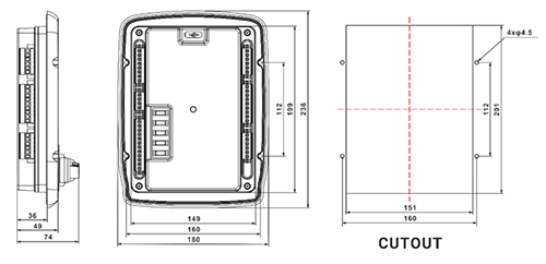
Advantage II: Highly integrated, installation design without fixed on cabinet
· Front panel integrates power on/off switch knob, high/low pressure switch knob, and emergency stop button to save the customer’s cost · The connection wires between ports and components are reduced to be installed flexibly, which improves space efficiency and overall appearance · Equipped with waterproof and dustproof screws installation · With cover for the emergency stop button, it can avoid the touch by mistake
Advantage III: Reliable design for using safely
· It adopts 15A plug-in automotive blade fuses for easy maintenance · Plastic sealing gasket is designed for back enclosure, which has great dustproof performance and allows it to work in extreme environment · General Type-C port with dust cover ensures high IP level · Connection terminals with flange structure makes the harnesses be fixed tightly · Dual wires of B+ and B- meet the requirement of power input
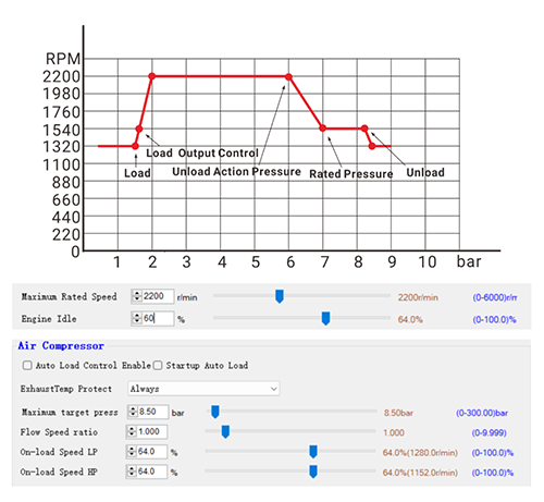
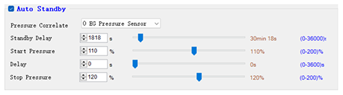
Advantage IV: Smart control of engine speed for variable need
Engine speed can be automatically adjusted based on the discharge pressure of air compressor
Advantage V: Smart control for high automation level
Speed down control when overloaded: ①When the load rate is too high, the speed will be automatically reduced to the stable speed ②When the load rate gets normal, the speed will return to the rated speed ③The speed down rate and delay value can be adjusted
Auto standby control: ①It can realize automatic control of standby and shutdown based on the discharge pressure ②It can be correlated with discharge pressure sensor and other auxiliary sensors
Auto unload control when overpressure: It can realize automatic control of unloading based on the discharge pressure
Overall Dimensions
For more product details, please contact SmartGen business personnel in your region. Welcome your order! SmartGen, Making Control Smarter!
www.smartgen.cn
0 notes
Text
Transfer Tower Bare Machine Manual (Ranking of Inner Mongolia Bare Bend Processing Machine)
Summer is here again. The summer in Dongguan is particularly hot. Many machines work in the case of hot conditions. There will be some problems. The CNC busbar machine will also have some problems due to the hot climate, which will affect the company's normal operation. Therefore, in the summer, it is necessary to maintain and protect the bus and other machinery. So how do we care about it? Let's take a look at the row parent line machine manufacturers! First of all, when we start working, we must carefully check the workbench, line line guide rail and main sliding surfaces, such as obstacles, tools, impurities, etc. It must be cleaned up, wiped, and oil, and carefully check whether the equipment mobile institutions have new pulling, research, and bumps. If there should be a notification of the equipment staff to check the analysis of the analysis, it should be caused by the fault, and make a record to check the safety protection, check the safety protection, check the safety protection, and check the safety protection. The power supply, limit and other devices should be complete. Check that the electrical power distribution box should be closed firmly, the electrical ground is good, and the attachment of the equipment is good.
Multi -site CNC bus processing machine (perforation is normal or turning tower type) is mainly suitable for high and low voltage switching cabinets and transformer manufacturing industries for processing various specifications of copper and aluminum parent lines. As long as the user can carry out the homeline, cutting, and folding processing on the corresponding processing unit, and the production efficiency is high. Transfer Tower Bare Machine Manual
Modern CNC systems mostly integrate PLCs in it, while CNC and PLC communicate with each other in a series of interface signals. Some failures are related to the interface signal error or loss. Some of these interface signals can be displayed on the corresponding interface board and input/output board. The signals can be mixed with the PLC programmer. This inspection method requires maintenance personnel to be familiar with the interface signal of the machine tool and the application of the PLC programmer.
To complete the entanglement of a coil to the Tower Bare Machine instructions, it also requires many auxiliary processes to cooperate. Today, in order to reduce the working strength equipment of the operator, the auxiliary device such as pneumatic execution parts is used to complete the auxiliary process, which shortens the time of the winding operation and improves. The production capacity of the bus machining machine. Specializing in the production and sales of twisters, parent wire machines, automatic winding machines, fully automatic bus, transformers, motor bus, coil parent line machine, heating wire pavement machine, lacquer cable parent wire machine, high -frequency transformer, high -frequency transformer, high -frequency transformer The parent wire machine, the motor bus, the single -axis bus, the multi -axis bus, the solenoid valve bus, the high -speed bus, the CNC winding machine, and various non -standard machinery equipment. Essence
The number of gears: the more gears, the more you can allocate the motivation of the engine, making the acceleration process more stable and stable, which has a great impact on the acceleration time and the middle acceleration.
If the plug of the solenoid valve coil is equipped with a light -emitting diode power indicator, then the pair should be connected when the DC power supply drives the solenoid valve, otherwise the indicator will not light up. In addition, do not replace the power plug in the power supply instructions of different voltage levels with different voltage levels, which will cause short -circuit or light -emitting diode in a low -voltage diode (replacement of low -voltage level plugs with low voltage levels). High -voltage level plug). Transfer Tower Bare Machine Manual
From the perspective of customer experience, the parent line processing machine is a combination of high -tech advanced technology and adopting the concept of high -efficiency energy -saving design to realize the cutting, rushing, folding, processing processing of processing, processing of processing, technology content, production efficiency, etc. It not only meets the urgent needs of the market, but also brings great convenience to users.
0 notes
Text
Ethiopia 8-12T/H Customized Pellet Feed Plant For Chicken and Cattle Feed Production
Name: Animal Pellet Feed Factory
Country: Ethiopia
Date: 2022.11.20
Capacity: 8-12ton per hour
Feed Type: chicken feed and cattle feed
Factory size: 70*50m
Customer's Main Raw material: Corn, wheat, Soybean Meal, and other Grain
Dosing system: 8-bin fully automatic batching system
Packing System: fully automatic packing system
Boiler System: Including boiler and all supporting systems
Customized Scheme: It's a customized scheme for our customer
PLC Control System: Contains fully automated PLC control system

Our company provides drawing details:
1. Flow Chart
2. 3D layout design drawing
3. Foundation construction drawings
4. Operating instruction
5. Produce construction design drawings;
6. Complete set of steel structure drawings and steel material list;
7. Workshop floor plan and cross-sectional layout
8. Steel structure construction drawings;
9. Detailed steel structure drawings and materials list;
10. Diagram of floor;

After Sales
Herm's professional installation team will help customers install and solve problems during the installation process.
1. We will send two technical and installation engineers to guide the installation on-site.
2. After installation and debugging, we conducted operational training for the customer's workers;
3. Trained workers on how to maintain and protect;

Shipment of feed production line to Ethiopia
The Ethiopian 8-12 tons per hour chicken and cattle pellet feed factory built by Herm can produce pellet nutritional feed to meet different animal species. The feed mill's main raw materials are corn, wheat, soybean meal, and other grains.
This 8-12ton per hour automatic feed pellet factory is for chicken and cattle feed pellet production, so the whole feed pellet line plant we configured for this Ethiopia customer is very special, the main feed-making machine includes a grain hammer mill, animal feed pellet mill, feed mixer, automatic bagging machine, and other auxiliary equipment.


Feed Production Process of 8-12ton per hour Feed Pellet Mill Plant
Storage of The Raw Materials
There are many different raw materials and materials in the feed, so various types of silos must be used. There are three types of silo that can be used in the feed pellet line, such as hopper silo, flat bottom silo, and galvanized silo.
Cleaning of Raw Materials
Impurities in feed raw materials not only affect the quality of feed products but also directly affect the use of feed processing equipment and the personal safety of staff. In severe cases, the entire equipment will be damaged and the smooth progress of feed production will be affected. Therefore, impurities in the feed raw materials should be removed in time.
Crushing of Raw Materials
The technological process of feed crushing is determined according to the required particle size, feed variety, and other conditions. The number of raw material crushing can be divided into primary crushing process circulating crushing process, or secondary crushing process. The combination with the batching process can be divided into the first batching and then crushing process and the first crushing and then batching process.
Batching Process
The rational design of the batching process is to correctly select the specifications and quantities of the batching metering device so that it is fully coordinated with the combination of batching feeding equipment, mixing units, and other equipment.
Mixing Process
The mixing process refers to the technological method and process of weighing the ingredients in the feed formula and then entering the mixer for uniform mixing. The mixing section requires a short mixing cycle, high mixing quality, fast discharge, low residual rate, good airtightness, and no dust spillage.
Pelleting Process
The pelleted feed obtained by compacting and extruding a single raw material or compound mixture by mechanical action is called feed pelleting. The purpose of pelleting is to use the heat, moisture, and pressure in the pelleting process to pelletize the feed that is finely divided, easily dusty, poorly palatable, and difficult to transport.

Cooling Process
During the pelleting process, when the pellet feed comes out of the feed pellet machine, the water content reaches 16%-18%, and the temperature is as high as 75°C-85°C. It will also cause adhesion and mildew during storage. The moisture must be reduced to below 14%, the temperature must be below 8°C higher than the air temperature, and cooling is required.
Crumbling Process
In the production process of the feed pellet mill, in order to save electricity, increase productivity, and improve quality, the material is often made into a certain size of pellets and then crushed into qualified products according to the size of the feed pellets.
Screening Process
After the pellet feed is processed by the crushing process, some unqualified materials such as powder will be produced. Therefore, the crushed pellet feed needs to be sieved into a product with neat particles and uniform size.
Packaging Process
After weighing, put the finished product into the packing scale and pack it. During this process, the package should be calibrated until the package weight standard is met.

Henan Herm Machinery Co., Ltd was established in 2010 and has been devoted to the research and development of Feed Mill Machinery ever since. With more than 10 years of experience, Herm® has become a leading manufacturer and supplier of animal feed machines and complete animal feed production lines, cattle feed plants, poultry feed plants, animal feed pellet production lines, etc. It always endeavored to improve the quality of products and aims to meet the new requirements of the international market.
If You Are Ready to Start a Feed Pellet Plant Business, please contact us for the feed mill machine. We Can Provide Professional Design and Comprehensive Guidance According to Your Needs. Get in touch with us now! Welcome Contact Us! Henan Herm Machinery Co., Ltd Email: [email protected] Phone/Whatsapp: 86-18037508651
0 notes
Text
How to use Fluke Battery Analyzer for Maintaining powerfull Backup Battery Systems for Maximum Usage & Reliability?
Without 100% backup power reliability, facilities such as data centers, hospitals, airports, utilities, oil and gas operations, and railroads cannot function. Standard industrial and commercial buildings feature backup power systems for their fire control, emergency lighting, alarms, and steam systems in addition to their emergency systems.
An uninterruptible power supply (UPS) and a series of batteries are the main components of backup power systems. In order to maintain control over plant operations until systems can be safely shut down or until the auxiliary generator starts up, the UPS backs up the digital control system (DCS).
Even though the majority of batteries used in contemporary UPS systems are “maintenance free,” they can still deteriorate due to internal short circuits, sulphation, corrosion, dry out, and seal failure. In order to ensure that the backup is prepared in the event of an outage, this article provides best practices for maintaining these “battery banks” at peak performance.
Top two indicators of battery health
One: Internal battery resistance:
Internal resistance is not a capacity test, but rather a life-span test. When the battery’s life is almost over, its resistance remains mostly constant. At that point, battery capacity drops and internal resistance rises. This value can be measured and tracked to help determine when a battery needs to be changed.
While the battery is in operation, only use a specialist battery tester made to measure battery resistance. Check the voltage drop across the AC impedance or load current (conductance). Ohmic values will be used for both results.
Without context, a single ohmic measurement is not very useful. According to best practices, ohmic values should be measured over the course of months or years, with each measurement being compared to historical data to establish a baseline.
Two: Discharge testing:
Although it might be challenging to carry out, discharge testing is the best method for determining a battery’s actual usable capacity. A battery is connected to a load and discharged over a predetermined amount of time in discharge testing.
Current is controlled and a steady, known current is drawn during this test period, and voltage is periodically recorded. It is possible to compute and compare the discharge current, the discharge testing time period, and the battery capacity in ampere-hours to the manufacturer’s standards.
For instance, a battery with a 12V capacity of 100 amp hours could need a discharge current of 12A for a duration of eight hours. When the terminal voltage of a 12V battery reaches 10.5V, the battery is said to be discharged.
Critical loads cannot be supported by batteries during or right after a discharge test. Reconnect a temporary load that is comparable in size to the batteries that are being tested after transferring important loads to a different battery bank until the test is well underway.
Additionally, set up a cooling system in advance of the test to account for an increase in outside temperature. Big batteries emit heat when they discharge, which is a major energy expenditure.
Top 5 causes of Battery Failure
Loose terminals and inter-cell connections
Aging
Over-charging and over-discharging
Thermal runaway
Ripple
Weakest link
When one battery in a string fails, the entire string
Goes offline
Shortens lifespan
Worst case
A battery with a high level of impedance can overheat and ignite or explode during discharge. Voltage measurements alone will not flag this danger.
RECOMMENDED Battery Tests and Schedule:
The main resource for standard battery maintenance procedures is the Institute of Electronic and Electrical Engineers (IEEE). The IEEE advises doing a battery life-extending battery combination of tests on a regular basis.
Additionally, the IEEE suggests the discharge testing schedule listed below:
an acceptance test conducted during first installation or at the manufacturer’s facility
Periodic discharge testing: every two years, or at a maximum of 25% of the anticipated service life, should take place.
Every year, when a battery reaches 85% of its anticipated service life or depletes more than 10% of its capacity, it is tested for discharge.

Key Indicators of Battery Failure:
Resilient batteries should always have a capacity greater than 90% of the manufacturer’s rating; if this isn’t the case, most manufacturers advise replacing the battery. When testing batteries, keep an eye out for these signs of failure:
Drop in the capacity of more than 10 % compared to the baseline or previous measurement
20 % or more increase in resistance compared to baseline or previous
Sustained high temperatures, compared to baseline and manufacturer’s specs
Degradation in plate condition
How to Conduct Standard Battery Tests?
Before doing the following tests, it is crucial to ensure that you are wearing the appropriate personal protective equipment (PPE).
Float Voltage:
Every month, check the voltage of each individual cell or string with a digital multimeter or battery analyzer like the Fluke 500 Series Battery Analyzers.
Charger Output:
Every month, use a digital multimeter or battery analyzer like the Fluke 500 Series Battery Analyzers to measure the charger output voltage at the charger output terminals. Use a suitable dc current clamp meter, like a Fluke 375 True-RMS Clamp Meter, or pay attention to the output current displayed on the charger current meter. Measure every month.
DC Float Current:
1. For an estimate of the approximate values of predicted float currents, consult the manufacturer’s specifications. 2. Measure the predicted float current once a month using a suitable dc current clamp meter, like the Fluke 375 True-RMS Clamp Meter.
Internal Ohmic Values:
1. Measure each battery’s ohmic value once every three months using a battery analyzer, like the Fluke BT500 series. 2. Create reference values and keep the battery database up to date with them. To assist you in maintaining your information, the 500 Series Fluke Battery Analyzer series includes a PC Battery management software and report generator.
Common Battery Terms:
Capacity test: a discharge of a battery at a constant current or a constant power to a specified voltage.
Float voltage: the voltage at which the battery is held by the charging system to compensate for the natural discharge of the connected batteries.
Float current: the current that flows while the battery is held at the float voltage.
Internal Ohmic values: the battery’s internal resistance (a characteristic of every battery).
Discharge testing: the battery is connected to a load until the battery voltage falls below a defined preset limit.
AC ripple current: residual ac on the rectified voltage in dc charging and inverter circuits.
Fluke 500 Series Battery Analyzers:

Key Features of Fluke 500 Series Battery Analyzers:
Battery voltage: Measures battery voltage during internal resistance tests.
Discharge volts: Collects the voltage of each battery multiple times at a user-defined interval during a discharge or load test. Users can calculate the time a battery takes to drop to the cut-off voltage and use this time to determine the capacity loss of the battery.
Ripple voltage test: Users can test ac components in dc charging circuits. Residual ac on the rectified voltage in dc charging and inverter circuits is a root cause of battery deterioration.
Meter and sequence modes: Meter mode allows you to read and save a measurement or time sequence, during a quick test or troubleshooting. Use Sequence mode for multiple power systems and battery strings. Before a task starts, configure a profile for the task for data management and report generation.
Threshold and warning: Configure a maximum of 10 sets of thresholds and receive a Pass/ Warning/ Fail indication after each measurement.
AutoHold: AutoHold captures readings that remain stable for 1 second and then releases the reading when a new measurement starts.
AutoSave: Automatically saves AutoHold captured readings to internal memory.
Battery management software: for importing, storing, comparing, trending and charting data and meaningfully displaying that information in reports.
Highest safety rating in the industry: CAT III 600 V, 1000 V dc max. rated for safe measurements all around the battery power supply equipment.
Sapphire Technologies is a certified Fluke distributor located in Hosur, Tamil Nadu, and Bangalore, Karnataka. For the lowest price on Fluke Battery Analyzers and other test and measurement items including clamp meters, power quality analyzers, and thermal imagers, get in touch with us.
0 notes
Text
Reasons for Purchase of DAYANG VPS125 Ultimate Edition

DAYANG, DY125T-21 Price is a important factor for the purchase of vehicle. DAYANG VPS125 Ultimate Edition (the DY125T-21 for short) is equipped with ABS & TCS and only priced at 9,999 yuan. Such a satisfying price is the main reason for the public.

DAYANG, DY125T-21 It is rare for Chinese small-displacement scooters to be equipped with ABS & TCS which are unnecessary because these scooters don’t run at a high speed in some people’s opinions. However, safety comes first. The two technologies are triggered in bursts, and have little to do with speed. ABS is triggered when a sudden braking; TCS is triggered when an acceleration on roads with a low friction coefficient.

DAYANG, DY125T-21 Chinese 125CC scooters’ powers are generally 6- 6.9 KW. However, the DY125T-21 is 7.2 KW also tested by the industry media, and the power can be immediately distinguished when accelerating to the top speed. A strong power will enhance the pleasure of riding and the confidence in overtaking. It is a highlight that the DY125T-21 has a 10L fuel tank, which is compared with the mainstream 125 scooter with a fuel tank of about 6L. Nowadays, the fuel consumption of scooters is basically 2-2.5L. Based on this, the maximum range of this model is about 400km to save the number of refueling times, which saves time for ordinary riders and makes more opportunities for businessmen to make a profit. Usually, most 125CC scooter is equipped with the single rear shock absorbers in China, while the DY125T-21 has the double rear shock absorbers to improve comfort and stability, especially for heavy riders and bad road environments.

The practicality is self-evident. Whether it is a warm-up start in winter or an auxiliary start in a state of power loss, this is a reasonable configuration. The 280mm scooter not only improves comfort, but also enhance convenience. The DY125T-21 can accommodate some large items and indirectly improve storage capacity. The DY125T-21 is equipped with the seat height of 740mm, which is more friendly to riders who are not tall, and even a female rider with a height of 1.6m can easily land her feet on the ground. Such a seat height greatly improves driving comfort and security.

The three-guarantee policy of the DY125T-21 is two years or 20,000km for the whole vehicle, and three years or 100,000km for the engine, which has far exceeded the national requirement of 1 year or 6,000km. As a Sino-foreign joint venture, DAYANG's brand value has exceeded 37 billion yuan in 2023. In terms of Chinese motorcycle industry, Haojue, DAYANG, and Zongshen are included in the list of the 500 most valuable brands in China. As for DAYANG, it is the result of DAYANG’s continuous product innovation, quality improvement, service guarantee and other measures. DAYANG makes itself promising and vigorous. Source: https://mp.weixin.qq.com/s/OP7TAF7mgfAgK3twEDXwGg Read the full article
0 notes
Text
FLIGHTLINE: 190 - MIG-23 (NATO REPORTING NAME: FLOGGER)

-Soviet MiG-23s line up at their East German base in the early 1980s. | Photo: German Federal Archives
FLIGHTLINE: 190 - MIG-23 (NATO REPORTING NAME: FLOGGER)
Designed to replace the MiG-21, the Flogger is the most-produced swing-wing aircraft in the world, and remains in service more than 50 years later.
The MiG-21 proved to be a fast and agile aircraft, and was more than a match for US fighters during the Vietnam War, but Soviet planners were still unsatisfied with its short range, primitive radar and limited weapons load, and in the early 1960s the Mikoyan OKB was directed to develop a replacement. Among the requirements for this new interceptor were more range, more missiles, including beyond-visual-range (BVR) models, and a shortened take-off run. In response, MiG looked at two options: the 23-01, aka MiG-23PD (Podyomnye Dvigatyeli – "lift jet", NATO reporting name: Faithless), which was a tailed delta-wing design similar to the MiG-21 but with two dedicated lift jets built into the fuselage. These two Kolesov RD-36-35 engines also provided bleed air for a boundary-layer control system to improve low-speed handling. The 23-01 first flew on 3 April 1967, but proved to be unsuited for further testing; the aircraft had poor handling qualities, particularly during landings, and the lift jets were both dead weight 95% of the time and took up space needed for fuel and/or weapons. Despite being demonstrated at the 1968 Domodedovo Air Show, the MiG-23PD was abandoned.

-Schematic of the MiG-23PD. The grid even with the wing's leading edge marks the position of the lift jets. | Illustration: Airvectors
Developed in parallel to the 23-01, aircraft 23-11 (also designated Ye-231) incorporated variable-geometry wings developed at TsAGI with information gleaned from German researchers after the end of WW2. Powered by a Tumanskiy R-27-300 turbojet, 23-01's wings could be set to one of three preset sweep-angles 16°, 45° or 72°, depending on the aerodynamic need. The aircraft took its first flight on 10 June 1967, with the wing at maximum sweep for the entire flight. During a subsequent flight on 9 July, the pilot worked the wing through all three angles, finding the aircraft to be much more capable than the 23-01. Two static-test airframes and six more prototypes were completed for further testing, and in December 1967 the aircraft was approved for production as the MiG-23S. In 1968 the Ye-231 was also demonstrated at the Domodedovo Air Show, and was given the NATO reporting name Flogger.

-Schematic of the Ye-231/23-11. This aircraft differed greatly from the MiG-23PD. | Illustration: Airvectors
DESIGN AND VARIANTS
The MiG-23 is 16.7m long, and 4.82m tall. At full sweep, the wingspan is 7.779m, while at minimum sweep the span is 13.965m. Empty, the plane weighed just over 10,000kg, while at max TO it weighed 17,800kg. The variable sweep wings of the MiG-23 gave it a minimum takeoff roll of just 500m, and the plane could land in 750m with the aid of a braking chute. An afterburning turbojet developed 83.6kN of thrust dry, 127.49kN with AB (depending on the model), which pushed the Flogger to a maximum speed of 2,499kmh at altitude (Mach 2.35, depending on conditions) and 1,350kmh (Mach 1.1) at sea level. Clean (no armament or fuel tanks), the MiG-23 could climb at 230m/s, and reach a maximum altitude of 18,300m. Range varied with external loads, but clean the plane could fly 1,500km, while with a full load of missiles and three 800l drop tanks that could stretch to 2,550km. Despite being conceived as an interceptor, firing BVR missiles at distant target, the MiG-23 was also stressed for air combat maneuvering, with a G limit (on later models) of 8.5G.

-Orthograph of a late-model MiG-23MF. | Illustration: Kaboldy
The MiG-23 was built from mostly aluminum alloys, with a high mounted, variable sweep wing. The intake ramps, mounted just aft of the cockpit, were fitted with movable ramps to control airflow. The wings were fitted with four-section trailing-edge flaps; leading-edge flaps, and two-section spoilers. Roll control was accomplished with the spoilers and the "tailerons", the horizontal stabilizers being made not only all-moving, but designed to move independently of each other. The vertical stabilizer was fitted with a long fillet that stretched to nearly the wing's leading edge, and it was supplemented with a ventral fin that was hinged to fold to give ground clearance. The Flogger was designed for rough fields, and the steerable nose gear, equipped with twin tires, and the main gear were fitted with mud guards. In addition to the braking chute, four petal airbrakes were fitted around the exhaust, and the wing spoilers could also be used to slow the plane on landing.

-Cockpit of a MiG-23. | Photo: Akpch
The MiG-23's cockpit, painted in the Soviet's chosen turquoise blue (literally, it's called "Russian Cockpit Blue [or Green]) is more ergonomic than previous aircraft, but the Flogger pilot still faced a heavy workload. In particular, early models lacked a HUD, forcing the pilot to fly "head-down" to monitor the radar set and instruments. Later aircraft added a HUD, which incorporated data from the radar, though technological limitations meant it was a narrow sweep, and the MiG-23 was dependent on ground-control interception to find targets. Although the forward view was superior to the MiG-21, the view to the side and aft was still rather poor, in part due to the head support for the ejection seat, and a periscope was incorporated into the canopy; the periscope provided a clear view behind the pilot, but it had a limited field of view.

-A dummy in the pressure suit and KM-1 ejection seat used in the MiG-23. | Photo: Stefan Kühn
The Flogger pilot was seated on a KM-1 ejection seat, which was designed with high speed and altitude in mind, with leg stirrups, shoulder harness, and pelvic D-ring securing the pilot to the seat. If triggered, after the canopy was blown clear a small parachute (the size of a handkerchief) would be deployed from a telescoping rod to orient the seat and guide it above and behind the vertical stabilizer. Subsequently, the rod and 1st stage chute would separate , and a 2nd stage chute would deploy, stabilizing the seat and slowing it to allow the 3rd, largest stage chute to deploy. The KM-1 was not a zero-zero system, and would not work below 167kmh.

-Schematic of the various combinations of weapons carried by the Flogger. | Illustration: Airvectors
Armament of the MiG-23 included a 23mm GSh-23L autocannon with 260 rounds, and there were six hardpoints, 2 each on the fuselage, wing gloves and wings, which could carry 3,000kg of stores or auxiliary fuel tanks. Air-to-air missiles included the R-60 (NATO reporting name AA-8 Aphid) heat-seeker or the replacement R-73 (AA-11 Archer), as well as the R-23 (AA-7 Apex) which was produced in both SARH and IR models. Despite not being built as a strike aircraft, the MiG-23 could also carry Kh-23 Grom (AS-7 Kerry) air-to-surface missiles or 500kg bombs.
MIG-23S (NATO: FLOGGER-A)
After the Ye-231, MiG produced roughly 60 MiG-23S (Flogger-A), which was the first production variant. Despite this, the S was an interim version, as the Sapfir-23 radar was not yet available, and as a result the RP-22SM Sapfir from the MiG-21 was equipped instead. The MiG-23S also lacked the IRST, and was fitted with a somewhat anemic R-27F-300 turbojet with dry thrust of 67.62kN and under AB of 78.5kN. Maiden flight of the 23S was on 21 May 1969, and around a dozen were built for testing by the Ministry of Aircraft Industry and VVS (Soviet Air Force), which lasted until 1973. A number of issues were uncovered during this testing, including instability at high angles of attack (AOA), a dangerous spin-entry profile, and the development of stress cracks in the fuselage and wings surrounding the sweep mechanism. Despite these flaws, and several fatal accidents, the 23S entered service with the VVS for a short time before being replaced.

-Orthograph of the MiG-23S. | Illustration: Dr Dan Saranga
MIG-23 "EDITION 1971" (FLOGGER-A)
The following model was simply designated MiG-23, but was referred to as the "Edition 1971", and incorporated an early version of the Sapfir-23L (which lacked look-down/shoot-down capacity) a TP-23 IRST and an ASP-23D gunsight/HUD, which replaced an earlier radar scope. The engine was replaced by an uprated R-27F2-300 turbojet, which had the same "dry" power but had an improved afterburner that increased thrust to 98kN. This model also added another internal fuel tank of 470l capacity, moved the horizontal tails back 86cm for better handling, and replaced the wings shared with the 23-11 and 23S with the new "Edition 2" wings, which incorporated a leading edge dogtooth, increasing the area by 20%. This resulted in the sweep angled being altered from 16°, 45° and 72° to 18:40°, 47:40° and 74:40°, though for ease of use (and to save money) the cockpit controls and pilot manuals were unchanged. The Edition 2 wings did away with the leading edge flaps to make the wings easier to manufacture. These changes, made to improve the MiG-23, had the opposite effect in practice. The dogtooth in particular generated vortices which adversely affected stability, and the lack of leading edge devices increased the run on landing and takeoffs. Approximately 100 Edition 1971 MiG-23 were completed and were sent to front-line units, where they served until 1978 when they were remanded to training squadrons.

-Orthograph of the MiG-23 (Edition 1971). | Illustration Dr Dan Saranga
MIG-23M (FLOGGER-B)
The definitive first-generation model, the M model had its maiden flight in June 1972 and became the VVS' chief air-superiority fighter of the 70s, with 1,300 produced (at their peak, the Znamya Truda factory was turning out 40 airframes a month) from 1972 to 1978. The M model incorporated the Sapfir-23D radar, which gave the Flogger-B a true look-down/shoot-down ability, and which proved to be more reliable than the 23L fitted to previous models. Additionally, the SAU-23A 3-axis automatic flight control and Polyot-11-23 navigational system were added. The 23M introduced the "Edition 3" wing, which was redesigned to improve handling after the blunder with the Edition 2 wings. In addition to adding leading edge slats back, the Edition 3 wing also incorporated plumbed pylons, allowing the MiG-23M to carry three 800l drop tanks, one on each wing and one on the center point. The R-27 turbojet was replaced by an improved R-29-300 from Tumansky, bringing dry thrust up to 81.35kN and AB thrust to 122.5kN. Despite the redesign, production issues continued to result in stress cracks and failures of the sweep mechanisms, and as a result MiG-23 squadrons were limited to 5G maneuvers until QC changes and redesigns to strengthen the wing were introduced in 1977 resulted in a more reliable aircraft. Improved wings were retrofitted onto existing MiG-23M and Edition 1971 aircraft. The Flogger-B also introduced the Lasour-SMA automated datalink guidance system, which took information provided by GCI network and provided it to the pilot through indications on the HUD as well as audio cues. The datalink was jam resistant, and could guide a MiG-23 pilot from initial contact all the way to missile launch. In addition to the VVS, MiG-23s were also in use by PVO ("Homeland Air-Defense Organization", a stand-alone air defense force), though in smaller numbers.

-Orthograph of the MiG-23M. | Illustration: the-blueprints.com
MIG-23U AND UB (FLOGGER-C)
Two twin-seat trainer variants of the first generation Flogger were produced, with the 23U being based on the MiG-23S, only with a second cockpit behind the first, with the displaced equipment moved into a redesigned nose. Equipped with the S-21 weapons control system and Sapfir-21M, the U retained the 30mm cannon and could fire R-3S and R-13M missiles. Existing 23U were upgraded to MiG-23UB spec after that model's introduction. Structurally similar to the earlier trainer, the 23UB featured advanced avionics similar to those fitted on the 23M operational model, though the radar was later removed and replaced with ballast, limiting their use in live-fire training. Production of the 23UB began in 1970 and continued until 1978, with 760 aircraft deployed to the VVS and PVO, and 300 some-odd aircraft sold to export clients.

-Orthograph of the MiG-23UB. | Illustration Dr Dan Saranga
MIG-23ML AND MLA (FLOGGER-G)
Mikoyan worked in earnest to design out some of the flaws of the 1st generation MiG-23 models, resulting in the MiG-23ML, which first flew in 1975. A complete redesign of the fuselage made the ML lighter but stronger. Some of the weigh savings was accomplished by removing a fuel tank, and the dorsal fin fillet was trimmed as well. Aerodynamic improvements resulted in a reduction in drag, which also reduced fuel consumption. Reinforcements were added to the wings, fuselage and pivot mechanism, giving the ML and MLA a G rating of +8.5 at speeds below Mach .85 and +7.5G above that. Changes to the flying surfaces also allowed the AOA limiter to be set at 20-22° with the wings fully swept back, and 28-30° at minimum sweep. A new R-35F-300 engine increased thrust to 83.82kN (128.08kN with AB), and also increased time between overhauls to 450 hours (though use of afterburner was still limited to 10 hours or less). Avionics upgrades included a Sapfir-23ML radar and TP-23ML IRST, Polyot-21-23 navigation suite, Lasour-23SML datalink, SAU-23AM flight control system, and RV-5R Reper-M radar altimeter. The 23ML could fire both SARH and IR versions of the R-23 missile, and the new system allowed carriage of two UPK-23-250 23mm gun pods under the wings. Production of the ML ran from 1975 through 1983, and more than 1,100 were produced for the VVS as well as for export clients. The MLA, introduced in 1977, was structurally similar, but the avionics fit was upgraded with the new Sapfir-23MLA (N003) radar, which was more reliable than its predecessors, and had better range and more resistance to Western ECM. The new radar also incorporated a frequency spacing system, which allowed multiple MiG-23s to operate in the same airspace without their radars jamming each other. The MLA also added an ASP-17ML HUD/gunsight and the ability to fire the R-24R/T, an updated version of the R-23. An upgraded 26SHi IRST was also added, which could detect a fighter-sized target at 15km, or a bomber-sized one at 45km. In addition to versions for the Soviet Air Force, the MLA was manufactured in a similar fit for Warsaw Pact countries and in a downgraded variant for export to the Third World.

-Orthograph of the MiG-23ML. | Illustration Dr Dan Saranga
MIG-23P (FLOGGER-G)
By the late 1970s, the aircraft of the PVO were an assortment of aging Su-9/11s and MiG-19s, and the MiG-23P (perekvatchik ["interceptor"]) was developed as a specialized variant of the 23ML to take their place. As PVO concentrated on GCI control of their aircraft, the 23P was fitted with the improved Sapfir-23P (N006) radar and the ASP-23P gunsight/HUD (later upgraded to the ASP-23ML-P), which gave better look-down/shoot-down performance against low, fast targets like the USAF F-111. The SAU-23P autopilot tied into the Lasur-M datalink, which allowed GCI controllers to steer the MiG to the target, with the pilot only needed to manipulate the throttle and fire his missiles. Approximately 500 were produced, and the aircraft were flown by PVO (with upgrades) until 1998. During mock combat trials against the new Su-27s, the MiG-23P, flown by experienced pilots, proved to be to be the Flanker's equals in BVR combat. The follow-on MiG-23bis restored the IRST, which had been removed in the 23P model, and replaced the cumbersome radar scope with a new HUD.

-Orthograph of a MiG-23P. | Illustration: 1999.co.jp
MIG-23MLD (FLOGGER-K)
The last variant of the MiG-23, the MLD (D for dorabotannyi ["upgraded"]) was introduced in 1982 and incorporated numerous upgrades for the ML and MLA lines. Small strakes or "vortex generators" attached to the side of the nose pitot tube and a distinctive notch at the leading-edge root of each wing glove, both of which intended to create vortexes over the flight control surfaces of the aircraft and ensure controllability at high AOA, the drawback being that these measures imposed a drag penalty. A stronger wing pivot system was added, which introduced a new, fourth sweep setting of 33° for combat maneuvering, though it was tricky to use and was generally only employed by experienced pilots. The flight system was upgraded with an SOS-3-4 automated flight limiting system, borrowed from the MiG-29, which would prevent the aircraft from being pushed outside of its maneuvering envelope and so preventing departure from controlled flight. Two six-round KDS-23 chaff-flare dispensers were integrated into the centerline pylon. Most aircraft also had two BVP-50-60 upward-firing 60-round chaff-flare dispensers tacked onto the back of the rear fuselage. These large, boxy dispensers also added drag, but were needed for survivability. The avionics suite also saw the upgraded Sapfir-23MLA-11 AKA N008 radar with greater range, approximately 70km against a bomber-sized target. The new radar also had a lose-combat mode as well as a general enhancement of earlier features. Improvement of other avionics and aircraft systems, including the SAU-23-18 flight control system; a new Beryoza radar warning receiver (RWR), a new Klystron digital tactical radio, an automatic landing system, an improved nosewheel steering scheme and a crash-resistant flight recorder. The MLD upgrade would allow carriage of the same weapons as the MLA, and from 1984 the new R-73 (AA-11 Archer) IR missile was added. Some 500 upgrades were completed. New build MiG-23MLD were manufactured for export, but with downgraded radar and other avionics.

-Orthograph of the MiG-23MLD. | Illustration Dr Dan Saranga
MIG-23B ET AL (FLOGGER D, F, H)
Mikoyan started with the MiG-23 to create a new strike aircraft, based on the MiG-23S with a redesigned forward fuselage. The Sapfir radar was removed and a PrNK Sokol-23 ground attack sight system was placed into a new, flat-bottomed nose. The Sokol included an analogue computer, a laser rangefinder and a PBK-3 bomb sight, and the nav suite and autopilot were upgraded to permit more accurate bombing. Other changes included raising the pilot's seat as well as armoring the windscreen, adding an electronic warfare system to combat Western AAA, and incorporating an inert-gas system into the plane's fuel tanks to prevent fires. In place of the R-29 engine, a Lyulka AL-21 turbojet was fitted. First flight of the MiG-23B prototype, 32-34, was on 20 August 1970, followed by two more prototypes and 24 production models. Delivery of the AL-21 was allocated to the Su-17 and -24, so the MiG-23B was not exported. This was followed in 1973 by the MiG-23BN, which had the upgraded Edition 3 wings and R-29 of the contemporary fighter version, along with minor upgrades in avionics. A total of 624 were produced between 1973 and 1985, but the type was not widely used in the VVS, and was instead widely exported (in a downrated version). A more extensive, but effective, modification of the MiG-23 into a ground-attack aircraft resulted in the MiG-27 (Flogger D/J).

-Orthograph of the MiG-23BN. | Illustration: airwar.ru
OPERATIONAL HISTORY
The MiG-23 was introduced into regular service with the VVS on 4 January 1974, but the type still faced numerous issues before it was a true threat. Flogger pilots, limited by structural weaknesses, found themselves bested by MiG-21s in mock combat trials, and hemmed in by Soviet doctrine that utilized the MiG-23 in the same manner as the MiG-21: a point defense interceptor guided by GCI. It was not until the introduction of the MiG-23MLD that the Flogger began to be used to its full potential as both a BVR-armed interceptor and as a maneuvering air-superiority fighter. Still, "quantity has a quality all its own", and the large numbers of MiG-23s in service would have proved a major challenge had the Cold War turned hot in the late '70s or throughout the 1980s. Based on experiences over Vietnam and intelligence reports on Western fighter performance afterwards, Flogger pilots were confident that they could defeat USAF F-4 Phantoms, but the new F-16 Falcons were judged to be a fair match, and the F-15 Eagles were feared.

-A Soviet MiG-23M, armed with R-60 and R-23 missiles, in 1989. | Photo: US DOD
The Flogger's advanced design and ongoing QC issues resulted in an unusually high accident rate: 12.5 losses per 100,000 flight hours. In the hands of Warsaw Pact allies it was even higher, 24.3 losses per 100k hours in the Hungarian Air Force, 20.4 for East Germany, 18 for the Bulgarian Air Force and 11.3 for Poland.
A number of MiG-23s were used during the Afghan war, with Soviet Floggers facing off against Pakistani F-16s on occasion. Exact numbers are difficult to obtain from either side, but one MiG-23 limped back to its base after being hit by a pair of Sidewinder missiles, while Pakistan claims two Floggers were shot down. An F-16 was destroyed during a skirmish on 29 April 1987, but the details are murky. Both Afghanistan and Pakistan claim that the Falcon was shot down by a pair of MiG-23s, but the Soviets state that the plane was the victim of a friendly fire incident. MiG-23s also were pressed into strike roles prior to the introduction of the MiG-27, attacking Mujahidin forces with unguided rockets and bombs.
Both the VVS and PVO claimed kills against Iranian helicopters, with two CH-47s being shot down by a PVO MiG-23M on 21 June 1978, one by cannon and the other with a pair of R-60 missiles, and two VVS MiG-23MLDs operating in Afghanistan destroying a pair of AH-1J Cobras that had strayed into Afghan airspace with R-23 missiles.
The MiG-23 was used by the Soviet Air Force as their aggressor aircraft during wargames, with the Floggers being piloted by veterans of the Afghan war. MiG-23MLDs, adorned with shark-mouths and utilizing hit-and-run tactics could best even the new MiG-29s, especially when the latter were flown by rookie pilots. After the fall of communism in 1991, the Russian Air Force began to retire the MiG-23 and MiG-27 in favor of newer, twin engined aircraft like the MiG-29 and Su-27, with the PVO's MiG-23P being the last model retired in 1998.

-One of the Aggressor MiG-23s in the late 1980s. | Photo: VVS
During the 1973 war against Israel, two MiG-23MS and two MiG-23UB trainers were crated and shipped to Syria aboard An-12B transports, but reassembling the aircraft and getting them and their flight crews combat ready took time, and the war ended before they could see combat. A number of additional export variant Floggers were delivered to Syria in 1974, but the aircraft proved just as difficult to fly and maintain for the Syrians as it was for the Russians, and only 8 aircraft were operational at any given time. Several were lost in crashes during training, with their crews finding the aircraft simultaneously more complex and less effective than the MiG-21s they were to replace. In particular the radar on the export models was especially vulnerable to Israeli electronics countermeasures, removing the only real advantage the Floggers had. Despite this, on 19 April a Syrian pilot on a weapons test flight encountered a flight of IAF F-4E Kurnass ("Sledgehammer"), and attacked with missiles and cannon, shooting down two Israeli jets before being shot down by a Syrian SAM battery in a friendly fire incident. The victory of Captain al-Masry renewed Syrian interest in the aircraft, and an order of 24 MiG-23MS and a further 24 MiG-24BN strike aircraft was tendered in 1975, with deliveries beginning in 1978. Syrian Floggers continued to skirmish with IAF aircraft throughout the rest of the 70s and into the 1980s, with Syria claiming two A-4s in 1981 (The IAF deny these claims) and a BQM-34 Firebee drone on 6 June 1982. The Israelis claim to have shot down two MiG-23s in 1985, which the Syrians deny, and while numbers vary on Flogger losses, around a dozen MiG-23s were destroyed in accidents or air combat by 1985. During the Syrian Civil War, Floggers flown by al-Assad loyalists have bombed rebel forces, with a number of Floggers claimed to have been shot down by the Free Syrian Army and other groups. On 23 March 2014 a Syrian MiG-23 was shot down by a Turkish F-16 after the former was alleged to have violated Turkish airspace.
Iraq was another buyer of MiG-23s, acquiring both fighter and bomber variants. Again, verifiable numbers are difficult to come by, but Iraqi forces claimed a number of victories over Iranian F-4 and F-5 fighters, while Iranian F-14s claimed a high number of MiG-23 kills, with the majority being MiG-23BN bombers. Iranian sources claim at least 58 Flogger kills by F-14 and a further 20 by F-4s, but only 15 and 16 can be independently corroborated. Known Iraqi MiG-23 victories include 3 F-14s and one each of an F-4 and F-5. On 20 February 1986, an Iranian F27-600 carrying a delegation of military and government officials on a mission was shot down by an Iraqi MiG-23, killing all 49 crew and passengers. During the Iraqi invasion of Kuwait on 2 August 1990 a number of MiG-23BN and Su-22 strike aircraft conducted bombing raids in support of Iraqi ground forces, with Kuwaiti MIM-23 Hawk SAMs claiming at least one Flogger kill. During Desert Storm two USAF EF-111 Ravens were damaged by missile fire from Iraqi Floggers, while the USAF claims 8 MiGs were shot down by F-15s. Approximately 12 MiG-23s fled Iraqi into Iran to escape Coalition forces. After the establishment of two No-Fly Zones to protect Kurdish and other minority groups in Iraqi at least one MiG-23 was shot down by a USAF F-16 with AIM-120 missiles, while another was shot at by a Navy F-14 using an AIM-54 missile which missed, and the MiG fled. During Operation Iraqi Freedom in 2003 the Floggers (along with the rest of the Iraqi Air Force) remained grounded, with Allied forces uncovering a number of derelict MiG-23s scattered around captured air bases while they advanced on Bagdad. Documents retrieved after OIF revealed that the Iraqi Air Force had a fleet of 127 MiG-23s, including 38 MiG-23BN strike fighters and 21 MiG-23U/UB trainers during the 1990 invasion of Kuwait, and document the destruction of 43 Floggers, from all causes, by the end of 1991. The American-led invasion of Iraq in 2003 marked the end of MiG-23 operations by the country.
Between 1974 and 1976 Libya purchased 54 MiG-23MS and -23U, with a subsequent order adding 50 more MiG-23BN bombers. Many of these aircraft were immediately placed into storage, but at least 20 went into service, with one MS falling to an Egyptian MiG-21 during the 1977 Libyan-Egyptian War. During a subsequent border skirmish in 1979, two LARAF MiG-23s encountered a pair of EAF MiG-21s, which had been refitted to carry Western air-to-air missiles. One Libyan MiG was shot down by an AIM-9 Sidewinder, while the other escaped back into Libya. On 18 August 1981, during a US Navy Freedom of Navigation operation in the Gulf of Sidra (claimed by Libya as territorial waters), thirty-five pair of MiG-23s, -25s, Su-20s, -22s, and Mirage F1s were launched to menace the US carrier group. In response, the carrier launched seven pairs of F-14s and F-4s. One of the Foxbats may have fired a missile at the USN aircraft, but it did not track and the situation calmed. The following day, two Su-22s were launched on an apparent intercept course for a Navy S-3 Viking. Two F-14s were vectored onto the Libyan aircraft by a covering E-2 Hawkeye, and in the ensuing altercation both Su-22 were shot down. Almost eight years later, the USS Kennedy was transiting the Med on its way to Haifa for a port visit when two MiG-23s left from Al Bumbah airfield on 4 January 1989 on an intercept course. The Libyan aircraft ignored radio calls to turn back and maneuvered aggressively against the American aircraft, and as a result the RIO of the lead F-14 fired two AIM-7 Sparrows against the MiGs, but neither missile tracked. A third AIM-7 finally engaged and destroyed one of the MiGs, while the second was shot down by an AIM-9. During the 2011 Libyan Civil War, loyalist MiG-23s bombed rebel positions, while others captured by rebels attacked and sank two loyalist ships. Both sides continued to capture and restore surviving MiGs from storehouses, including one flown by the Libyan National Army which was assembled by attaching the wings from two different models of MiG-23 to the fuselage of a third. This hybrid, dubbed the "Frankenstein Flogger" was shot down by a soldier of the rival Government of National Accord on 7 December 2019.

-The "Frankenstein Flogger", ostensibly a MiG-23MLD. | Photo: Twitter
The MiG-23 has also been exported to Cuba, Egypt, Ethiopia, India and the Sudan, as well as several former Warsaw Pact and USSR states, though almost all retired the type during the late 1990s or early 2000s.
In 1977 the USAF established the 4477th Test and Evaluation Squadron to test fly captured Soviet aircraft to establish their capabilities, then to fly them in mock combat against other USAF, USN and USMC squadrons to give them experience against the MiG and Sukhois they'd face. Under Project CONSTANT PEG, a number of MiG-21s and MiG-23s were acquired from Egypt in exchange for F-4 Phantom IIs. The aircraft were disassembled and shipped to Edwards AFB, afterwards they were transferred to Groom Lake and reassembled before being test flown. In order to disguise their origins, the MiG-21s were designated YF-110s, while the MiG-23s were called YF-113s. Other model MiG-23s were acquired from the ex-East German air force after reunification. The 4477th was disestablished in 1988, but the fate of their aircraft is unknown. One of the MiG-23s was sent to the USAF Museum in Dayton, while several MiG-21s were dispatched to other museums across the country. Most of the others are rumored to have been dismantled and buried in the deserts surrounding Groom Lake.
SURVIVORS
Thanks to the large number (5,047) of Floggers produced, and their export to numerous client states, MiG-23s are on display around the world, including in museums of many former adversaries of the USSR. Additionally, almost a dozen MiG-23 have been purchased by civilians in the US and are registered with the FAA.

-A MiG-23 on display in Tokmok, Kyrgyzstan. | Photo: Peretz Partensky
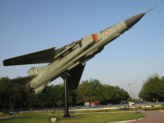
-A MiG-23MF, formerly of the Indian Air Force, on display in Gandhinagar. | Photo: Parmar uday

-The prototype MiG-23 on display at the Russian Air Force Museum in Monino, Russia. | Photo: AVIA BavARia

-MiG-23MLD formerly displayed outdoors at the USAF Museum. The aircraft has since been disassembled for restoration. | Photo: NMUSAF
#aircraft#Aviation#avgeek#airplane#mig#mikoyan and gurevich okb#mig 23#mig23#mig-23#mig 23 flogger#ussr#soviet air force#vvs#Cold War#cold war history#coldwar#flogger#Russia
140 notes
·
View notes
Text

Indian Navy officially receives aircraft carrier "Vikrant"
Diego Alves By Diego Alves 08/04/2022 - 15:00 in Military, War Zones
The Indian Navy made history by receiving the "prestigious" Aircraft Carrier (IAC) 'Vikrant' from its builder Cochin Shipyard Limited (CSL), Kochi.
Designed by the Directorate of Naval Design (DND) of the Indian Navy and built by CSL, a Public Sector Shipyard under the Ministry of Navigation (MoS), the aircraft carrier was named after its illustrious predecessor, India's first aircraft carrier to play a vital role in the 1971 war. Coinciding with the celebrations to commemorate the 75th anniversary of India's independence 'Azadi Ka Amrit Mahotsav', the reincarnation of Vikrant is a true testimony to the country's zeal and fervor in the search for capacity to increase maritime safety.
The 262-meter-long aircraft carrier has a total displacement of about 45,000 tons, much larger and more advanced than its predecessor. The ship is powered by four gas turbines totaling 88 MW of power and has a maximum speed of 28 knots. Built at a total cost of about Rs. 20,000 Crs (US$252MI), the project progressed in three phases of a contract between MoD and CSL, concluded in May 2007, December 2014 and October 2019, respectively. The ship's keel was "beated" in February 2009, followed by launch in August 2013. With about 76% of local technology, Vikrant is a perfect example of the country's search for "Aatma Nirbhar Bharat" and provides a boost to the Indian government's 'Make in India'.

The Vikrant aircraft carrier leaves Cochin Shipyard in Kochi, India, after its launch on August 12, 2013. Reuters Photo
The Vikrant was built with a high degree of automation for machine operation, navigation and survivability, and is designed to accommodate a variety of fixed-wing and rotary aircraft. The ship is capable of operating an air wing composed of 30 aircraft composed of MIG-29K fighters, Kamov-31, MH-60R multifunction helicopters, as well as advanced light helicopters (ALH) and domestically manufactured light combat aircraft. Using a new mode of operation for aircraft launch known as STOBAR (Short Take-Off but Arrested Landing), the IAC is equipped with a "ramp" for launching aircraft and a set of 'retention cables' for their recovery on board.
The ship has a large number of locally manufactured equipment and machines, involving the main industrial companies in the country. The efforts also led to the development of auxiliary industries, as well as the generation of employment opportunities and reinforcement of the return effect on the economy.
Vikrant during the tests at sea in September 2021. Photo Cochin Shipyard Limited
A major offshoot of this is the development and production of treated steel, for use on warships through a partnership between the Navy, DRDO and the Steel Authority of India (SAIL), which allowed the country to become self-sufficient with respect to the steel used on the ship. Today all the warships that are being built in the country are being manufactured with 100% local steel.
Several design iterations, including the use of 3D Virtual Reality models and advanced engineering software, have been used by the Naval Design Directorate to shape the design of the aircraft carrier. CSL has also updated its shipbuilding infrastructure, as well as improving productivity skills during ship construction.

Photo of the delivery ceremony. Photo MoD India.
The delivery of Vikrant was marked by the signing of acceptance documents on behalf of the Indian Navy by the Designated Commander of Vikrant, representatives of the Naval Headquarters and the Warship Supervision Team (Kochi), and by the President and Administrative Director on behalf of Cochin Shipyard Ltd., in the presence of senior officers of the Indian Navy and Cochin Shipyard.
Vikrant was delivered to the Indian Navy by CSL after extensive user acceptance tests carried out between August 2, 2021 and July 20, 2022, during which the ship's performance, including hull, main propulsion, auxiliary equipment, aviation facilities, weapons and sensors, as well as the maintenance and maneuvering capabilities at sea, proved satisfactory according to the test protocols and system parameters.

Indian Navy service members with representatives of Cochin Shipyard on the flight deck of Vikrant. Indian Marine Photo.
The delivery of Vikrant is the culmination of a long phase of design, construction and testing, during which the Indian Navy and CSL had to overcome a multitude of unprecedented technical and logistical challenges, including the COVID-19 pandemic and the altered geopolitical scenario. The successful delivery of the Indian aircraft carrier, in addition to an important activity and a historic event, testifies to the dedicated efforts of a large number of stakeholders in the Indian Navy, shipyard, industry, OEMs and M SMEs for more than two decades.
The aircraft carrier will soon be commissioned into the Indian Navy as Indian Naval Ship (INS) Vikrant, which will strengthen India's position in the Indian Ocean Region (IOR) by consolidating the Indian Navy as a local and global leader.
Tags: INS VikrantIndian NavyWar Zones - India/Pakistan
Previous news
Russian military satellite seems to be chasing a new U.S. spy satellite
Diego Alves
Diego Alves
Related news
MILITARY
HAL signs contract with Honeywell for the supply of engines
08/02/2022 - 14:00
HELICOPTERS
India receives first Sikorsky MH-60 "R" helicopters
07/29/2022 - 14:00
AERONAUTICAL ACCIDENTS
Indiana Air Force MiG-21 accident
07/29/2022 - 09:07 AM
F/A-18 demonstrates compatibility of aircraft carriers with the requirements of the Indian Navy.
MILITARY
VIDEO: Boeing F/A-18 Super Hornet successfully concludes operational demonstrations in India
07/20/2022 - 6:40 PM
HELICOPTERS
HAL from India marks first version flight with advanced light helicopter wheels
06/30/2022 - 6:30 PM
MILITARY
Super Hornet conducts ski-jump launch tests in India
06/01/2022 - 12:00
HOME Main Page Editorials Information Events Collaborate SPECIALS Advertise About
Cavok Brasil - Digital Tchê Web Creation
Commercial
Executive
Helicopters
History
Military
Brazilian Air Force
Space
SPECIALS
Cavok Brasil - Digital Tchê Web Creation
4 notes
·
View notes
Photo

The adoption of a memory should lead us to spend reflex in the brain act itself. We have in this case reached the automatic reflex as it is found in the dog Piraux as well as turtles Grey Walter, the perception Commander automatically action, as well as in the human reflex we know that the perception does not go to the brain: in the spinal cord itself is in fact a summary of the present and the past, its behavior depending what he sees and what he has seen. Thus it is apparent that we reproduce a model elementary artificial brain true if one was sure that at any moment the decision is a result of complex sensory impressions of this cutting and memories stored in a memory , and it is this problem that we tried to address with the fox-mail.

The anatomy of the motor is classic. Three-wheeled support it based on the model of tricycle, the front wheel is director and Driving while "taking turns" are associated with one of the rear wheels. And the front wheel is below the neck of the animal, the latter bearing at the end of an insulating support a set of bodies constituting the head of the fox. The head in question has a field of exploration of 180, demanding course that the engine is crawling with an inverter walk. The order is automatic when the head is at the end, completely turned to the right or left, or when the animal is in a period of exploration, an obstacle comes oppose the lateral movement of his head. As for the running engine mounted on the front wheel, we have chosen powerful enough because of both the relatively high weight of the fox (4 kg) than in the interest of obtaining a device with no moving too slow to that the observation is not tedious. The capacity of batteries is modest (8 volts; 6 AH), but luckily this engine running works only so discontinuous: when drilling, the total consumption of the fox is in the order of only 1 amp, and it even fewer in times of "reflection".
In this case, the basic body movements deciding fox is a "reverser system" that directs the flow of battery to the motor running or sends in a circuit where the engine is mounted exploration in series with another engine, said "character", which we will shortly explain the role. Such an inverter system is obviously controlled by a relay inserted at the exit of the posts that make up the electronic brain of the fox.
This one is fed by the circuits from the sensory organs, according to a "combination" as broad as possible impressions gathered. Admittedly, it may not be complete. Suppose that the fox advance in a certain direction and that Suddenly be an obstacle placed in his path: he must necessarily stop. This means that the tactile sense is "priority" over others. That was the formula adopted in all the past achievements. On the contrary, for the hearing and sensory impressions, it is mechanically possible for the animal to walk as well as to explore. In other words, if we consider the five senses that owns the fox, the combination may only refer to three of them, the tactile sense to be a completely autonomous circuit, while the flair we have adopted an intermediate. Such a situation is not devoid of interest: the combination of impressions from three senses is indeed a complex reproducing judgment. For example, assume that the fox track and a light comes up in a state such as a current 0.51 milliamp circulated in the relay. Accepting that this relay has been closed and it opens to a current of 0.50 milliamp, it will remain closed. The animal has "decided" to walk, but only just a little intense it will indeed be able to bring down the current plate momentarily below 0.50 milliamp, and the relay will then remain open, because for the "close "a current of 1 milliamp is necessary. The "critical areas' of his behaviour and lie around 0.50 and 1 mA, amplifiers have been resolved in such a way that these areas may correspond to" case "easily achieved in practice. In addition, regardless of the concept of judgement, we can say that the tactile sense ensures reflex, ie, as in higher organisms, the behaviour of both the fox depends reflex that acts brain. In practice, the five senses were made in the following manner: 1. The view is provided through two photo electric cells fitted with blinkers. Through this way, the sensation is not the same with a light four times more intense, at a distance twice less, as would be the case with a single cell. In other words, it can be argued that this gives to some extent the fox the perception of the terrain. 2. Hearing consists of a microphone, it is a rudimentary model, but sensitive, with a pellet shot at using the current Battery and feeding a transformer coupled to an electronic amplifier. 3. A sense of direction is represented by a potentiometer housed in the neck of the animal. He then brought to the polarization of a certain lamp L ', while the sight and hearing are ordering the lamp L, the main one being sensitive relay inserted in the circuit plate Joint L and L'. We see that this assembly performs well a combination of three types of sensory impressions so far considered. 4. The touch is ensured by the papillae tactile housed in the head, the animal it is that close contacts as soon as a body outside touch this head. The contacts in question were inserted into a circuit directly controlling the inverter system. 5. The flair is a metal plate which forms the nose of the fox, the principle being that the papillae capacitive raised about Miso. The Capacitor they excite a relay special command that may act on the reverser system like the taste of contact, but this relay is also linked to the "post character." [Note RH – This is the so-called “sense of smell” – not real smelling at all.]

THE MEMORY AND CARACTÉRIEL INTEGRATIVE However, under the previous scheme we have not yet seen the memory integrative, element number 1 of the Act cerebral. Note well what fundamental difference between memory and integrated memory simple, commonly known recording. This formula corresponds to the recording of a sequence of signals on any media, as a result of which there will subsequently recover from this simple scroll which we find illustrated both with the wire with the conventional magnetic disk phonograph. Instead, the memory is a true integrative synthesis of memories: one can, in this case, imagine under the appearances of a surface initially plane, in which the various events just make as many small deformation. Thus all the events in which man has witnessed since its birth as they mark his mentality can be achieved by the appearance of its surface mnémique as a result of all its strains, each of which has been forgotten in detail. Thus with the character that we tried to reproduce such a principle integrative memory. It is, as we have said, with an engine of exploration, and so is likely to be turned on whenever the sensory impressions of fox reach the threshold of excitement that toppled the regime reverser. This engine is in this case coupled with a knob that controls the voltage of the grid auxiliary tube '. If this tension is very high, the current passes through L ', even though the main gate is biased negatively. Instead, a low voltage of the auxiliary gate has the effect of blocking L '. Through this mechanism, it appears that the sensory impressions at the same time they control the movement of foxes change the setting of its amplifiers, ie, faced a similar situation, his behaviour is not the same from one day to another, since the fox has "lived" in the meantime. However, we felt it appropriate that this character is not turned on at all times. To this end, we did it depend on a command post capable of short-circuiting. He makes himself the synthesis of several phenomena, it depends on three contacts controlled by the movement of the character itself (which means that, in itself, the character hangs at the end of a time Operating determined), by the movement of fox (an inverter is controlled by the rear wheels), with the relay of Inductor. When the character is action, the sensitivity of the fox is changed, and we can say that it is varied. On the contrary, when it is short-circuited, the character is fixed, or at least can no longer mention that "variations in mood," according to the voltage of the batteries. This tension, which directly controls the polarization of light ', is indeed a function of the state of discharge of batteries that the energy required by the engines and various windings. If the decision by the fox to a given situation represents a synthesis of the present and the past, it should be noted that the "weight" of the past is variable depending on the position of the head. We have in fact indicated that the movement thereof acts on a potentiometer commander lamp L ', the sensitivity of the tube being so great when the head is right, and on the contrary low if the head is completely turned to the right or left. Similarly, it appears that, depending on the individual, the burden of the past is more or less depending on their temperament all levels with the possibility of hedonistic while the contemplative, for a given individual, the part of the past also varies depending on the circumstances. So when the fox look straight ahead, can we say he lives primarily on his memory, especially as he takes on his perceptions when his head is turned. A DISCONTINUITÉ OF PERCEPTION Worth noting simply, without discussing this issue here, we wanted to introduce a cell of imagination in this fox, as he speaks for binary through two bulbs green and red respectively worn by her head. But above all, we tried to reproduce a further analogy with the human brain by adopting the principle of a perception discontinuous, this discontinuity is of a paramount importance to us, In this case, our brain can be considered as a working machine in a vacuum, except during short intervals which are repeated at a rate of 10 to 12 per second, during which information is collected specifically in our cerebral areas. Moreover, this rate though we explained our eye sees the images if they succeed because of Brettermeier per second, while over a dozen is the cinema, and similarly our ear perceives sound if noises successive obey a similar law. In fact, it is neither our eye or our ears that need to be blamed, but rather the brain, the latter taking cognizance of the world in order to change discontinue its work in the light of new information received. To achieve such a discontinuity in the fox, we have called these comptetours "solidarity" with a rear wheel, which he had previously discussed. Thus, a contactor primary is closed all three rounds, which blocks a relay memory likely to be released only if a cause affects the movement of the head. On the other hand, a contactor school is closed all six rounds. However, the closure of these two contacts has the effect of bringing Engine exploration and character, while everyone's perceptions are cut, this state of affairs remaining until one of the two contacts is open. This happens in practice if the head hits an obstacle side or, at the end of the course, ie when the head turned completely on the one hand, is required to change its sense of exploration. At that moment, the fox sees the outside world with a new spirit, as we pointed out that it is precisely at the end of the race that the weight of the past is minimal …

If the fox claims reproduce the basic characteristics of cerebral work, understand that it is a "model" Basic reduced, both at the perception that the trial: two photo electric cells appear in effect Accessories well as poor against the 140 million cell door as our retina. And on the other hand, it is assumed that our brain has about 10 billion neurons! As such, there is no doubt that we have barely glimpsed the fantastic opportunities that lie ahead. And indeed, in the past, many manufacturers have shown us automates all the subtlety of behaviour that may be expected from a machine if you have the patience to develop it accordingly. The prestigious name of Vaucanson is there, with its wonderful machines: if we consider only a "wing" of the famous duck, we must not forget that it incorporated elements 400, while the same Vaucanson knew how to build representation " Cleopatra "Marmontel a snake that s'élançait across the stage whistling and went with astonishing precision drill with the queen. And manufacturers automata unaware that agent wonderful electricity soul of sensory organs and today's engines! One might ask what machines they would have done with the resources of modern electronics. In fact, the technique we now enter an era of genuine "electronic watches" where one can build tubes the size of a pea, before tomorrow transistors big as a phonograph needle. In the electric shows, we can see no other an electric motor and a battery offering 1 single aspect of pellets? Under this sign, it is hoped to build tomorrow's electronic brain the size of a human brain, ie true miracles are to be expected in terms of electronic animals, beyond which our current DIY appear in a Poverty disconcerting. As to the desirability of such animals artificial, it seems considerable. First theoretical usefulness is real, real machines analogies allowing us the most interesting studies on the functioning of our nervous system. Importantly, we believe qu'inéluctablement, besides calculating machines and electronic brains ever more complex over which man relies more and more to solve a growing number of operations intellectual grounding peuplera tomorrow ' a large number of robots that are able drive: extending the wording of these artificial animals, they represent a people capable of slaves' to perform all tasks material which man will hear the charge, under the species of The most diverse races …

2 notes
·
View notes
Text
Affinity at serangoon floorplan
The Light Controllers advertise report spotlights on the Outbreak Impact examination of key focuses affecting the development of the market. The insight report arranged contains subtleties on the main players of the Global Light Controllers Market, alongside different depending viewpoints related and connected with the market. Profile the Top Key Players of Light Controllers, with deals, income and worldwide piece of the pie of Light Controllers are broke down determinedly via scene complexity and address data. Upstream crude materials and instrumentation and downstream interest investigation is https://www.affinityatserangoon.com.sg/balance-units-chart/ furthermore administrated. The Light Controllers advertise business improvement patterns and selling channels square measure examined. Light Profiles, Gross, Gross Margin, Capacity, Product Picture and Specification, Production, Price, Cost, Revenue and contact data. Controllers industry inquire about report improved on overall rivalry by highest prime makes which giving data, for example, Company

Our investigation experts intensely find out the noteworthy parts of the worldwide Light Controllers advertise report. It additionally gives a top to bottom valuation with respect to the future progressions depending on the past information and current condition of Light Controllers advertise circumstance. In this Light Controllers report, we have explored the principals, players in the market, geographical locales, item type, and market end-customer applications. The worldwide Light Controllers report involves essential and auxiliary information which is exemplified as pie plots, Light Controllers tables, investigative figures, and reference graphs. The Light Controllers report is introduced in a proficient manner that includes essential tongue, fundamental Light Controllers framework, understandings, and certain realities according to comfort and appreciation.
The exploration approach that has been utilized to figure and gauge the worldwide Light Controllers advertise comprises of essential and optional research strategies. Key examinations incorporate nitty gritty meetings with chiefs, CEOs, officials and legitimate workers, for example, VP.
Income, deals, esteem, limit, territorial statistical surveying, segment sagacious data and market gauges incorporate innovation development situations, customer conduct and end-use patterns and elements, and creation limit is considered. Market development was determined by allocating various loads to these parameters and assessing market sway utilizing weighted normal investigation.
Report Hive Research conveys key statistical surveying reports, factual overviews, industry examination and gauge information on items and administrations, markets and organizations. Our customers ranges blend of worldwide business pioneers, government associations, SME's, people and Start-ups, top administration counseling firms, colleges, and so forth. Our library of 700,000 + reports targets high development developing markets in the USA, Europe Middle East, Africa, Asia Pacific covering businesses like IT, Telecom, Semiconductor, Chemical, Healthcare, Pharmaceutical, Energy and Power, Manufacturing, Automotive and Transportation, Food and Beverages, and so on. The Toh Tuck street townhouse site was all the rage during the dispatch of government land deals in the second quarter of 2016. Envisioning the upswing of Singapore's land showcase, it pulled in an incredible 24 eager for land engineers to take an interest in the offering with Malaysian designer SP Setia developing champ.
1 note
·
View note
Photo


First Look: The Track-Only Ford GT Mk II
Ford and Multimatic revealed at the Goodwood Festival of Speed the Ford GT Mk II, a limited-edition, track-only GT that represents the next stage in Ford GT performance.
With a 700 horsepower 3.5-liter EcoBoost engine, race-proven aerodynamics and competition-oriented handling, the GT Mk II has been co-developed by Ford Performance and Multimatic based on competitive learnings from Ford’s successful FIA World Endurance Championship and IMSA WeatherTech SportsCar Championship campaigns with the Ford GT race car yet GT Mk II is engineered independent of race series rules, regulations and limitations.
Limited to just 45 vehicles, with a starting MSRP of $1.2 million, the GT Mk II joins the 2016 24 Hours of Le Mans winning race car & the Ford GT supercar.
Built in Markham, Ontario, the Mk II begins life at the main Ford GT plant before being transferred to a specialist facility at Multimatic Motorsports where it is crafted into the Ford GT Mk II.
The Best of Both Worlds
The Ford GT Mk II is focused around aerodynamic and engine improvements and shares key features with both the street-legal GT supercar as well as the GT race car. Many of its components have been track-proven in the world’s most challenging endurance racing events.
The large dual-element rear wing exceeds what the Ford GT race car offers in terms of downforce. An all-new front racing splitter and diffuser have been incorporated along with new fender louvers and dive planes, which help balance out the extra rear downforce.
These aggressive aerodynamic changes enable the GT Mk II to generate over 400 percent more downforce than the Ford GT while fixed aerodynamic elements along with its race-proven suspension and Michelin Pilot Sport racing tires enable the car to pull more than 2Gs of lateral grip.
GT Mk II is also lighter and more agile. The street car’s adjustable ride height and drive modes have been removed, providing a weight savings of over 200 pounds while 5-way adjustable DSSV shock absorbers work with a lowered and fixed ride height to improve handling and keep the Mk II as aerodynamically efficient as possible.
The Ford GT Mk II features the 3.5-liter EcoBoost engine that powers both the Ford GT race car and the road car but since the Mk II is not limited by any racing sanctioning body it is able to generate 200 horsepower more than the race car, making the Mk II the most powerful version of the Ford GT. The 3.5-liter EcoBoost is paired with the same seven-speed dual-clutch transmission from the Ford GT but specially calibrated for this track-exclusive application.
To add stamina to power, the GT Mk II adds innovative engine cooling technology, including a high capacity air-to-air outboard mounted charge air cooler with water spray technology. The water spray automatically activates in high temperature situations to provide cooling by applying atomized water on the charge air cooler allowing the Ford GT Mk II to maintain a consistent level of power at high temperatures.
A roof-mounted intake reminiscent of the race car engine air intake has been added for the Mk II to feed auxiliary engine, clutch and transmission coolers, giving the Mk II optimal cooling for the most extreme track day duty.
Increased engine power is paired with improved stopping power. The Mk II features braking performance beyond that of the GT race car by utilizing the street car’s carbon ceramic brakes, including 15.5-inch front and 14.1-inch rear Brembo brakes. Unique forged aluminum 19-inch wheels cover the massive brakes with race-proven Michelin Pilot Sport GT tires.
The front fascia and hood of the Mk II are similar to the street car as well as the stylized Ford GT headlamps with signature running lights.
Interior changes include a bespoke Sparco racing seat with a six-point racing harness and an optional passenger seat. A full MoTeC data acquisition system has also added to provide vital information for a track racer, which also doubles as a display for the rear camera.
Latest GT Family Member
The Ford GT production car, which made its first Goodwood appearance in 2017, is the most advanced and exclusive Ford road car ever, limited to volumes of no more than 250 a year, globally.
Built for the 24 Hours of Le Mans endurance race, the Ford GT race car has been a great success for Ford, winning the GTE Pro class at Le Mans on its first attempt in 2016, exactly 50 years on from the first of four successive Le Mans victories for the Ford GT40 at Le Mans.
Ford ended its competitive GT racing program in the FIA World Endurance Championship at the 2019 Le Mans in the GTE Pro class. The Ford GTs will continue to race through the remainder of the IMSA season which culminates at Road Atlanta in October.
The GT Mk II makes its public debut running in the Supercar class at the Goodwood Festival of Speed and will be sold directly to customers by Multimatic.
#track cars#cars#supercars#ford#Ford GT Mk II#goodwood#usa#american#goodwood festival of speed#first look#news#200#ford gt
260 notes
·
View notes
Text
Past of the future, future of the past...
Chapter 7. Never the same. "Entering Hoenn airspace!" announced the navigator. "Current speed - 100 km/h, altitude - 10 km." "Coolant temperature… normal," added mechanic. "Reactor’s working at optimal capacity. Main propellers rotating at 300 rpm, blades angle set at position 4." "Good," responded the captain, looking in the front window. "Rad-scans?" "I think directed rad-scanners are picking up something in the Meteor Falls… looks like our target," said the radiation safety officer. "Pilot - drop us down to 3 kms and lower the speed to 30 km/h. When we'll be directly above the Meteor Falls - shut down the primary propulsion and deploy the auxiliary thrusters, then transfer the control to me." "Acknowledged, commencing corrections," replied the pilot, slightly shifting joystick and thrust control rudder. "Good," noted the captain, then relaxed a bit. Right now, they were escorted by a few of military helicopters, tiltjets and some Hoennian military Pokemon, just in case anyone gets the wrong idea upon seeing such a great airship. After all, it was equipped with a nuclear reactor for power source and, should the rest of the airship be destroyed and the ultra-durable protective shell breached, will cause a lot of contamination… ---- "Your Majesty… your Majesty..." a scientist in Zemlino carefully tried to wake up the Emperor, who was sitting asleep in the chair near the ORBCOM station, after all those crazy events of yesterday. "Hm?.. If there's a third moon around the Red Planet - notify the Team 37, especially if it turns out to be an… eyed balloon or something…" the Emperor replied without actually awakening, being, apparently, in the midst of some bizarre and adventurous dream. "Again…" the Empress, who has just recently arrived to the flight control center, sighed, knowing a bit too well, just how enthusiastic her husband could get about anything aerospace-related. Especially after the first manned flight, when he has, somehow, managed to get into the SP-04 "Black Bird" spaceplane and, therefore, become the first human in space... "Anyway… now with the "Red Explorer" around the Moon, "Hauler" preparing to deorbit and "Dreamwing" back in hangar… we need to decide, how to direct the space program," said director of Zemlino FCC. "During the last nine months, it was directed solely towards building and launching the nuclear pulse battleship to open the road towards the skies again, with a few resupply vessels for it, but now, once we did it and made our intentions on keeping it open clear… what do we do?" "Honestly…" Empress started, in uneasy voice, "... I don't know. I mean, yes, we've opened the road to space again and people of the Empire are very happy about that, as well as showing Nation, that we're no jokes, but… I'm not really sure, what kind of directions are to be made of greater priority." "Orbital factories," Emperor replied, waking up upon hearing it at once. "Factories? Well… yes, they can be of use, but…" began director, only for the Emperor to interrupt him: "No buts. Even though I'm not big at ruling, I think we should capitalize on our success and get the info about the materials, which can be produced only in microgravity, and how they can help to improve the lives on the ground. I think info about the orbital hospitals can also help, since they are something everyday human can understand. If they start telling, that it'll be only available to aristocracy and rich - we should capitalize on grandiosity of our new Integrated Program Plan. It's finally time to put it back into action and make it reality." "... I guess," sighed Empress, thinking about words of her husband. "No time for guessing. We must make them realize, that the only way for them to get access to all the cool space stuff is to support the space program and help it grow as never before. We're on the verge of greatness now and we must achieve it." "Hopefully, you succeed at this," said director of the FCC, "because I'd hate the program falling apart, after all we've done..." "We all would," replied the Emperor and the Empress at the same time. ---- "So… that's it," murmured Damien, seeing gigantic nuclear-powered airship soar through the skies back to Soris, carrying highly radioactive corpse of Rayquaza inside the shielded cargo section. For all of the Draconid People, it was one heck of a blow - not only the Dragon Lord was killed, but they could not even bury it properly, having to allow sorisians to stuff it into an underground nuclear waste dump. And, what's worse, none of them could do anything about it - not only Rayquaza's corpse was radioactive enough to be able to give human a fatal radiation poisoning in matter of a few minutes, burying it in classic way would've allowed the leaking isotopes to, eventually, contaminate the groundwater and cause a big ecological catastrophe. "Grannie…" started Helian, "... What will happen now? With no Dragon Lord?" "I don't know," said the Elder, looking at the airship too. "But I think, that the world will never be the same…" ---- "So, we're done with preliminary checks," sighed mechanic, who was servicing the "Dreamwing" in the hangar #2 of Zemlino Space Center. "So far, everything looks fine." "Great," replied commander of the spaceplane. "Hopefully, our birdie will stay fine in the future too." "Hopefully… but it may get replaced with the new nuclear-powered spaceplane soon, when they iron out the hiccups of nuclear turboramjets and aerodynamics of the aft. I've heard Emperor got opposed to the idea of jettisonable aerodynamic tail cone and they're busy developing something, which will allow everything to come up and down in one piece." "Cool. Almost like our machine." "Yeah. From what I've heard, test flights of the SPN-01 "Blizzard", the first BLUEBIRD spaceplane, should start pretty soon. And with no Rayquaza around, they should be safe enough." "Safe, you say… the debris is still in place, though. And I don't think, that this spaceplane can be as armored as the battleship we've launched recently." "Well… yeah. Still, we've managed to take a flight to the "Red Explorer" and spend some time up there, so, maybe it won't be as bad. Besides, I've heard some rumors about how there are plans for dual-purpose weaponized satellites, which can both destroy targets in space and use their weapons for clearing space junk." "Hm… Interesting and kinda makes sense. I guess those laser researches in the ISFs 5 and 9 will be put to good use, after all." "I guess." "Hi, guys," said the engineer of the "Dreamwing", approaching the two men on this catwalk. "Anything wrong with sensors?" "No, nothing is wrong with them," replied mechanic and was a bit surprised upon seeing, how crewmembers of the "Dreamwing" suddenly got grimier and exchanged looks of understanding. "I guess we may have another dragon problem soon enough…" stated the commander, looking at the machine. "And who knows, if we'll have to resort to warships again…" ---- Awake. Alive. Those were the first thoughts of the young dragon. Right now, it did not understand the situation yet, but some strange memories, belonging both to the dragon and not to it at the same time, were flooding its mind. It was slowly to understand some things, but not too fast. It understood, that its name was Rayquaza, the Sky High Pokemon. It understood, that it exists to protect the skies and deal with Groudon and Kyogre. It understood, that something must've happened to its predecessor, if it was awakened right now. With those thoughts, young dragon has struck the hard shell of the egg and broke it apart, freeing itself. As it has just remembered, despite most of the Legendaries, like itself, being near-immortal, there were still contingency protocols in events of something exceptional happening. And, apparently, something exceptional it was. The young dragon has remembered the last moments of the old dragon, when it fought some huge cone-cylindrical metallic construct and, somehow, was struck down by it. Whatever moves this construct was using, they've had near-infernal power. And young dragon could not allow itself to suffer the fate of its predecessor. For now, it will lay low and explore, as it grows back to the power level of a full Legendary. Then… it will depend on circumstances. With those thoughts, young pitch-black serpentine dragon took off, flew past the obstacles and left the cave, well-hidden in the mountain range. Right now, it had to, first and foremost, survive and grow up. ---- Inside the bridge of the huge sorisian airship, there was not much action now. Rayquaza's highly-radioactive corpse was now in the reinforced storage, they were en route home, everything on the airship worked perfectly… honestly, it was kind of boring. "Guys…" started the navigator, "Do you remember our first assignment? The aerial expedition to Alola?" "Oh, I sure do!" replied the pilot, shifting in the chair a bit. "How we all have flown to it, how we've spent a decent amount of hydrogen burnfuel for our recon plane and heavy-lift helicopter, how technicians were able to assemble the mooring masts in just three days… that was the time!" "Especially with how we've managed to bring some Flygon eggs to Soris. Who knew, that those insect-dragons will become so popular at our home!" "Well… they did become popular with our colonists, didn't they? I mean, by the end of our stay there, quite a few people liked their partner 'Spirits of Change'. Including you." "... Yeah. Also…" With those words said, pilot reached out for one of his MFDs, quickly selected "security camera feeds" options and looked at the feed from the top hangar a bit. In it, an insect-dragon was quietly sleeping, curled near the tandem-rotor helicopter - much like during their return from the expedition. "... Nah, she's fine. Took Sunny form for some reason, though." "I would've said because of our cargo, but it'd be stupid. By the way… strangely enough, but native Alolan Flygon seem to be extinct nowadays, with Hoennian subspecies, somehow, having replaced them." "Hoopa's shenanigans again?" "Likely. May also be combined with the fact, that Hoennian Flygon, while lacking the sheer versatility of its Alolan progenitor, is better adapted to the desert conditions. I guess they've just lost the competition there." "And our region has preserved those dragon-bugs. Cool." "I guess. I've heard from some of my friends in ISF 4, that some scientists from Hoenn and Alola would be really happy to get more data about the extinct-for-them Alolan Flygon." "Likely." Author's notes: ISF - Imperial Science Facility. ORBCOM - Orbiter Communicator. MFD - Multi-Function Display. Sorisian nuclear airship is based on that. BLUEBIRD spaceplane is based on the real M(G)-19 "Gurkolyot". Alolan Flygons are based on that wonderful picture.
1 note
·
View note