#BNC compression tool
Explore tagged Tumblr posts
Visit Tumblr Blog
Explore Tumblr blogs with no restrictions, modern design and the best experience.
Last Seen Tumblr Blogs


Fun Fact
Tumblr has 4 main sources of revenue.
Text
https://www.futureelectronics.com/p/interconnect--connector-tools-contacts-accessories/1062-16-0144-te-connectivity-2076061
Wire cable assembly, Crimp tool, BNC compression tool, Ethernet cable
1062-16-0144 14 - 18 AWG Size 16 Gold Plated Crimp Socket
#TE Connectivity#1062-16-0144#Connectors#Tooling and Accessories#Crimp tool#BNC compression tool#Ethernet cable#USB#Compression tool#Interconnect contact#cable crimper#Wire Connector#Crimp Socket Contact#Connector contact#Ethernet
1 note
·
View note
Text
Ask The Videoguys - Tech Advice and Top Tech Tips from the Videoguys - Videoguys
New Post has been published on https://thedigitalinsider.com/ask-the-videoguys-tech-advice-and-top-tech-tips-from-the-videoguys-videoguys/
Ask The Videoguys - Tech Advice and Top Tech Tips from the Videoguys - Videoguys

On this weeks Videoguys Live, James hosts Ask the Videoguys where he will give Technical Advice for your production as well as sharing our Top Videoguys Tech Tips. James will share tips on frame rates/bit rates for live streaming, differences between 3G, 6G, & 12G SDI, finding the IP address of NDI PTZ Cameras, setting up a REMI production, differences between RAID 0, 1, 5, & 6, on the go storage solutions, and more!
Watch the full video below:
youtube
What streaming resolutions/frame rates do different CDNs recommend? What bitrate should I use?
Platform
Resolution
Compression
Bit Rate
Facebook
1080 60p
H.264
4.5-9mbps
YouTube
4k 60p
H.265/H.264
10mbps/35mbps
1080 60p
H.265/H.264
4mbps/12mbps
LinkedIn
720 30p
H.264
3.5-6mbps
Tech Tip: use the highest common denominator for resolution and frame rates when streaming to multiple destinations if your encoder doesn’t allow different settings
What is the difference between 3G, 6G and 12G SDI? And why would I choose SDI over HDMI?
3G SDI – Up to 1080 60
6G SDI – Up to 4k 30
12G SDI – Up to 4k 60
SDI Pro SDI Con HDMI Pro HDMI Con Long Cable Run Can Cost More Inexpensive Short Cable Run BNC Locking Mechanism Need to know if it’s 3G, 6G, or 12G Common No Locking Mechanism 4K 60 through a standard cable
Tech Tip: Consider using AV over IP as it is the best of both worlds giving long cable runs, on a common cable with a locking mechanism!
How do I find the IP address of my NDI PTZ camera and change it to either DHCP or Static?
Download NDI Tools
Open NDI Analysis
Plug camera into network
Run the “NDIAnalysis.exe /find” command
Find the IP address of the desired camera
Plug in external Network Adaptor to computer
In Network settings on computer change Network adapter settings to be on the same range as the camera
Select “Change Network Adaptors”
Right click on USB Ethernet
Select “TCP/IPv4”
Change Ip address to be same range as range from NDI Analysis
Plug camera into network adaptor and turn on camera
Now you can access the cameras web gui to change camera settings to DHCP or a Fixed Ip of your choosing
Once DHCP or Static is selected, unplug the camera and plug into Network Switch
For complete Remi control, what products do you recommend starting with?
PTZOptics Hive Studio
BirdDog Cloud
Epiphan Connect
NDI Bridge
LiveU Studio
Now Is the Perfect time to get into Remote Productions with so many workflows!
What is the difference between Raid 0, Raid 1, Raid 5 and Raid 6?
RAID 0 (Striping): Data is stored evenly across the number of disks in the array. This process is called disk striping and involves splitting data into blocks and writing it simultaneously/sequentially on multiple disks. It provides improved performance but no redundancy
RAID 1 (Mirroring): Data is duplicated and stored on each drive. This process is called mirroring, and it ensures you won’t lose your files if a drive fails. It provides redundancy but no performance gain
RAID 5: Uses disk striping with parity. It sets aside “one drive’s worth” of disk space for parity data. RAID 5 requires fewer hard drives but can provide protection against a single drive failure
RAID 6: Similar to RAID 5 but introduces dual parity. It sets aside “two drives’ worth” of disk space for parity data. RAID 6 can provide protection against two simultaneous drive failures
What is the best storage system for storage on the go?
Definition: Portable rugged SSD drives are high-capacity, high-speed storage devices that are designed to withstand harsh conditions.
Use Cases: Ideal for outdoor use, travel, and situations where data might be exposed to rough handling or environmental hazards.
Advantages: They offer the speed of SSDs, combined with a design that is resistant to shock, dust, and water.
We can help you find the perfect drive for your on-the-go needs, whether it’s waterproof, dust proof, shock proof or all of the above
#4K#6G#Advice#amp#Analysis#Best Of#bridge#Cameras#change#Cloud#command#compression#computer#data#Design#devices#dhcp#Difference Between#dust#Environmental#Facebook#Full#Giving#gui#hazards#hdmi#Hive#how#it#LinkedIn
0 notes
Text
0 notes
Link

The CP-321 adjustable compressoin tool crimps most connectors (F, BNC, RCA on RG59, RG5 and RG11 coaxial cables). Quick and reliable tool for compression connector installation. More Details visit : https://totaleclipse4u.com/default/cp-321.html
0 notes
Text
Connector Compression Tool Crimper for RG6 RG59 F BNC RCA Coax Cable
Connector Compression Tool Crimper for RG6 RG59 F BNC RCA Coax Cable
$1.70 OFF for Adjustable Posture Corrector Back Support Brace Belt!Only $16.65!
You need to use promocode. The discount is available only for certain category. There is no minimum order value. The promotion is available for all customers of the store.
2 $ OFF Start date: 07/02/2018 End date: 31/03/2018

CAZ572W
Grab Now
Get Your Cash Back Offer
0 notes
Text
Computer Network Cabling
Network Cabling and Installation https://www.itccablingandcameras.com/
Have you ever wondered what it is that connects computers and networks to one another? Network cable in conjunction with the associated hardware (network switches, hubs, demarcation equipment) is responsible for computers being able to connect and transfer data across intranets (internal network) and the internet. Network cabling today is used for many other purposes besides computer networking. It can be used to carry video for security camera systems as well as video for cable TV and AV (Audio/Visual) applications. Network cabling is also used as control cable in Building Maintenance Systems and Access Control Systems. There are several different types of cables that are used for this purpose, including unshielded twisted pair, shielded twisted pair, fiber optic and coaxial. In some cases, only one type of cable is used in a network, while in other cases, many different types are used. Wireless systems are becoming more and more popular but always remember you still need network cabling for the wireless system. There is still two things that make network cabling better than a wireless network: it is much more secure and reliable.
Understanding Cable Type
Before you can really understand how cable networking works, you need to know about the various cables and how they work. Each cable is different, and the type of cable used for a particular network needs to be related to the size, topology and protocol of the network. Here is a rundown of the cables that are most commonly used for network cabling:
Unshielded/Shielded Twisted Pair - This is the type of cable that is used for many Ethernet networks. There are four sets of pairs of wires inside the cable. There is a thick plastic separator that keeps each pair isolated through the run of cable. Each pair of wires are twisted so there will be no interference from other devices that are on the same network. The pairs are also twisted at different intervals so they will not cause interference between themselves. In an application where there is a lot of Electromagnetic Interference (EMI), such as a mechanical space, you may choose to use shielded twisted pair, which has an outer shielding that adds extra protection from EMI. Category 5e, 6, 6A and 7 are the general choices today. Twisted pair cable is limited to 295' on a horizontal run. Twisted pair cable is used for many applications. Standard station cabling for computers and VOIP phones, wireless access points, network cameras, access control and building maintenance systems are just a few. This is one of the most reliable types of cables, and when used, network failures are less common than when other cables are used.
Fiber Optic - Fiber optic cable is primarily used as backbone cable although it is being used more and more as station cable (think FIOS). By backbone cable I mean it connects Telecommunication Rooms within a space to each other. Fiber optic cable has huge broadband capacities which allow it to carry large amounts of information as super fast speeds. Fiber cables can cover great distances(hundreds of meters) as opposed to copper cable. Because these cables must work so hard and the information travels such distances, there are many layers of protective coating on fiber optic cables. Fiber cables transmit light as opposed to electrical current. Fiber optic cable requires much less power than high speed copper does. Fiber optic cable is a great choice for high speed reliable communications.
Coaxial Cable - Coaxial cable usually falls under the scope of work of the network cabling installation contractor. Coax will be used for the cable television locations within the space you are cabling. The service provider will drop off the outdoor cable at the point of entry. The contractor will run an extension (usually RG-11) to the local telecom closet within the space. The individual station runs(RG-6) will terminate on a splitter to connect to the service cable. The center of this type of cable has a copper conductor and a plastic coating that acts as an insulator between the conductor and the metal shield. This cable is covered with coating, which can vary in thickness. The thicker the coating, the less flexible it is going to be. There are a few types of terminations for coax. Compression, crimp and twist on are the three types of terminations. The best method is compression as long as they are performed correctly. Crimp terminations are also reliable and require the right tool for the particular connector you are using. I would not recommend twist on as they are not reliable and prone to problems. A few types of coax connectors are F connectors, BNC connectors and RCA connector.
Network Cabling Components
Patch panel - This is the panel where all of the station cables terminate within the Telecommunications Room. They are usually mounted on a wall mount or floor mount telecommunications rack. Typically there are 24, 48 or 72 ports on a patch panel. There are a few different styles such as angled or straight. Panels also have the option of having the 110 type pins attached to the back of the panel or you can terminate jacks and snap them into the empty panel.
Data Jack - This is the connector where each individual cable is terminated out at the station side. The jacks are snapped into a faceplate ranging from 1 to 8 ports typically. Data jacks can be terminated in a 568A or 568B pinout. Check with the customer or designer for the correct pinout.
RJ 45 Connector - The RJ-45 connector is installed on the end of a network cable. They are 8 pin connectors. The most common place to find the RJ 45 is on a cable terminating at a wireless access point. The RJ 45 is a male connector and would plug into the port on the WAP.
Wireless Access Points - These are devices that transmit network access wirelessly. Typically they are mounted on the ceiling or wall. A wireless survey would need to be performed to maximize the correct placement of WAP's. Contrary to popular belief wireless devices STILL need to be fed with network cabling.
Cable Supports - (Commonly called J-Hooks) Cable supports are mounted in the ceiling as a support structure for your cable bundles. Main path cable supports should be mounted to the concrete deck ceiling within the space. You are no longer permitted to hang j-hooks from ceiling supports, electrical or plumbing pipe or any other system infrastructure.
Wire Managers - Wire managers are installed between patch panels and switches to manage patch cables. They serve a very important purpose as they keep law and order in a Telecommunications Room. Nothing irks me more than finishing a brand new beautiful install and having the IT group come in and not use the wire managers. It ruins the aesthetics of the job. In addition it sets a bad precedence from the birth of the Telecommunications Room that others are sure to follow.
Firestop Sleeves - Firestop sleeves are a vital part of any network cabling installation these days. Gone are the days of just banging holes into sheetrock and passing cables through. When you penetrate any firewall on a job you must install a firestop sleeve. There are specific products made for this. EZ Path and Hilti both make excellent versions in varying sizes. You can install a sleeve of EMT pipe through a wall also as long as you use firestop putty or firestop silicone to seal off all openings. This can save lives and minimize damage in the event of a fire.
Cable Labels - All cables and termination points should have a unique label. This makes installation, maintenance and troubleshooting much simpler. For a professional all labels should be computer generated. Hand written labels are just not acceptable today.
Network Cabling Installation
Network cabling installation drawings should be designed by a BICSI certified RCDD (Registered Communication Distribution Designer). There are a few things that need to be considered.
The type of cabling solution to be implemented - The cabling vendor or customer will need to select a solutions manufacturer. Siemon, Leviton, Ortronics and Panduit are some of the more common choices. The type of cabling solution will need to be discussed. Cat 5e, Cat 6, Cat 6A or Cat 7 are the copper types of network cables that can be offered. The style of the racks, data jacks, faceplates, patch panels and wire managers will also need to be discussed and chosen. Make sure this is done early as lead times can be long for certain manufactures and styles.
The location of the network equipment and racks - The room where they are housed is commonly referred to as MDF (Main Distribution Frame) Data Room, Telco Room or Telecommunications Room. All cables runs need to be within 100 meters. If cable runs are going to be over 100 meters you will need to add a second Telecommunications Room. This is also called an IDF(intermediate Distribution Frame). The IDF will often need to be connected to the MDF via fiber optic backbone cabling. The MDF will house the service provider feed from the street, which will feed the network. Typically you will also find security equipment and access control equipment here. It is a better design to have all the low voltage systems housed in one location. Measure all equipment and racks that will be required based on cabling quantities. Include access control, security, electrical panels and air conditioning units. The room needs to be large enough to accommodate all equipment.
The pathways of the cable trunks above the ceilings - Cable paths need to steer clear of electrical light fixtures or other sources of EMI (Electro Magnetic Interference). Keep cable paths in accessible areas of the ceiling for future cable runs and ease of maintenance. All paths should be run above hallways or corridors and cables enter individual rooms on sweeping 90 degree turns. Install a firestop sleeve or putty for all penetrations of a fire wall. Be careful when pulling cables so as not to bend them beyond their bend radius. This will cause a failure when testing. DO NOT tie cables to ceiling hangers or sprinkler pipes. They need to be tied at least every 5' on horizontal runs, and even more on vertical runs. J-hook supports should be anchored to the concrete deck above. Use velcro wraps every 5' or so when finished running cable to give your cable bundles a great looking finish.
Terminating Network Cabling - When terminating cable make sure to check the floor-plan numbering to each cable label to make sure the cables are in the correct spot. If something is not matching leave that cable on the side to be "toned out" later on. Use a cable stripping & cutting tool to get a uniform cut on the cable jacket and to be sure you won't nick the copper conductors inside. Always keep each pair twisted as tight as possible right up to the pins where you terminate the cable. This will ensure you won't get a NEXT or Return Loss failure. Before you start any terminations inquire weather the pinout will be 568A or 568B. This will determine which order the conductors are terminated in and is very important before you start. All cables should be dressed nicely and uniform. The project manager should make a termination chart of the patch panels for the technician that will perform the terminations. This will show the back of the patch panels and where each cable gets terminated with it's label number.
Testing your network cabling - There are a number of cabling testers out on the market. The tester we prefer to use is the Fluke DTX-1800 Cable Analyzer. This is an amazing tool. It will give you a detailed report of each cable that is tested. It tests for wiremap, insertion loss, NEXT, PSNEXT, ACR-N, Insertion Loss and many others. The best part about these new age testers is their troubleshooting skills. The Fluke will tell you where a cable is damaged and which particular conductor is damaged. If you terminated a pair out of sequence the tester will tell you which pair and on what end the error was made. The Fluke does everything but fix it for you! Most clients want to see verified test results. The new testers will provide cleaned up PDF files of the test results. These can be emailed directly to the client.
Hopefully this guide has helped you to better understand the complete system of network cabling. It is an ever changing field and we need to keep up on the latest technology to stay ahead of the curve and offer our clients the best cabling solutions. Please add your comments, suggestions or questions. Please sign up to our email list for the latest cabling news and our shared experiences from the field. You will also receive special offers on future training products before they are released. Thanks for your support.
Please visit http://www.networkcablingworld.com, the premier website for network cabling installation solutions, cabling tool and equipment reviews, free advice and a wealth of experience at your fingertips.
Article Source: http://EzineArticles.com/expert/Michael_Stones/1110019
https://www.itccablingandcameras.com/ Article Source: http://EzineArticles.com/6716965
0 notes
Photo
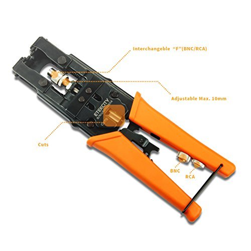
Etekcity Multifunctional Coax Compression Connector Adjustable Tool, Wire Cutter, for RG58 RG59 RG6 F BNC RCA http://ift.tt/2C3BGZy
0 notes
Video
youtube
Buy it on Amazon - http://ift.tt/2DlggnC - Coax Cable Crimper Kit Tool for RG6 RG59/62 and RG58 Coaxial Compression Tool Fitting with Gaobige 10 PCS F Compression connectors - Grey Review -- Click the link to buy now or to read the 4 4 & 5 Star Reviews.Subscribe to our Channel: https://www.youtube.com/channel/UC34yudB5hvLGFwHHPVXKwtg?sub_confirmation=1 Like us on Facebook for videos, pictures, coupons, prizes and more - http://ift.tt/2wCDdi2 Coax Cable Crimper Kit Tool for RG6 RG59/62 and RG58 Coaxial Compression Tool Fitting with Gaobige 10 PCS F Compression connectors - Grey Review Great tools. The crimper and wire stripper are really nice quality. I have put allot of cable tv wires together. This set is well worth the money. The compression type ends are the only way to go! ... Reviewer : Cmooney These are all that I need to upgrade our cable installation with some new equipment. Both the compression tool and the cable stripper along with cable ends are included. Its a complete solution of excellent quality. ... Reviewer : speakez99 Click http://ift.tt/2DlggnC to buy now on Amazon or to read more reviews. FULLY ADJUSTABLE AND REPLACEABLE BLADES CAN STRIP CABLE PERFECTLY: Work with RG-59, RG-59 Quad, RG-6, RG-6 Quad, and RG-58, 3V, 2V, 4C, 5C. Equipped with hexagonal tools can adjust the depth of the v-shaped incision, 3 to 7 Clockwise circle, one-time peeling, keep inner core. SOLIDLY BUILT CRIMPING TOOL CAN PRECISE EXTRUSION THE F CONNECTORS: Work with rg-6, rg-59, rg-59, bnc, rca etc. compatible for most brands of compression connectors. e.g. ppc, digicon, gilbert, holland, thomas and betts snap and seal, ultrease, stirling, lock and seal, etc. PREMIUM QUALITY F CONNECTORS PREFECT FOR RG6 COAXIAL CABLE: It provides a professional, secure, waterproof connection for RG6 coaxial cable. Anti-corrosion nickel-plated. For indoor/outdoor use for a tight weather sealed connection. LIGHTWEIGHT AND EASY TO CARRY FOR INDOOR/OUTDOOR USE: Very convenient to install a satellite tv dish /cctv , move cable tv and cable modem, or wire up the cables for your new house. Coax Cable Crimper Coaxial Compression Tool RG6 Fitting with Gaobige 10 PCS F Compression connectors - Yellow Is coax cable compression crimper is perfect. It's simple to use and you can make coax cables any size you want and crimp the ends on professionally. The blade is adjustable so you will be able to cut insulation of any thickness. Will do rg59 or RG6 or rg7 or rg11 cables. Works with almost all of the compression connectors out there. The end result is waterproof and super ... Reviewer : Richard Klingler Click http://ift.tt/2DlggnC to buy now on Amazon or to read more reviews. ***Let Us Know What You Think… Comment Below!!*** Watch my other review Videos – https://www.youtube.com/channel/UC34yudB5hvLGFwHHPVXKwtg See other products on http://ift.tt/2xhK4Ru Subscribe to our Channel: https://www.youtube.com/channel/UC34yudB5hvLGFwHHPVXKwtg?sub_confirmation=1 Like us on Facebook for videos, pictures, coupons, prizes and more - http://ift.tt/2wCDdi2 #Gaobige, #Coax Cable Crimper Kit Tool for RG6 RG59/62 and RG58 Coaxial Compression Tool Fitting with Gaobige 10 PCS F Compression connectors - Grey This is a review video for : B073TWL5G4 Manufacture : Gaobige Thanks for watching! http://ift.tt/2xhK4Ru Related Videos in Channel
0 notes
Text
Review: Teradek Serv Pro and VUER
Teradek’s Serv Pro is a $1799 camera-top wireless transmitter, sending H.264 video and audio to as many as ten iPhones, iPads, or iPod touches. VUER is the free app that receives the Serv Pro’s transmissions. The two combined form a wireless monitoring system for any production that needs to show a feed to multiple people and doesn’t want the bother of running cables.
Serv Pro on a GH4
VUER displaying Serv Pro’s feed
Serv Pro fills a unique niche. There are uncompressed camera-top transmitters like the Paralinx systems and Teradek’s own Bolt series; these are real-time links with zero latency—or close enough as makes no difference—sending signals from cameras to one or more receivers, which then feed SDI or HDMI to monitors. These systems use dedicated high-bandwidth radio links and require matched transmitter/receiver pairs. Uncompressed transmitters are the industry standard for wireless monitoring, as the signal is detailed enough and timely enough for remote operating, focus-pulling, and engineering.
There are compressed systems, like Teradek’s Cube and VidiU, which send long-GOP video over Wi-Fi, Wired Ethernet, and/or 3G+ mobile channels. These systems are designed to be used for live streaming, but can also send pictures and sound to apps on mobile devices like iPads and iPhones, which act as combined receivers and displays.
As iPhones and iPads have become commonplace, Cubes and their ilk have been pressed into service as non-realtime “secondary” transmitters for those who can live with the slight delay incurred by long-GOP H.264 compression. It’s not uncommon on larger productions for a Bolt or Paralinx system to send a feed to video village, where a Cube transmitter re-encodes the feed for distribution to Various Important People with iDevices. Cubes also work as primary wireless transmitters on lower-budget (or just lower-footprint) productions, offering comparatively low-cost remote monitoring for cameras on gimbals, Steadicams, shoulder rigs, jibs, and car mounts.
It’s a handy thing to be able to do, but as iPhones and iPads proliferate on-set, Cubes show their limits: they’re fine feeding two or three iOS devices, but have increasing difficulty with more, lagging intolerably when trying to handle more than four. They can also be daunting to set up due to their more complex configuration menus—a necessity given their wide-ranging capabilities.
Thus the Serv Pro: a dedicated iOS streamer. Teradek says a Serv Pro will feed ten iOS devices as easily as one. That’s all it does. It’s very much a one-trick pony, but if that’s the sort of trick you need to pull off, this is the pony to do it.
Serv Pro Hardware
The Serv Pro is wrapped in a blue anodized aluminum box, 4.75″ x 3″ x 1.1″ (121 x 76 x 28mm), with diagonally-grooved heat dissipation fins. With its two Wi-Fi antennas attached it tips the scales at 14 oz (398g).
Serv Pro with iPhone 6 running VUER
The left side (assuming you mount the device with the control panel on the left) has four status LEDs and a dot-matrix display, plus two stubby rubber joystick-buttons for menu navigation.
There’s a 1/4×20 mounting socket on the back.
The right side has an HD-SDI input BNC, a full-size HDMI input, a 10/100/1000baseT wired Ethernet port, a two-pin Lemo power input with a power switch, and a 3.5mm minijack for line/mic audio input (SDI and HDMI allow embedded audio, too).
The front has two terminals for the supplied Wi-Fi antennas.
The underside has another 1/4×20 mounting point.
The Serv Pro comes with two tiltable antennas; a multivoltage AC adapter, including plugs for just about anywhere in the world; a 1/4×20 shoe mount adapter; short Ethernet and HDMI cables; a very slick coiled SDI cable with right-angle BNCs; and four adorably tiny rubber stick-on feet in case you wish to use Serv Pro flat on a table.
There’s also a single sheet of instructions. Because that’s all you need.
Operation
Mount the Serv Pro where it’s needed. Connect your input. Supply power. Turn it on. You’re done. Seriously, you can be up and running that easily. Serv Pro comes out of the box set up to establish its own wireless network (Access Point mode, in Teradek terms) and start streaming as soon as it’s initialized.
From power on to pictures received in VUER takes just over two minutes. Unlike 2nd-generation Cubes, Serv Pro does not have an internal bridge battery, so you’ll be off-air for two minutes at every power change. The DC input on the Serv Pro accepts 6–28 volts and both Teradek and third parties offer a variety of power input cables and battery plates; a D-tap cable is perhaps the most common cable used.
Serv Pro dissipates about 8 watts, and the casing gets quite warm in use, though not uncomfortably so. If you’re going to put it flat on a table, use those rubber feet, so air can circulate beneath the box.
By default, the Serv Pro auto-selects a channel on either 2.4GHz or 5GHz Wi-Fi bands and creates an open network. Anyone with VUER loaded on an iOS device can connect to that network and start viewing the feed.
If you prefer, you can limit channel selection to either the 2.4 or 5GHz bands, choose the channel directly, enable Wi-Fi password protection and/or stream encryption (encryption requires the just-released version 2.1 firmware), and/or switch the Serv Pro into “infrastructure mode” to connect through a different Wi-Fi network instead of creating its own. All this can be done using the side panel’s display and joysticks, or—more easily—through the embedded webpage, available over both the wired and wireless interfaces.
Why would an iOS streaming device offer a wired interface? It’s handy for firmware updates, and for Camera Link: Serv Pro can act as a wireless access point for a variety of cameras with Ethernet ports, so you can connect to their embedded webservers from your iPhone or iPad.
VUER
VUER is Teradek’s free app for receiving Serv Pro feeds. It runs on any iDevice with an A7 or better processor (iPhone 5S or later, iPad 5th generation or later, iPad mini 2 or later, iPod touch 6G) running iOS 9 or later. It can display one, two, or four images simultaneously from up to four Serv Pros and/or 3rd-generation Cubes, depending on the iDevice—it only allowed three simultaneous feeds on my iPad Air.
VUER’s screen on iPhone with no inputs configured
VUER sees one Serv Pro on the network
You can use the same input for all four channels
VUER gives a snapshot tutorial on important controls
VUER offers a wide variety of settings and adjustments. You can pinch-zoom the image. You can apply peaking (“analog style”, in white), focus assist (“digital style” in several colors), false color, anamorphic desqueeze, and ‘scopes: waveform monitor, vectorscope, and histogram. You can also load LUTs or CDLs, and display a CDL editor onscreen:
VUER’s CDL editor, on iPad
There’s even a link to Pomfort LiveGrade: VUER can control LiveGrade, or vice versa.
You have control over the Serv Pro’s resolution and bitrate, and VUER’s decoding delay. Lowering resolution and/or bitrate may allow better performance on congested networks or at longer distances. Adding some delay—up to 1 second—may help when signal quality is poor; there’s time for retries when packets get dropped. Teradek’s TeraView app helpfully labels its version of this slider as “Lower Delay” vs. “Smoother Video”.
VUER gives you direct control over the iDevice’s screen brightness and audio volume, so you don’t have to fumble with buttons or the iOS control panel. Combinations of inputs and screen layouts can be saved as workspaces, so you can bounce between different setups without manually reconfiguring your inputs and displays. There’s a frame grab manager, so you can save grabbed frames to the Camera Roll or load them from the Camera Roll; frame grabs can be supered and crossfaded to/from using a Frame Compare tool.
Teradek has a hands-on walkthrough video, and here are a few screenshots:
VUER’s Distort settings, set for a 2.0x desqueeze
Comprehensive marker and mask settings
The result: 2.0x anamorphic with 2.39:1 framing
Quad-split display with false color, WFM, focus assist
Three clients, no problems
Performance
Teradek claims that Serv Pro supports up to ten iOS clients with a mere two-frame delay at distances of up to 300 feet. I set out to test this as best I could.
To look at delay, I compared Serv Pro (connected to an iPhone SE) against a Video Devices PIX-E5 and a Convergent Design Odyssey 7Q+, all fed from the same HDMI output on a GH4. I set up a “shoot ‘em all” scene as described here, capturing the live image off MovieSlate’s timecode display alongside the output of the device under test. I shot a few seconds of each scene, and looked at the lag in the readout of the device being tested as compared to the source timecode slate. I did the tests with the slate and the taking camera set to 60p, and then at 24p (60p is a bit of a cheat, as the Serv Pro’s transmitted image tops out at 1080/30p, but at least I’d get a high-temporal-resolution result). Note that VUER defaults to a 200ms delay; I set its delay to 0ms to get the lowest possible latency.
At 60p, the image displayed by the Serv Pro was usually 5 60p frames behind those of the Pix-E and Odyssey. I say “usually” because once in a while the delay was a frame better or a frame worse; H.264 over Wi-Fi doesn’t have a guaranteed latency. 60p is 2.5x faster than 24p; 5 ÷ 2.5 = 2 frames of delay at 24p.
And sure enough, at 24p, the Serv Pro was usually 2 frames behind the PIX-E or Odyssey. Those hardwired devices lagged the live image by 5 frames (the GH4’s HDMI delivery has its own not insubstantial delay), while the Teradek’s overall delay was usually 7 frames.
Furthermore, this same latency held with six clients:
The slate says “7 clients” because I expected an iPhone 4S to be in the mix, but it fell beneath VUER’s minimum requirements and I forgot to change the slate.
I had everything from an iPhone 5S to a pair of iPad Pros, and performance was comparable across all of them.
Adding an image effect like False Color or Focus Assist occasionally caused an additional frame or two of delay:
This only occurred perhaps a third of the time (I cherry-picked that frame grab), and it’s to be expected: adding a processing step adds a delay even if it’s usually under a frame.
Overall I’d rate this as excellent performance for a compressed transmitter using an iPhone as a a receiver/monitor. On a camera with a lower-latency output (yes, I know, like a real camera such as the F55, where the SDI output is only two frames behind reality), it may even be fast enough for operating or focus pulling in certain circumstances.
Mind you, this behavior was measured under near-ideal conditions: all receivers within arm’s length of the transmitter, in a reasonably uncrowded Wi-Fi environment.
Once I started walking away with my iPhones, I saw a gradual degradation in performance—both in overall latency, and in the smooth and continuous delivery of frames—depending on distance and the amount of stuff between transmitter and receiver. Putting as many interior walls between me and the Serv Pro as possible, I’d get hiccups and even the occasional total signal loss in under 50 feet (15 meters). With the rig outdoors, I was able to walk about 360 feet (110 meters) down the road before signal was lost, though I started seeing increased latency, hiccups, and dropped frames starting around 250 feet or so. At the 360 foot point, a delivery delay of over 4 seconds (as handily reported by VUER’s video statistics overlay) wasn’t unusual… but consider that I was 20% beyond the Serv Pro’s specified range.
It’s Wi-Fi, after all: it’s an unlicensed, shared chunk of spectrum, and performance is not guaranteed. If the built-in access point in the Serv Pro doesn’t have the punch you need, consider an industrial-strength access point with high-gain antennas, advanced beam-forming, and sophisticated interference rejection. Teradek makes their own, the production-friendly Link. Commercial units by the likes of Ubiquiti and Ruckus are how the pros provide access in trying situations; Teradek uses Ruckus APs at NAB and IBC (or at least they did before they built the Link), two shows with notoriously crowded Wi-Fi airwaves.
I can personally attest to the fact that at Teradek’s NAB booth, all the Cube and Serv Pro Wi-Fi feeds were smooth and problem-free. 100 feet away in the DSC Labs booth, I was trying to run a Cube in both standalone and infrastructure mode, using a weedy little consumer-grade access point. Half the time I couldn’t even connect an iPad to the Cube, and when I could, frame drops and scrambled video were common. The access point makes all the difference.
As far as VUER goes, it’s a very complete monitoring system. I found it useful to set up a quad-split, typically with a raw image, an image with focus assist, one with false color, and the fourth with a full-size, RGB overlay WFM. Double-tapping any quadrant makes that image full-screen; double-tap again to return to the quad split. Fast and easy.
I only have a couple of quibbles:
The WFM and Histogram only show studio-swing range (0%–100%), so anything below black or between 100% and 109% will be lost. The WFM’s scale has divisions every 16.7%, unlike any other WFM around; the histogram is divided every 8.3%, likewise (in this way VUER is much like FCPX: the designers gave us scales because scales were on the feature list, without ever bothering to figure out what the scales should actually be. Not that I have an opinion or anything, mind you).
WFM: six steps from 0% to 100%?
The top-and-bottom control bars are outside the 16×9 picture area on a 1.5:1 iPad, but they overlay and obscure picture (and info boxes, and ‘scopes) on a 16×9 iPhone. Yes, the control bars are easily hidden, but as their background is opaque, it’s not always clear at a glance that they’re hiding anything beneath them.
The menu bar overlays the data panel…
…and the picture too, as it turns out.
That’s all I can find to complain about, sorry. Teradek have done a fine job on the software.
VUER, like any such app, tends to be relatively power hungry: it’s flogging the hardware mercilessly to receive, decompress, process, and display images as quickly as possible. In my testing I typically saw a drop in battery level of 10% in half an hour whether I was using an iPhone or iPad: a fully charged iDevice will be drained in around five hours.
Conclusion
At $1799, Serv Pro isn’t cheap, but it’s pretty much the only game in town if you need to feed a multitude of iOS devices from a single transmitter.
Yes, a 2nd-generation Cube can be had for slightly less money (or rather less on the used market), but those cubes are HDMI-only or SDI-only, require considerably more configuration, won’t handle more than four clients, and don’t (officially or reliably) display in VUER. A Cube 655 costs $200 more and tops out at six clients, and it’s still a Swiss-Army-knife transmitter, with a plethora of possibly confusing configuration options.
At NAB 2017, Teradek also mentioned a Serv (not Pro), with HDMI only, a four-client limit, and a price around $700. That’ll be a good alternative if and when it ships (Teradek tells me it’s still on the roadmap, awaiting a new encoding platform), as long as you don’t need SDI and don’t need more than four clients. And, of course, it won’t help you today.
Here’s the beauty of the Serv Pro:
Plug it in.
Turn it on.
Two minutes later: pictures!
It’’s hard to beat that.
If $1799 is a bit too spendy, consider renting one when you need it. They’re new, so not yet widely available, but a quick snuffling ‘round shows that Chater Camera in Berkeley CA has one for $150/day. Your local rental house might offer it, too, especially if you let ‘em know you need such a thing.
If you’ve come this far and are shaking your head at the things fools waste their money on, then Serv Pro isn’t for you. But if you need to feed pix and sound to Various Important People who can’t be tied down with wired monitors, you may very well look at it and say, “where’ve you been all my life?”
It’s a one-trick pony, but it does that trick very well indeed. It just works. Isn’t that what you want on a shoot?
Pros
Drop-dead simple to use on default settings; easy enough to change those defaults when necessary.
1080p feeds to as many as 10 iOS devices with minimal delay.
SDI and HDMI inputs, with embedded or separate audio.
Full-featured VUER app with full look management, frame guides, engineering ‘scopes, false color, peaking, multiple feeds, multiple views, and more.
Cons
$1799, not cheap! But if you need it, you need it.
Two minutes from power on to picture, and no internal bridge battery.
Cautions
Signal stability and latency are entirely at the mercy of local Wi-Fi conditions. If you need more range or robustness than Serv Pro’s default setup provides, it’s up to you to change the default settings, find uncongested channels, and/or configure an enterprise-class Wi-Fi access point to create your own Information Superhighway.
Serv Pro serves video to iOS devices only. Android is not supported and there are no plans to do so in the future.
VUER will drain an iDevice dry in about five hours, so tell your Director and AD and the other Important People to turn their devices off between setups, and not to just put ‘em down on a chair and wander away, leaving ‘em playing, or they won’t have any pretty pictures to look at after lunch. I know, it won’t work: people are forgetful and easily distracted, and it’ll be your fault their iPhones have run down and their iPads have died. No matter what happens, it’s always your fault. But that’s why you get paid the big, big money, right?
Because the Internet, and cats.
Disclosure: Teradek sent me a Serv Pro for review, and paid shipping both ways. I own two 2nd-generation Cubes, purchased used, and I use Teradek’s SDK to support Cubes, Clips, and VidiUs in my FieldMonitor app. Chater Camera was one of my two neighborhood rental shops when I lived in Silicon Valley, so their website was one of the ones I looked at seeking rental Serv Pros. Those aside, there’s no material connection between me and Teradek or Chater, and neither one has offered any payments, considerations, emoluments, blandishments, free weekends at Pismo beach, or outright bribes for a favorable mention.
The post Review: Teradek Serv Pro and VUER appeared first on ProVideo Coalition.
First Found At: Review: Teradek Serv Pro and VUER
0 notes
Text
Network Cabling and Installation
New Post has been published on https://myupdatesystems.com/2017/04/14/network-cabling-and-installation/
Network Cabling and Installation
Have you ever wondered what it is that connects computers and networks to one another? Network cable in conjunction with the associated hardware (network switches, hubs, demarcation equipment) is responsible for computers being able to connect and transfer data across intranets (internal network) and the internet. Network cabling today is used for many other purposes besides computer networking. It can be used to carry video for security camera systems as well as the video for cable TV and AV (Audio/Visual) applications. Network cabling is also used as control cable in Building Maintenance Systems and Access Control Systems. There are several different types of cables that are used for this purpose, including unshielded twisted pair, shielded twisted pair, fiber optic and coaxial. In some cases, only one type of cable is used in a network, while in other cases, many different types are used. Wireless systems are becoming more and more popular but always remember you still need network cabling for the wireless system. There is still two things that make network cabling better than a wireless network: it is much more secure and reliable.
Understanding Cable Type
Before you can really understand how cable networking works, you need to know about the various cables and how they work. Each cable is different, and the type of cable used for a particular network needs to be related to the size, topology, and protocol of the network. Here is a rundown of the cables that are most commonly used for network cabling:
Unshielded/Shielded Twisted Pair – This is the type of cable that is used for many Ethernet networks. There are four sets of pairs of wires inside the cable. There is a thick plastic separator that keeps each pair isolated through the run of cable. Each pair of wires is twisted so there will be no interference from other devices that are on the same network. The pairs are also twisted at different intervals so they will not cause interference between themselves. In an application where there is a lot of Electromagnetic Interference (EMI), such as a mechanical space, you may choose to use shielded twisted pair, which has an outer shielding that adds extra protection from EMI. Category 5e, 6, 6A and 7 are the general choices today. Twisted pair cable is limited to 295′ on a horizontal run. Twisted pair cable is used for many applications. Standard station cabling for computers and VOIP phones, wireless access points, network cameras, access control and building maintenance systems are just a few. This is one of the most reliable types of cables, and when used, network failures are less common than when other cables are used.
Fiber Optic – Fiber optic cable is primarily used as backbone cable although it is being used more and more as station cable (think FIOS). By backbone cable I mean it connects Telecommunication Rooms within a space to each other. Fiber optic cable has huge broadband capacities which allow it to carry large amounts of information as super fast speeds. Fiber cables can cover great distances(hundreds of meters) as opposed to copper cable. Because these cables must work so hard and the information travels such distances, there are many layers of protective coating on fiber optic cables. Fiber cables transmit light as opposed to electrical current. Fiber optic cable requires much less power than high-speed copper does. Fiber optic cable is a great choice for high-speed reliable communications.
Coaxial Cable – Coaxial cable usually falls under the scope of work of the network cabling installation contractor. Coax will be used for the cable television locations within the space you are cabling. The service provider will drop off the outdoor cable at the point of entry. The contractor will run an extension (usually RG-11) to the local telecom closet within the space. The individual station runs(RG-6) will terminate on a splitter to connect to the service cable. The center of this type of cable has a copper conductor and a plastic coating that acts as an insulator between the conductor and the metal shield. This cable is covered with the coating, which can vary in thickness. The thicker the coating, the less flexible it is going to be. There are a few types of terminations for coax. Compression, crimp and twist on are the three types of terminations. The best method is compression as long as they are performed correctly. Crimp terminations are also reliable and require the right tool for the particular connector you are using. I would not recommend twist on as they are not reliable and prone to problems. A few types of coax connectors are F connectors, BNC connectors, and RCA connector.
Network Cabling Components
Patch panel – This is the panel where all of the station cables terminate within the Telecommunications Room. They are usually mounted on a wall mount or floor mount telecommunications rack. Typically there are 24, 48 or 72 ports on a patch panel. There are a few different styles such as angled or straight. Panels also have the option of having the 110 type pins attached to the back of the panel or you can terminate jacks and snap them into the empty panel.
Data Jack – This is the connector where each individual cable is terminated out at the station side. The jacks are snapped into a faceplate ranging from 1 to 8 ports typically. Data jacks can be terminated in a 568A or 568B pinout. Check with the customer or designer for the correct pinout.
RJ 45 Connector – The RJ-45 connector is installed on the end of a network cable. They are 8 pin connectors. The most common place to find the RJ 45 is on a cable terminating at a wireless access point. The RJ 45 is a male connector and would plug into the port on the WAP.
Wireless Access Points – These are devices that transmit network access wirelessly. Typically they are mounted on the ceiling or wall. A wireless survey would need to be performed to maximize the correct placement of WAP’s. Contrary to popular belief wireless devices STILL need to be fed with network cabling.
Cable Supports – (Commonly called J-Hooks) Cable supports are mounted in the ceiling as a support structure for your cable bundles. Main path cable supports should be mounted to the concrete deck ceiling within the space. You are no longer permitted to hang j-hooks from ceiling supports, electrical or plumbing pipe or any other system infrastructure.
Wire Managers – Wire managers are installed between patch panels and switches to manage patch cables. They serve a very important purpose as they keep law and order in a Telecommunications Room. Nothing irks me more than finishing a brand new beautiful install and having the IT group come in and not use the wire managers. It ruins the aesthetics of the job. In addition, it sets a bad precedence from the birth of the Telecommunications Room that others are sure to follow.
Firestop Sleeves – Firestop sleeves are a vital part of any network cabling installation these days. Gone are the days of just banging holes into sheetrock and passing cables through. When you penetrate any firewall on a job you must install a firestop sleeve. There are specific products made for this. EZ Path and Hilti both make excellent versions in varying sizes. You can install a sleeve of EMT pipe through a wall also as long as you use firestop putty or firestop silicone to seal off all openings. This can save lives and minimize damage in the event of a fire.
Cable Labels – All cables and termination points should have a unique label. This makes installation, maintenance and troubleshooting much simpler. For a professional, all labels should be computer generated. Handwritten labels are just not acceptable today.
Network Cabling Installation
Network cabling installation drawings should be designed by a BICSI certified RCDD (Registered Communication Distribution Designer). There are a few things that need to be considered.
The type of cabling solution to be implemented – The cabling vendor or customer will need to select a solutions manufacturer. Siemon, Leviton, Ortronics and Panduit are some of the more common choices. The type of cabling solution will need to be discussed. Cat 5e, Cat 6, Cat 6A or Cat 7 are the copper types of network cables that can be offered. The style of the racks, data jacks, faceplates, patch panels and wire managers will also need to be discussed and chosen. Make sure this is done early as lead times can be long for certain manufacturers and styles.
The location of the network equipment and racks – The room where they are housed is commonly referred to as MDF (Main Distribution Frame) Data Room, Telco Room or Telecommunications Room. All cables run need to be within 100 meters. If cable runs are going to be over 100 meters you will need to add a second Telecommunications Room. This is also called an IDF(intermediate Distribution Frame). The IDF will often need to be connected to the MDF via fiber optic backbone cabling. The MDF will house the service provider feed from the street, which will feed the network. Typically you will also find security equipment and access control equipment here. It is a better design to have all the low voltage systems housed in one location. Measure all equipment and racks that will be required based on cabling quantities. Include access control, security, electrical panels and air conditioning units. The room needs to be large enough to accommodate all equipment.
The pathways of the cable trunks above the ceilings – Cable paths need to steer clear of electrical light fixtures or other sources of EMI (Electro Magnetic Interference). Keep cable paths inaccessible areas of the ceiling for future cable runs and ease of maintenance. All paths should be run above hallways or corridors and cables enter individual rooms on sweeping 90-degree turns. Install a firestop sleeve or putty for all penetrations of a firewall. Be careful when pulling cables so as not to bend them beyond their bend radius. This will cause a failure when testing. DO NOT tie cables to ceiling hangers or sprinkler pipes. They need to be tied at least every 5′ on horizontal runs, and even more on vertical runs. J-hook supports should be anchored to the concrete deck above. Use velcro wraps every 5′ or so when finished running cable to give your cable bundles a great looking finish.
Terminating Network Cabling – When terminating cable makes sure to check the floor-plan numbering to each cable label to make sure the cables are in the correct spot. If something is not matching leave that cable on the side to be “toned out” later on. Use a cable stripping & cutting tool to get a uniform cut on the cable jacket and to be sure you won’t nick the copper conductors inside. Always keep each pair twisted as tight as possible right up to the pins where you terminate the cable. This will ensure you won’t get a NEXT or Return Loss failure. Before you start any terminations inquire whether the pinout will be 568A or 568B. This will determine which order the conductors are terminated in and are very important before you start. All cables should be dressed nicely and uniform. The project manager should make a termination chart of the patch panels for the technician that will perform the terminations. This will show the back of the patch panels and where each cable gets terminated with its label number.
Testing your network cabling – There are a number of cabling testers out on the market. The tester we prefer to use is the Fluke DTX-1800 Cable Analyzer. This is an amazing tool. It will give you a detailed report of each cable that is tested. It tests for wiretap, insertion loss, NEXT, PSNEXT, ACR-N, Insertion Loss and many others. The best part about these new age testers is their troubleshooting skills. The Fluke will tell you where a cable is damaged and which particular conductor is damaged. If you terminated a pair out of sequence the tester will tell you which pair and on what end the error was made. The Fluke does everything but fixes it for you! Most clients want to see verified test results. The new testers will provide cleaned up PDF files of the test results. These can be emailed directly to the client.
0 notes
Text
Network Cabling and Installation
New Post has been published on https://netmaddy.com/network-cabling-and-installation/
Network Cabling and Installation
Have you ever wondered what it is that connects computers and networks to one another? Network cable in conjunction with the associated hardware (network switches, hubs, demarcation equipment) is responsible for computers being able to connect and transfer data across intranets (internal network) and the internet. Network cabling today is used for many other purposes besides computer networking. It can be used to carry video for security camera systems as well as video for cable TV and AV (Audio/Visual) applications. Network cabling is also used as control cable in Building Maintenance Systems and Access Control Systems. There are several different types of cables that are used for this purpose, including unshielded twisted pair, shielded twisted pair, fiber optic and coaxial. In some cases, only one type of cable is used in a network, while in other cases, many different types are used. Wireless systems are becoming more and more popular but always remember you still need network cabling for the wireless system. There is still two things that make network cabling better than a wireless network: it is much more secure and reliable.
Understanding Cable Type
Before you can really understand how cable networking works, you need to know about the various cables and how they work. Each cable is different, and the type of cable used for a particular network needs to be related to the size, topology and protocol of the network. Here is a rundown of the cables that are most commonly used for network cabling:
Unshielded/Shielded Twisted Pair – This is the type of cable that is used for many Ethernet networks. There are four sets of pairs of wires inside the cable. There is a thick plastic separator that keeps each pair isolated through the run of cable. Each pair of wires are twisted so there will be no interference from other devices that are on the same network. The pairs are also twisted at different intervals so they will not cause interference between themselves. In an application where there is a lot of Electromagnetic Interference (EMI), such as a mechanical space, you may choose to use shielded twisted pair, which has an outer shielding that adds extra protection from EMI. Category 5e, 6, 6A and 7 are the general choices today. Twisted pair cable is limited to 295′ on a horizontal run. Twisted pair cable is used for many applications. Standard station cabling for computers and VOIP phones, wireless access points, network cameras, access control and building maintenance systems are just a few. This is one of the most reliable types of cables, and when used, network failures are less common than when other cables are used.
Fiber Optic – Fiber optic cable is primarily used as backbone cable although it is being used more and more as station cable (think FIOS). By backbone cable I mean it connects Telecommunication Rooms within a space to each other. Fiber optic cable has huge broadband capacities which allow it to carry large amounts of information as super fast speeds. Fiber cables can cover great distances(hundreds of meters) as opposed to copper cable. Because these cables must work so hard and the information travels such distances, there are many layers of protective coating on fiber optic cables. Fiber cables transmit light as opposed to electrical current. Fiber optic cable requires much less power than high speed copper does. Fiber optic cable is a great choice for high speed reliable communications.
Coaxial Cable – Coaxial cable usually falls under the scope of work of the network cabling installation contractor. Coax will be used for the cable television locations within the space you are cabling. The service provider will drop off the outdoor cable at the point of entry. The contractor will run an extension (usually RG-11) to the local telecom closet within the space. The individual station runs(RG-6) will terminate on a splitter to connect to the service cable. The center of this type of cable has a copper conductor and a plastic coating that acts as an insulator between the conductor and the metal shield. This cable is covered with coating, which can vary in thickness. The thicker the coating, the less flexible it is going to be. There are a few types of terminations for coax. Compression, crimp and twist on are the three types of terminations. The best method is compression as long as they are performed correctly. Crimp terminations are also reliable and require the right tool for the particular connector you are using. I would not recommend twist on as they are not reliable and prone to problems. A few types of coax connectors are F connectors, BNC connectors and RCA connector.
Network Cabling Components
Patch panel – This is the panel where all of the station cables terminate within the Telecommunications Room. They are usually mounted on a wall mount or floor mount telecommunications rack. Typically there are 24, 48 or 72 ports on a patch panel. There are a few different styles such as angled or straight. Panels also have the option of having the 110 type pins attached to the back of the panel or you can terminate jacks and snap them into the empty panel.
Data Jack – This is the connector where each individual cable is terminated out at the station side. The jacks are snapped into a faceplate ranging from 1 to 8 ports typically. Data jacks can be terminated in a 568A or 568B pinout. Check with the customer or designer for the correct pinout.
RJ 45 Connector – The RJ-45 connector is installed on the end of a network cable. They are 8 pin connectors. The most common place to find the RJ 45 is on a cable terminating at a wireless access point. The RJ 45 is a male connector and would plug into the port on the WAP.
Wireless Access Points – These are devices that transmit network access wirelessly. Typically they are mounted on the ceiling or wall. A wireless survey would need to be performed to maximize the correct placement of WAP’s. Contrary to popular belief wireless devices STILL need to be fed with network cabling.
Cable Supports – (Commonly called J-Hooks) Cable supports are mounted in the ceiling as a support structure for your cable bundles. Main path cable supports should be mounted to the concrete deck ceiling within the space. You are no longer permitted to hang j-hooks from ceiling supports, electrical or plumbing pipe or any other system infrastructure.
Wire Managers – Wire managers are installed between patch panels and switches to manage patch cables. They serve a very important purpose as they keep law and order in a Telecommunications Room. Nothing irks me more than finishing a brand new beautiful install and having the IT group come in and not use the wire managers. It ruins the aesthetics of the job. In addition it sets a bad precedence from the birth of the Telecommunications Room that others are sure to follow.
Firestop Sleeves – Firestop sleeves are a vital part of any network cabling installation these days. Gone are the days of just banging holes into sheetrock and passing cables through. When you penetrate any firewall on a job you must install a firestop sleeve. There are specific products made for this. EZ Path and Hilti both make excellent versions in varying sizes. You can install a sleeve of EMT pipe through a wall also as long as you use firestop putty or firestop silicone to seal off all openings. This can save lives and minimize damage in the event of a fire.
Cable Labels – All cables and termination points should have a unique label. This makes installation, maintenance and troubleshooting much simpler. For a professional all labels should be computer generated. Hand written labels are just not acceptable today.
Network Cabling Installation
Network cabling installation drawings should be designed by a BICSI certified RCDD (Registered Communication Distribution Designer). There are a few things that need to be considered.
The type of cabling solution to be implemented – The cabling vendor or customer will need to select a solutions manufacturer. Siemon, Leviton, Ortronics and Panduit are some of the more common choices. The type of cabling solution will need to be discussed. Cat 5e, Cat 6, Cat 6A or Cat 7 are the copper types of network cables that can be offered. The style of the racks, data jacks, faceplates, patch panels and wire managers will also need to be discussed and chosen. Make sure this is done early as lead times can be long for certain manufactures and styles.
The location of the network equipment and racks – The room where they are housed is commonly referred to as MDF (Main Distribution Frame) Data Room, Telco Room or Telecommunications Room. All cables runs need to be within 100 meters. If cable runs are going to be over 100 meters you will need to add a second Telecommunications Room. This is also called an IDF(intermediate Distribution Frame). The IDF will often need to be connected to the MDF via fiber optic backbone cabling. The MDF will house the service provider feed from the street, which will feed the network. Typically you will also find security equipment and access control equipment here. It is a better design to have all the low voltage systems housed in one location. Measure all equipment and racks that will be required based on cabling quantities. Include access control, security, electrical panels and air conditioning units. The room needs to be large enough to accommodate all equipment.
The pathways of the cable trunks above the ceilings – Cable paths need to steer clear of electrical light fixtures or other sources of EMI (Electro Magnetic Interference). Keep cable paths in accessible areas of the ceiling for future cable runs and ease of maintenance. All paths should be run above hallways or corridors and cables enter individual rooms on sweeping 90 degree turns. Install a firestop sleeve or putty for all penetrations of a fire wall. Be careful when pulling cables so as not to bend them beyond their bend radius. This will cause a failure when testing. DO NOT tie cables to ceiling hangers or sprinkler pipes. They need to be tied at least every 5′ on horizontal runs, and even more on vertical runs. J-hook supports should be anchored to the concrete deck above. Use velcro wraps every 5′ or so when finished running cable to give your cable bundles a great looking finish.
Terminating Network Cabling – When terminating cable make sure to check the floor-plan numbering to each cable label to make sure the cables are in the correct spot. If something is not matching leave that cable on the side to be “toned out” later on. Use a cable stripping & cutting tool to get a uniform cut on the cable jacket and to be sure you won’t nick the copper conductors inside. Always keep each pair twisted as tight as possible right up to the pins where you terminate the cable. This will ensure you won’t get a NEXT or Return Loss failure. Before you start any terminations inquire weather the pinout will be 568A or 568B. This will determine which order the conductors are terminated in and is very important before you start. All cables should be dressed nicely and uniform. The project manager should make a termination chart of the patch panels for the technician that will perform the terminations. This will show the back of the patch panels and where each cable gets terminated with it’s label number.
Testing your network cabling – There are a number of cabling testers out on the market. The tester we prefer to use is the Fluke DTX-1800 Cable Analyzer. This is an amazing tool. It will give you a detailed report of each cable that is tested. It tests for wiremap, insertion loss, NEXT, PSNEXT, ACR-N, Insertion Loss and many others. The best part about these new age testers is their troubleshooting skills. The Fluke will tell you where a cable is damaged and which particular conductor is damaged. If you terminated a pair out of sequence the tester will tell you which pair and on what end the error was made. The Fluke does everything but fix it for you! Most clients want to see verified test results. The new testers will provide cleaned up PDF files of the test results. These can be emailed directly to the client.
0 notes