#Best Networking Transceivers
Explore tagged Tumblr posts
Visit Tumblr Blog
Explore Tumblr blogs with no restrictions, modern design and the best experience.
Last Seen Tumblr Blogs


Fun Fact
69% of Tumblr users are millennials.
Text
Global Base Transceiver Station (BTS) Market Watch 2025: Fastest Growing Segments
Global Base Transceiver Station (BTS) Market was valued at USD X.X Billion in 2024 and is projected to reach USD X.X Billion by 2032, growing at a CAGR of X.X% from 2026 to 2032. What are the potential factors contributing to the growth of the global Base Transceiver Station (BTS) market? The global BTS market is witnessing notable expansion due to increasing mobile data traffic and widespread smartphone adoption. Rapid urbanization and expanding population densities have driven the need for enhanced cellular coverage, directly boosting BTS installations. Additionally, government initiatives supporting digital infrastructure and smart city development fuel market demand. The rollout of advanced technologies such as 4G, 5G, and IoT connectivity continues to increase the need for reliable and scalable wireless communication systems, where BTS plays a key role. Rural connectivity programs and emerging economies upgrading their telecom infrastructure further promote BTS market growth. Moreover, the surge in demand for high-speed internet, video streaming, and online services creates a robust need for network capacity expansion. Technological advancements in compact, energy-efficient, and cost-effective BTS hardware are also encouraging their rapid deployment across various regions. These developments collectively push the market forward by ensuring both reach and reliability in communication networks. Get | Download Sample Copy with TOC, Graphs & List of Figures @ https://www.verifiedmarketresearch.com/download-sample/?rid=437880&utm_source=PR-News&utm_medium=205 The competitive landscape of a market explains strategies incorporated by key players of the Global Base Transceiver Station (BTS) Market. Key developments and shifts in management in recent years by players have been explained through company profiling. This helps readers to understand the trends that will accelerate the growth of the Global Base Transceiver Station (BTS) Market. It also includes investment strategies, marketing strategies, and product development plans adopted by major players of the Global Base Transceiver Station (BTS) Market. The market forecast will help readers make better investments. The report covers extensive analysis of the key market players in the market, along with their business overview, expansion plans, and strategies. The key players studied in the report include: Key Player 1 Key Player 2 Key Player 3 Key Player 4 Key Player 5 Key Player 6 Key Player 7 Key Player 8 Key Player 9 Key Player 10 Global Base Transceiver Station (BTS) Market Segmentation Global Base Transceiver Station •BTS Market Size By Technology By Component By End-User• By Geography • North America• Europe• Asia Pacific• Latin America• Middle East and Africa The comprehensive segmental analysis offered in the report digs deep into important types and application segments of the Global Base Transceiver Station (BTS) Market. It shows how leading segments are attracting growth in the Global Base Transceiver Station (BTS) Market. Moreover, it includes accurate estimations of the market share, CAGR, and market size of all segments studied in the report. Get Discount On The Purchase Of This Report @ https://www.verifiedmarketresearch.com/ask-for-discount/?rid=437880&utm_source=PR-News&utm_medium=205 The regional segmentation study is one of the best offerings of the report that explains why some regions are taking the lead in the Global Base Transceiver Station (BTS) Market while others are making a low contribution to the global market growth. Each regional market is comprehensively researched in the report with accurate predictions about its future growth potential, market share, market size, and market growth rate. Geographic Segment Covered in the Report: • North America (USA and Canada) • Europe (UK, Germany, France and the rest of Europe) • Asia Pacific (China, Japan, India, and the rest of the Asia Pacific region) • Latin America (Brazil, Mexico, and the rest of Latin America) • Middle East and Africa (GCC and rest of the Middle East and Africa)
Key questions answered in the report: • What is the growth potential of the Global Base Transceiver Station (BTS) Market? • Which product segment will take the lion's share? • Which regional market will emerge as a pioneer in the years to come? • Which application segment will experience strong growth? • What growth opportunities might arise in the Welding industry in the years to come? • What are the most significant challenges that the Global Base Transceiver Station (BTS) Market could face in the future? • Who are the leading companies on the Global Base Transceiver Station (BTS) Market? • What are the main trends that are positively impacting the growth of the market? • What growth strategies are the players considering to stay in the Global Base Transceiver Station (BTS) Market? For More Information or Query or Customization Before Buying, Visit @ https://www.verifiedmarketresearch.com/product/base-transceiver-station-bts-market/ Detailed TOC of Global Global Base Transceiver Station (BTS) Market Research Report, 2023-2030 1. Introduction of the Global Base Transceiver Station (BTS) Market Overview of the Market Scope of Report Assumptions 2. Executive Summary 3. Research Methodology of Verified Market Research Data Mining Validation Primary Interviews List of Data Sources 4. Global Base Transceiver Station (BTS) Market Outlook Overview Market Dynamics Drivers Restraints Opportunities Porters Five Force Model Value Chain Analysis 5. Global Base Transceiver Station (BTS) Market, By Product 6. Global Base Transceiver Station (BTS) Market, By Application 7. Global Base Transceiver Station (BTS) Market, By Geography North America Europe Asia Pacific Rest of the World 8. Global Base Transceiver Station (BTS) Market Competitive Landscape Overview Company Market Ranking Key Development Strategies 9. Company Profiles 10. Appendix About Us: Verified Market Research® Verified Market Research® is a leading Global Research and Consulting firm that has been providing advanced analytical research solutions, custom consulting and in-depth data analysis for 10+ years to individuals and companies alike that are looking for accurate, reliable and up to date research data and technical consulting. We offer insights into strategic and growth analyses, Data necessary to achieve corporate goals and help make critical revenue decisions. Our research studies help our clients make superior data-driven decisions, understand market forecast, capitalize on future opportunities and optimize efficiency by working as their partner to deliver accurate and valuable information. The industries we cover span over a large spectrum including Technology, Chemicals, Manufacturing, Energy, Food and Beverages, Automotive, Robotics, Packaging, Construction, Mining & Gas. Etc. We, at Verified Market Research, assist in understanding holistic market indicating factors and most current and future market trends. Our analysts, with their high expertise in data gathering and governance, utilize industry techniques to collate and examine data at all stages. They are trained to combine modern data collection techniques, superior research methodology, subject expertise and years of collective experience to produce informative and accurate research. Having serviced over 5000+ clients, we have provided reliable market research services to more than 100 Global Fortune 500 companies such as Amazon, Dell, IBM, Shell, Exxon Mobil, General Electric, Siemens, Microsoft, Sony and Hitachi. We have co-consulted with some of the world’s leading consulting firms like McKinsey & Company, Boston Consulting Group, Bain and Company for custom research and consulting projects for businesses worldwide. Contact us: Mr. Edwyne Fernandes Verified Market Research® US: +1 (650)-781-4080UK: +44 (753)-715-0008APAC: +61 (488)-85-9400US Toll-Free: +1 (800)-782-1768 Email: [email protected] Website:- https://www.verifiedmarketresearch.com/ Top Trending Reports https://www.verifiedmarketresearch.com/ko/product/germany-video-surveillance-market/
https://www.verifiedmarketresearch.com/ko/product/south-africa-oral-antidiabetic-drug-market/ https://www.verifiedmarketresearch.com/ko/product/hong-kong-capital-market/ https://www.verifiedmarketresearch.com/ko/product/hong-kong-credit-cards-market/ https://www.verifiedmarketresearch.com/ko/product/spain-light-commercial-vehicles-market/
0 notes
Text
The USB3.0 interface protects ESD applications
USB 3.0 features
Version 3.0 of the Universal Serial Bus (USB) specification offers a leap in performance over USB 2.0. Increased data rate by a factor of 10. It also extends the transmission line to 3 differential pairs (compared to 1 in the previous 2.0 generations). USB was released in version 1.0 in 1996. 1.5 Mbit/sec in low speed (LS) mode and 12 Mbit/s in full speed (FS) mode. In 2000 USB 2.0 entered the market. New high-speed (HS) modes are up to 480 Mbit/sec. It is still backward compatible with low-speed and full-speed modes.
Currently, USB 2.0 is one of the most extensive and versatile external data interfaces. It has become the default standard connector for all computer systems
Mouth.
USB 2.0 interface is also widely used in consumer electronics. Devices such as camcorders, digital cameras, digital music players, game consoles, DVD/Blu-ray players, and televisions all use USB. It is also widely used in portable devices such as smartphones and network devices such as DSL/router units.
ESD protection design considerations
For the entire USB 3.0 link, the following design considerations should be noted:
The following are mandatory.
• Non-differential coupling lines must be minimized. They have an important effect on the eye diagram.
• 90 ohm differential line width and line spacing: The coupled PCB channel should not be too narrow to avoid additional losses and be strong enough when manufacturing. The line width between the differential channels of 0.007" (0.178mm) and the line spacing of 0.007" (0.178mm) are the best choices at production time.
• The same delay (line length) between the positive and negative lines (including USB 3.0 cables) of differentially coupled connections (reducing the convective slope) is required. This is important for maintaining high signal integrity and avoiding common-mode reflections.
Figure 1 shows USB3 Layout legend of the 0 standard-A connector section combined with the ESD protection deviceIn the figure above, Leiditech’s ULC0544P10 protects SuperSpeed’s TX and RX data pairs.

The need for miniaturization of ESD

Eye diagram

As can be seen from the eye diagram above, the influence of line capacitance on the eyecup is very small. Hypervelocity data transmission systems present serious design hurdles. The design must ensure a certain degree of signal integrity of the receiver. High signal integrity is important for achieving low bit error rates (for example, for USB 3.0 Superspeed, the bit error rate of 1E-12 is typical). Signal integrity is characterized by the eye diagram above.
In a perfect system that is not limited by bandwidth, the eye diagram will be completely open. In a real system, the signal rise/fall time is limited by TX and RX impedances (90 ohm differential). This is combined with all parasitic capacitances on the TX side and RX side. These parasitic capacitors are inside the USB 3.0 transceiver and/or outside the PCB. External generation can be caused by mismatched PCB cables, USB 3.0 connectors, or other shunt capacitors. The value of the shunt capacitor should be as small as possible. The low-pass frequency response of the USB3.0 cable must also be taken into account. To compensate for the attenuation of the frequency, the signal is tuned by a dedicated equalization of TX and RX.
Datasheet

If you’d like to learn more or have any questions, don’t hesitate to reach out:
Visit us at [en.leiditech.com]
#USB3 #ESDProtection #HighSpeedDesign #PCBDesign #SignalIntegrity #TechBlog #ElectronicsEngineering #Leiditech #TVSdiode #ULC0544P10 #SuperSpeedUSB #HardwareDesign
0 notes
Text
Photonic Integrated Circuit Market Overview Size, Trends, Segmentation & Opportunity Landscape
The Photonic Integrated Circuit Market exhibiting a compound annual growth rate (CAGR) of 17.10% during the forecast period (2024 - 2032). PICs are miniaturized devices that integrate multiple photonic functions into a single chip. They play a vital role in high-speed data transfer, quantum computing, optical sensors, and LiDAR systems.
With 5G networks and cloud computing demanding faster, more efficient infrastructure, PICs provide an ultra-low power solution for transmitting massive data volumes with low latency. Their compact size and reduced energy consumption compared to traditional electronic circuits make them ideal for data centers and next-gen communication systems.
Market Segmentation
By Integration Type:
Monolithic integration: High scalability and cost-effectiveness.
Hybrid integration: Combines best materials for custom applications.
Module integration: Flexible for complex systems like quantum optics.
By Raw Material:
Indium Phosphide (InP): Used in telecom and datacom applications.
Silicon photonics: Dominant in data centers due to compatibility with CMOS.
Gallium Arsenide (GaAs): High-frequency and photodetection systems.
By Application:
Telecommunications: Optical transceivers, DWDM systems.
Data Centers: High-speed interconnects.
Healthcare: Biosensors, medical imaging.
Defense: Secure communication, advanced radar.
Trends
Rise of silicon photonics in AI workloads
Use in LiDAR and quantum optics
On-chip optical computing development
End-User Insights
Telecom companies demand high-speed, low-power solutions
Cloud giants adopt PICs in hyperscale data centers
Healthcare systems benefit from real-time diagnostics
Key Players
Intel Corporation, Cisco Systems, Infinera Corporation, NeoPhotonics, II-VI Inc.
Trending Report Highlights
Brazil IGBT Market
APAC IGBT Market
UK Hardware Security Modules Market
Spain Hardware Security Modules Market
South Korea Hardware Security Modules Market
Russia Hardware Security Modules Market
0 notes
Text
Explore CAN Bus Testing and Design by Servotech
In the ever-evolving world of automotive and industrial electronics, Controller Area Network (CAN) Bus systems have become the backbone of modern communication between microcontrollers and devices. One company standing at the forefront of this technology is Servotech, offering state-of-the-art solutions in CAN Bus testing and design. This article dives deep into the essentials of CAN Bus systems and how Servotech is revolutionizing their development and verification through innovative tools and services.
What is CAN Bus?
CAN Bus (Controller Area Network) is a robust vehicle bus standard designed to allow microcontrollers and devices to communicate with each other without a host computer. Originally developed by Bosch in the 1980s for automotive applications, the CAN protocol has since become a staple in a wide range of industries including manufacturing, aerospace, and medical equipment.
The key strengths of CAN Bus include:
High-speed communication (up to 1 Mbps in CAN 2.0 and higher in CAN FD)
Error detection mechanisms
Multi-master capabilities
Reduced wiring complexity
Given its critical role in embedded systems, the design and testing of CAN Bus networks must be precise, reliable, and future-proof.
Why CAN Bus Testing is Critical
Modern electronic control units (ECUs) rely heavily on flawless communication to ensure vehicle safety, efficiency, and performance. Faults in a CAN network can lead to system malfunctions or complete breakdowns. Therefore, rigorous testing is crucial during development and after deployment.
CAN Bus testing addresses:
Bus integrity and performance
Error handling and fault tolerance
Signal timing and voltage levels
Protocol compliance
Ensuring these aspects allows manufacturers to detect and rectify errors early in the development cycle, reducing cost and time to market.
Servotech: Innovating CAN Bus Testing and Design
Servotech has established itself as a trusted partner for embedded developers and OEMs worldwide. Their comprehensive suite of tools and services for CAN Bus testing and design reflects a deep understanding of real-world engineering challenges. By combining hardware, software, and expert consultancy, Servotech offers an end-to-end solution.
Key Offerings by Servotech
1. Advanced CAN Analyzers
Servotech offers high-performance CAN Bus analyzers capable of real-time data monitoring, message filtering, error detection, and traffic logging. These tools are essential for developers during both prototyping and validation phases.
Features include:
Support for CAN 2.0 and CAN FD
Real-time data visualization and filtering
Automatic baud rate detection
Customizable script-based test automation
These analyzers streamline testing and help identify protocol violations and electrical issues early on.
2. Protocol Simulation Tools
Servotech’s CAN simulation software allows developers to simulate ECUs and test network responses in a controlled environment. This is especially useful for:
Regression testing
Fault injection
Load testing
Simulation accelerates development timelines by reducing the dependence on hardware availability.
3. CAN Bus Design Consultancy
Beyond tools, Servotech provides expert consultancy in the design of robust CAN Bus networks. Their team assists clients in:
Selecting appropriate transceivers and microcontrollers
Designing network topology for optimal performance
Ensuring EMC/EMI compliance
Creating scalable and modular architectures
This holistic approach minimizes design flaws and ensures a reliable system foundation.
4. Training and Workshops
Understanding the intricacies of CAN Bus is key to effective implementation. Servotech offers tailored training programs and workshops for engineering teams, covering topics such as:
CAN fundamentals and protocol layers
Troubleshooting and diagnostics
Design best practices
Use of Servotech tools for efficient testing
These sessions are available both online and on-site, enhancing team capability and project efficiency.
Servotech’s Competitive Edge
Several aspects make Servotech a leader in CAN Bus solutions:
a) Industry Experience
With years of experience across automotive, industrial automation, and IoT domains, Servotech understands the nuanced requirements of each sector and tailors its offerings accordingly.
b) Customization Capabilities
Servotech’s hardware and software tools can be customized to align with specific customer needs, including integration into existing test environments or support for proprietary protocols.
c) Compliance and Standards
All Servotech solutions are developed to comply with international standards such as ISO 11898, ensuring interoperability and future-readiness.
d) Seamless Integration
Servotech tools are designed to integrate smoothly with third-party platforms and diagnostic tools, facilitating a unified testing ecosystem.
Real-World Applications of Servotech CAN Bus Solutions
Servotech’s CAN Bus testing and design solutions are used in various applications, including:
Automotive
ECU development and validation
ADAS and infotainment systems testing
Electric vehicle communication networks
Industrial Automation
Factory machinery communication
Sensor-actuator coordination
Predictive maintenance systems
Medical Devices
Modular diagnostic equipment
Communication between control units in patient monitoring systems
In all these domains, reliability, speed, and precision are paramount—qualities Servotech consistently delivers.
Future Trends in CAN Bus and Servotech’s Vision
As the world moves towards connected vehicles, autonomous driving, and Industry 4.0, the demands on CAN Bus systems are increasing. Trends such as CAN FD, CAN XL, and Ethernet-based alternatives are pushing the boundaries of bandwidth and real-time performance.
Servotech is actively investing in:
Next-generation testing tools for CAN FD and CAN XL
AI-driven analytics for fault prediction
Cloud-integrated platforms for remote diagnostics
These innovations will ensure that Servotech remains a step ahead in enabling the smart, connected systems of tomorrow.
Conclusion
The reliability of embedded systems hinges on the seamless performance of communication networks like CAN Bus. Servotech’s comprehensive CAN Bus testing and design services empower engineers to build smarter, safer, and more efficient systems. With cutting-edge tools, deep domain knowledge, and a commitment to innovation, Servotech is a preferred partner for companies looking to excel in embedded communication technologies.
0 notes
Text
Mastering CAN Bus Testing and Design for Reliability
Introduction
Controller Area Network (CAN) Bus technology is a critical communication protocol used in automotive, industrial automation, and embedded systems. Ensuring the reliability of CAN Bus systems requires meticulous design and rigorous testing. This article delves into the principles of CAN Bus testing and design, the importance of testing, and best practices to achieve a robust and error-free network.
Understanding CAN Bus Communication
CAN Bus is a multi-master, serial communication protocol that allows microcontrollers and devices to communicate without a host computer. It is widely used in applications requiring real-time data exchange, such as vehicles, medical equipment, and industrial automation.
Key Features of CAN Bus
Fault Tolerance: Ensures communication even in the presence of errors.
High Speed and Efficiency: Supports data rates up to 1 Mbps.
Priority-Based Messaging: Assigns message priorities to avoid collisions.
Error Detection and Correction: Uses cyclic redundancy check (CRC) for data integrity.
CAN Bus Design Considerations
Designing a reliable CAN Bus system involves several crucial factors:
1. Network Topology
A well-structured topology minimizes signal reflections and interference. Common configurations include:
Linear Bus: Simple and commonly used for automotive applications.
Star Topology: Used in industrial automation but requires signal repeaters.
Hybrid Topology: Combines multiple topologies for flexibility.
2. Termination Resistors
Proper termination is essential to prevent signal reflections. A standard 120-ohm resistor is placed at both ends of the bus.
3. Cable Selection
Twisted Pair Cables: Reduce electromagnetic interference (EMI).
Shielded Cables: Protect against external noise in industrial environments.
4. Node Design
Each node should include transceivers, controllers, and proper grounding to ensure stable communication.
Importance of CAN Bus Testing
Thorough testing is essential to validate performance, detect faults, and ensure compliance with industry standards. CAN Bus testing involves different methodologies:
1. Electrical Testing
Measures voltage levels, signal integrity, and resistance.
Identifies power fluctuations that may affect performance.
2. Protocol Testing
Validates message timing, arbitration, and data integrity.
Ensures compliance with CAN 2.0, CAN FD, and higher-layer protocols like ISO 11898.
3. Error Testing
Detects bit errors, frame errors, and acknowledgement failures.
Simulates fault conditions to evaluate system robustness.
4. Performance Testing
Analyzes bus load, response times, and latency.
Helps optimize network efficiency and reduce bottlenecks.
Tools for CAN Bus Testing
Several specialized tools help engineers diagnose and troubleshoot CAN Bus networks effectively:
1. Oscilloscopes
Capture and analyze CAN signals.
Detect signal noise and timing issues.
2. Protocol Analyzers
Decode CAN messages in real time.
Provide detailed insights into data transmission.
3. Network Simulators
Simulate various network conditions for testing under different scenarios.
Validate system behavior before deployment.
4. CAN Bus Testers
Detect and diagnose faults quickly.
Offer automated testing capabilities.
Best Practices for CAN Bus Reliability
Ensuring a stable and efficient CAN Bus system involves adhering to best practices:
1. Proper Termination
Use the correct 120-ohm termination resistors at both ends.
Avoid unnecessary stubs that can cause reflections.
2. Minimizing Noise and Interference
Use twisted-pair and shielded cables.
Keep power and data lines separate to reduce EMI.
3. Regular System Monitoring
Implement logging and monitoring tools.
Analyze trends to predict failures before they occur.
4. Comprehensive Testing Strategy
Combine electrical, protocol, and error testing.
Perform stress tests to evaluate network resilience.
5. Compliance with Industry Standards
Adhere to ISO 11898 and other relevant standards.
Ensure compatibility with existing CAN Bus implementations.
Conclusion
Mastering CAN Bus testing and design is essential for achieving a reliable communication network in critical applications. By following best practices, using the right tools, and performing rigorous testing, engineers can enhance system efficiency and reduce the risk of failures. A well-structured CAN Bus network leads to improved performance, increased safety, and long-term stability in demanding environments.
0 notes
Text
PLC: data transfer over power lines
In electrical networks, the voltage typically alternates at a frequency of 50 or 60 Hz or is direct current. However, power cables can also carry signals at higher frequencies, even up to tens of MHz. This means the same cable can transmit power and high-speed data in both directions.
This technology is called Power Line Communication, or PLC for short. The early version of PLC was used for dispatcher communication over power cables, operating from 20 kHz to 1 MHz, mainly for the energy sector. This technology emerged in the mid-20th century. In this range, carrier frequencies are defined with a step of 4 kHz, allowing voice signals to be transmitted via amplitude modulation. This setup enables two-way communication and even multiple channels over a single wire.
The digital version of PLC technology started to gain traction in the late 1990s during the internet boom. At that time, energy companies hoped to compete with telecom providers by offering internet access to homeowners. Back then, people had access to two types of internet connections: dialup at speeds up to 56 kbps and ISDN at up to 64 kbps. It’s hard to imagine now, but end users agreed with these speeds. Setting up data transmission between a house and a transformer substation using PLC was easy at these speeds. The equipment for internet access was installed at the substation, which could be a couple miles from the house.
However, internet speeds quickly soared to tens and even hundreds of Mbps. PLC can only handle such speeds within a single apartment or house. The idea of providing internet access via the power grid never made it beyond local experiments, leaving fiber optics and twisted-pair cables to dominate. Still, PLC carved out a niche among telecom technologies.
Combining power and data transmission in one cable
Special couplers are used at both ends of the line to connect PLC equipment. These filters separate the PLC frequency range from the frequency of the power current or direct current. These devices prevent the network voltage from reaching the modem's input and output.
Couplers work based on different principles: antenna, capacitive, inductive, resistive, and optoelectronic.
In antenna couplers, a short piece of wire parallel to the power cable acts as an antenna for sending and receiving signals. The power cable then reradiates the signals received or transmitted by the antenna. This technology is outdated and no longer in use.

The two most common capacitive coupler circuits
These are the most common type and consist of filters made from coupling transformers, chokes, and capacitors.
Inductive couplers come in two types. The first type connects a coupling transformer’s winding to the ground break of the neutral, with the other winding connected to the transceiver. The second type involves Rogowski coils placed around the power lines, which are then connected to the transceivers. Inductive couplers are used in transmission and distribution networks.
Resistive Couplers are simple voltage dividers made from resistors. They are compact and inexpensive but don’t provide galvanic solid isolation.
In optoelectronic couplers, signals are transmitted and received through optocouplers, semiconductor devices containing a light-emitting diode and a photodiode. This setup provides the best galvanic isolation. However, the technology is limited by cost and the nonlinear characteristics of optocouplers, which can distort the signal.
Modern applications of PLC
At the time of writing, PLC technology is widely used for:
- Data transmission from "smart" electricity meters, including remote functions like disconnecting or limiting power supply for the customers that are late on payments - Controlling street lighting systems - Automation and dispatching at power facilities - Monitoring and control in distributed generation systems (e.g., solar power plants) - Smart home systems - High-speed data transmission within an apartment or house.
These applications typically involve data transmission from tens of kbps to a few Mbps over distances up to 6 miles.
PLC is used for monitoring solar power generation

Pros and cons compared to other communication technologies
Compared to fiber optics, PLC does not need an additional communication cable alongside the power line. Moreover, fiber optic cables can’t be bent beyond a certain radius (around 3 inches) and require specialized equipment and skilled technicians for splicing.
PLC also offers benefits compared to wireless technologies. Radio signals can sometimes struggle to pass through obstacles, and the crowded 2.4 GHz band can experience interference. However, PLC offers a more reliable connection than wireless technologies.
The main downside of PLC is that it transmits data over a network originally designed for power delivery. This means there are components where the PLC signal can’t pass. In AC networks, transformers are always a barrier. Additionally, some random devices in unexpected spots of the power network can block the PLC signal, making installation time-consuming and complex as it involves troubleshooting.
Power cables aren’t shielded from interference; they emit the PLC signal, potentially causing radio interference. Special modulation types are used to combat induced interference. To prevent cables from creating interference, the signal spectrum is capped at 500 kHz in the USA and 148.5 kHz in Europe.
PLC-G3 Standard
Another challenge is the lack of standardization in data transmission technology. Often, equipment is incompatible due to different protocols. However, for applications like data collection from electricity meters or solar energy management systems, where speeds of a few tens of kbps are sufficient, there’s an international standard called PLC-G3, formalized in the ITU-T G.9903 (08/17) by the International Telecommunication Union. Additionally, a significant advantage of PLC-G3 is its compatibility with IoT systems and the ability to set up IPv6 networks over PLC-G3 channels.
PLC-G3 uses OFDM modulation, known for its resilience against signal fading and reflections, ensuring high reliability. Data transfer rates for commercially available equipment reach up to 45 kbps (with a theoretical limit of 234 kbps), and a network can include up to 1,000 stations.
In Europe, PLC-G3 operates in the frequency ranges of 35.9–90.6 kHz (GENELEC A) and 98.4–121.9 kHz (GENELEC B). In the USA, it uses the 154.7–487.5 kHz range (FCC); in Asia, it operates between 154.7–403.1 kHz (ARIB). These bands experience low interference in the electrical network, above the frequencies of fluorescent lamp ballasts. Additionally, these bands are not used for broadcasting or public address systems in these regions.
Standardization and excellent electromagnetic compatibility with other equipment have made PLC-G3 the go-to solution for digitalizing power systems. The standard is suitable for AC and DC networks, which opens up its use in solar energy, where solar panels generate DC power.
0 notes
Text
Empowering Businesses and Individuals with Innovative Solutions: How Viva Concerts Internet Dedicates Itself to Connectivity’s Transformation

In this fast-updating digital era, people and businesses require seamless connectivity. Viva Digitally is one of the leaders in making network performance and connectivity better in different regions. We aim at the latest trends and provide unique solutions that address the specific concerns of our customers. Some services, such as SDWAN in Chennai, Point-to-MultiPoint in Chennai, Remote Connectivity in Chennai, Branch Office Connectivity in Bangalore, and Wireless WAN in Bangalore, are quite transforming.
Boosting Network Performance Through SDWAN Services in Chennai
A software-defined wide area network (SD-WAN) is a wave of change for enterprises that desire full control over the network architecture. At Viva Digitally, we have SD-WAN services in Chennai, developing a sophisticated architecture that boosts performance while simplifying the challenge of management. SD-WAN services foster secure, scalable, and high-bandwidth connectivity to ease business operations that are based at various locations. Companies in Chennai implementing SD-WAN will achieve cost reduction, agility, and efficient data transmission.
Connecting the Dots with Point to Multi-Point in Chennai
When it comes to efficiently interconnecting different locations, the Point-to-Multi-Point solutions come in handy. VIVA DIGITALLY points to Multi-Point solutions for businesses in Chennai are wireless communication systems that are effective and can be deployed in numerous sites. Our sophisticated technology guarantees the movement of information and connection when even the conditions are harsh. Under our point-to-multi-point solutions, businesses can achieve higher operational efficiency and coverage enhancement through additional transceivers.
Levels of Access and Connectivity Remotely in Chennai
Most people favor working remotely as opposed to commuting to their offices, where remote work has become the order of the day. Viva Digitally provides remote connectivity solutions in Chennai that allow access to your network anytime and from any location, safely and without interruptions. Whether at home or away, the services help you perform your duties and stay linked up. Our remote services are designed for business and private uses that require the provision of some access or successfully interacting with various tasks and communicating.
Network Integration Optimization in Bangalore with Office Connectivity
For customers with multiple office locations Branch Office Connectivity is crucial in helping keep business processes running without a hitch. Viva Digitally outshines its competitors in making Branch Office Connectivity in Bangalore for its clients’ office branches linking them into a single network. We provide some of the best solutions, which include reliable and safe data transfer that enables interaction and exchange of information in different regions. Businesses that have embraced our competencies stand to gain more operational efficiency and better-networked systems.
Improved Connectivity Utilizing Wireless WAN in Bangalore
Wireless WAN is helping to change the way organizations communicate and do business. At Viva Digitally, we have put in place wireless WAN solutions in Bangalore that are both reliable and flexible. Our wireless WAN solutions aim to be high-performance with smooth communication, even in extreme and hard-to-reach areas. With the use of our Wireless WAN solutions, organizations in Bangalore will boost their network facilities, leaving them with higher ease and better connections.
Conclusion
Viva Digitally has stated that the company will probably develop most businesses and individuals with the very latest in connectivity technology. Whether it is SD-WAN in Chennai or Wireless WAN in Bangalore, our services are tailored to meet the needs of modern times. You can improve the performance of your network, boost the level of operational efficiency, and maintain seamless connectivity through our advanced solutions. Collaborate with Viva Digitally for a better connectivity future, taking advantage of the fast-paced evolution of our world.
Contact Us:
Old No: 151, New No: 312, 9th Floor
Gee Gee Emerald
Valluvar Kottam High road
Nungambakkam
Chennai - 600 034
E-Mail : [email protected]
#Point to Multi-Point in Bangalore#Remote Connectivity in Bangalore#Cellular Aggregation in Bangalore#Branch Office Connectivity in Bangalore#SD-WAN router in India#Wireless WAN in India
0 notes
Text
Tech Advice and Top Tech Tips from Videoguys - Videoguys
New Post has been published on https://thedigitalinsider.com/tech-advice-and-top-tech-tips-from-videoguys-videoguys/
Tech Advice and Top Tech Tips from Videoguys - Videoguys

On this episode of Videoguys Live, James goes over some frequently asked questions by our viewers and gives you his advice and best tech tips for your live production! Topics for this week include, which NETGEAR Pro AV Switch is right for you, options for wireless production, and what you should consider when building a new production studio.
Watch the full video below:
youtube
What NETGEAR Switch is Right For Me?
Engineered for AV over IP
Netgear is committed to ProAV
Easy to Configure (GUI)
Presets for NDI HX & NDI 5
Recommended by all of our partners: PTZOptics, Vizrt, Birddog etc
Terms to Know
PoE (Power over Ethernet)
PoE – 15.4 Watts
PoE+ – 30 Watts
PoE++ – 60-100 Watts depending on version
TPD (Total Power Delivery)
The maximum amount of power a switch can deliver
A PoE+ switch with 60 watts TPD can only power 2 PoE+ cameras, no matter how many ports it has
SFP (Small Form-Factor Pluggable Transceiver)
Commonly used for optical network connection, but can be copper
Allows for port flexibility
SFP – operates @ 1Gbps
SFP+ – operates @ 10Gbps
NETGEAR M4250 Series Network Switches built for NDI
8x1G PoE+
TPD 110W
1x1G
1xSFP
8x1G PoE+
TPD 220W
2xSFP+
What Options Are There For Productions Using NDI Over Wi-Fi?
Kiloview Wireless NDI Encoders with Enhanced Wi-Fi
1080p60 HDMI Wireless NDI|HXEncoder
1080p60 3G-SDI Wireless NDI|HXEncoder
Atomos Connect
Atomos Connect shares your creative vision with your team worldwide and upgrades your Ninja’s I/O with 12G-SDI to HDMI cross-conversion, Wi-Fi 6 (6E for Ninja Ultra) and 1GbE Ethernet, wireless NDI networking and timecode synchronization.
Atomos Connect includes a 12G SDI interface for a wide range of professional SDI-equipped cameras, adding to the already huge range of HDMI-supported by the Ninja and Ninja Ultra. The SDI input can also cross convert a signal to the HDMI output, for additional workflow options.
Atomos Connect is compatible with…
JVC Pro GY-HC500SPCU 4K Connected Camcorder with Sports Overlays with NDI|HX
10-bit ProRes 422/422HQ/422LT at 4K resolution and 50/60p frame rates
recording to M.2 SSD**
4K UHD 30p/25p/24p 4:2:2 10-bit / 4:2:0 8-bit (150Mbps) and various HD recording to SDHC/SDXC card*
HDR recording, HLG or J-Log1 (10-bit)
1-inch (effective) CMOS sensor with high picture quality
BirdDog X1 and X1 Ultra PTZ Cameras
X1 Features:
1080/60p
20X Zoom
Tally Light
AI Auto Focus tracking
HDMI/USB/IP
NDI HX3
WiFi Connection
E-ink Label
Integrated NDI HX decoder
X1 Ultra Features:
4K/30p
12X Zoom
Tally Light
AI Auto Focus tracking
HDMI/USB/IP
NDI HX3
WiFi Connection
E-ink Label
Integrated NDI HX decoder
Things We Learned While Redesigning Our Studio
Typically, We talk about Lighting and Video gear. Let’s talk about Floors and Walls today!
Why we choose LVP Vinyl Flooring
No Static Electricity
Good sound absorption
Padding under feet
Easy to clean
Scratch Resistant
Bonus – Looks Great!
For Walls Not on Camera:
Get sound absorbing Padds/Curtains
Help absorb sound and reduce echo
Use dark colors to reduce light bounce
For Green Screen:
Get chroma Key Green Paint
High Saturation helps with Keying
Matte finish reduces Reflection/ Spill
#4K#Advice#ai#amp#Atomos#Building#Cameras#colors#Dark#decoder#easy#echo#electricity#factor#Features#focus#form#Full#Gear#green#gui#hdmi#how#Ink#it#Light#lighting#matter#Netgear#network
0 notes
Text
Quality Networking Solutions: Explore Networking Hardware with TopParagonResource Your Trusted Supplier

For years, Top Paragon Resources (TPR) has been providing reliable networking equipment at the most affordable prices. Proudly, we are amongst the best networking equipment suppliers as we deliver quality network hardware devices, ensure fast deliveries, and deal in networking equipment from top manufacturers. We deal in networking equipment from Cisco, Huawei, Juniper, Aruba, and Fortinet. Check Out Some Amazing Equipment
813195-B21 400-BLEW Cisco PWR-ADPT C9300-NM-8X CS-MIC-TABLE-J= Cisco-N9K-C93180YC-FX3
We are committed to providing top-quality products, including switches, routers, transceivers, and wireless access points. For Top Paragon Resource, customers’ problems are our concern, and we fix them with the best products and services in the industry. Value The Quality, Not Quantity. Here at Top Paragon Resources, we believe in building the best customer relationships by providing the best customer service and products.
If you are looking for Networking Equipment provider in the USA then you are on the right place, Then topparagonResource.com is your trusted and reliable partner. Here at Top Paragon Resources, we believe in building the best customer relationships by providing the best Networking Equipment products.
Explore Networking Equipment
0 notes
Text
AMD Alveo UL3524 Sets STAC Benchmark World Record

AMD Alveo UL3524
Today’s top trading firms, market makers, hedge funds, brokerages, and exchanges compete for low-latency trade execution in complicated algorithmic trading, pre-trade risk assessment, and real-time market data delivery.
Achieving a minimal actional latency of 13.9 nanoseconds (ns) for trade execution, AMD, in partnership with Exegy, a global pioneer in advanced trading and execution systems, has set a world record for the STAC-T0 test. This is the fastest recorded STAC-T0 benchmark result to date and leads to a decrease of up to 49% in tick-to-trade latency when compared to the previous record. Prior top speed of up to 24.2 ns was also achieved by reference design with AMD accelerators.
With an emphasis on ultra-low latency electronic trading applications, AMD asked STAC to evaluate the AMD Alveo UL3524 FPGA Accelerator’s performance using STAC-T0 benchmarks.
The AMD Alveo UL3524 FPGA Accelerator on a Dell PowerEdge R7525 server with AMD EPYC 7313 processors housed the Exegy nxFramework and Exegy IP Core nxTCP-UDP-10g-ULL, which made up the stack.
When evaluating products that allow for quick analyses of time-series tick data, STAC benchmarks are the accepted industry standard. Regardless of whether a trading platform uses FPGAs, CPUs and software, or other hardware, STAC-T0 measures the tick-to-trade network-I/O latency of any platform with remarkable accuracy. The most important statistic in STAC-T0 is Actionable Latency, which is defined as the interval between the first bit of the simulated outgoing order and the last bit of incoming data required to make a trading decision.
AMD EPYC 7313 A Dell PowerEdge R7525 server with AMD EPYC 7313 processors, an Arista 7130 platform, and an Arista MetaWatch 7130 device were used to run the Exegy nxFramework and Exegy nxTCP-UDP-10g-ULL IP Core on the AMD Alveo UL3524 accelerator card, a FinTech card designed specifically for fast trade execution and powered by an AMD Virtex UltraScale+ FPGA.
With 1,680 DSP slices of computing, 780K LUTs of FPGA fabric, and a revolutionary transceiver architecture, the AMD Alveo UL3524 accelerator is a powerful tool. It is intended to speed up proprietary trading algorithms in hardware, allowing traders to customise their designs for proprietary algorithms and trading methods powered by artificial intelligence.
According to Girish Malipeddi, Director of Product Marketing at AMD’s AECG-Data Centre, “a nanosecond can determine the difference between a profitable or losing trade in ultra-low latency trading.” “This benchmark displays independently measured, validated, real-world outcomes that demonstrate how AMD is expanding the possibilities and limits in high-speed trading and financial technologies overall.”
To execute the requirements of the STAC-T0 benchmark on the Alveo UL3524 card, Exegy supplied the application, which included the required FPGA IP and related software.
Director of FPGA solutions at Exegy Olivier Cousin stated, “Exegy and AMD are thrilled to have set a record for the tick-to-trade latency with the completion of this latest STAC-T0 benchmark.” “The best published results to date are achieved by this year’s STAC-T0, which combines the new ultra-low latency TCP-UDP IP stack with Exegy’s FPGA programming framework.”
Overview Quick Trade Response The Virtex UltraScale+ FPGA, designed specifically for electronic trading, powers the Alveo UL3524. With a transceiver architecture that is revolutionary, the device may achieve a latency of less than 3 ns for world-class trade execution. This results in 7X better performance than existing FPGA technology.
Intended for Ultra-Low Latency (ULL) Operation Deterministic trade execution with transceiver delay of less than 3 ns for optimal performance
AI-Powered Trading Strategies and Personalised Algorithms Using both open-source PyTorch development flows and conventional FPGA design, developers may include low latency AI models into trading systems.
For a Wide Range of Fintech Uses Hardware acceleration for pre-trade risk assessment, market data delivery, and algorithmic trading
Adaptability of Hardware The AMD Alveo UL3524 accelerator card is designed to accelerate proprietary trading algorithms in hardware, allowing traders to adapt their design to changing market conditions and strategies. It has 64 ultra-low latency transceivers, 780K LUTs of FPGA fabric, and 1,680 DSP slices of computing.
For conventional FPGA flows, the Vivado Design Suite is compatible with the AMD Alveo UL3524 accelerator card. Additionally, AMD is making the open-source, community-supported FINN development framework available to developers, allowing the integration of low-latency AI models into high-performance trading platforms.
A competitive edge in the financial markets The AMD Alveo UL3524 accelerator can be used by brokerages, data vendors, market makers, hedge funds, proprietary trading businesses, and more for pre-trade risk management, market data distribution, and ULL algorithmic trading. High performance and determinism are guaranteed across a wide range of use cases by the convergence of low latency networking, FPGA flexibility, and hardware acceleration.
Algorithmic Trading ULL Market-making services to intricate algorithmic trading.
Risk Management Prior to Trade Assess pre-trade risk and ensure regulatory compliance with extremely low latency.
Supply of Market Data Deliver dependable real-time market data to exchanges and brokerages.
“A Dell PowerEdge R7525 server with AMD EPYC 7313 processors running Exegy nxFramework and Exegy IP Core nxTCP-UDP-10g-ULL on an AMD Alveo UL3524 FPGA Accelerator.” Configure the system to test: A Dell PowerEdge R7525 server with AMD EPYC 7313 processors and an Arista 7130 platform with a MetaWatch 7130 device, running the STAC-T0 benchmark test, is equipped with an AMD Alveo UL3524 accelerator card that is powered by an AMD Virtex Ultrascale+ FPGA.
Read more on Govindhtech.com
#AMDAlveoUL3524#AMD#AlveoUL3524#DellPowerEdgeR7525server#AMDEPYC7313#gpu#technology#technews#news#govindhtech
0 notes
Text
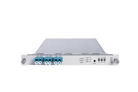
Enhance Your Network's Reach with GBIC SHOP's LH10 Optical Transceivers
Experience unparalleled connectivity with GBIC SHOP's LH10 optical transceivers. As your trusted online retailer of optical fiber components, we bring you the LH10 series for seamless, high-performance networking. Designed for long-haul applications, these transceivers ensure reliable data transmission over extended distances. Elevate your network's capabilities with GBIC SHOP's LH10 series - the epitome of efficiency and endurance. Don't compromise on quality; invest in the best. Purchase the LH10 optical transceivers online from GBIC SHOP today and empower your network with superior performance. Transform your connectivity - shop now for the future of data transmission
0 notes
Text
A Deep Dive into Design, Materials, and Applications of High-Frequency PCBs
In the fast-paced world of electronics, where new ideas drive progress, High-frequency PCBs stand out as crucial players. Think of them as super-skilled problem-solvers for handling challenges posed by high-frequency signals. Picture a world where 5G signals zip through the air, radar systems reveal hidden details, and medical gadgets get a clear view inside the human body. In this high-tech arena, HF PCBs take the stage, designed to keep up with signals at frequencies that go beyond what regular circuit boards can handle.
This article will break down HF printed circuit boards, explaining what they are, how they function, and the key things to consider when creating them.
What is High-frequency PCB?
If you need to work with signals that travel at very high frequencies, you need a HF PCB or High-frequency PCB. In contrast to conventional PCBs, HF PCBs offer superior performance in circumstances where signals operate in the high-frequency region. Conventional PCBs are often utilized for lower-frequency applications. The telecommunications industry, RF and microwave devices, and medical equipment are only a few examples of the many high-tech electronic fields that rely on these boards.
Modern technologies, such as 5G infrastructure, radar systems, RF transceivers, and high-frequency imaging devices, have high standards, and High-frequency printed circuit boards (PCBs) are able to achieve such standards. These boards can withstand harsh conditions with ease because of the meticulous craftsmanship that goes into their construction, which frequently makes use of cutting-edge methods like laser drilling.
Uses for High-Frequency Printed Circuit Boards:
Numerous state-of-the-art applications rely on High-frequency printed circuit boards. In the telecommunications industry, for example, HF PCBs are crucial for the installation of 5G networks and satellite communication systems. These circuit boards are essential to the operation of radar systems and RF transceivers, which are RF and microwave devices. Additionally, HF PCBs are utilized by medical equipment, such as MRI scanners and high-frequency imaging devices, to improve their performance.
Materials Used for High-Frequency PCBs:
Selecting the right materials, especially the dielectric and substrate materials, is crucial to the performance of HF PCBs. To keep signals intact and reduce signal loss, dielectric materials with low-loss characteristics are crucial. Materials such as PTFE and hydrocarbons packed with ceramic are commonly utilized. For high-frequency applications, substrate materials with little effect on signal integrity, including FR-4 and Rogers 4350, are excellent.
Capabilities of High-frequency PCBs:
The exceptional capabilities of high-frequency printed circuit boards distinguish them from their electronic counterparts. These board's ability to regulate impedance for high-speed communications and reduce signal loss makes signal integrity a strong suit. Thermal management is an additional critical component to solve the problem of heat dissipation in high-frequency applications. Improved performance and dependability of HF PCBs are achieved by the utilization of materials that exhibit high heat conductivity.
Knowing the essential features and achieving the necessary criteria of HF PCBs is crucial for maximizing their potential. Crucial to high-speed communications is trace geometry, which calls for regulated impedance traces and careful design. Different types of vias affect signal integrity; therefore, design is equally important. To achieve the best possible performance, it is crucial to carefully position the vias.
Considerations for PCB manufacturing:
From design to a fully working HF PCB, there are several steps in the manufacturing process. The strict specifications of high-frequency applications necessitate precise production with tight tolerances. It is common practice to use advanced production processes to attain the required level of accuracy. Environmental sustainability in printed circuit board (PCB) manufacturing is ensured by the careful selection of surface finishes and PCB fabrication that both adhere to RoHS regulations and do not compromise signal integrity.
High-frequency printed circuit boards are essential to contemporary electronics because they allow for improvements in areas such as medical equipment, telecommunications, and RF and microwave devices. These boards are designed to handle the rigorous requirements of high-frequency applications through careful material selection for the dielectric and substrate, as well as precise production processes. In the years to come, advancements in HF PCB technology will undoubtedly open up new avenues of opportunity and spur innovation in a wide range of sectors. The vital significance that HF PCBs play in defining the electrical world is shown by their path from design to manufacture.
Read More: A Deep Dive into Design, Materials, and Applications of High-Frequency PCBs
0 notes
Quote
The first thing is overall, our supply is improving. Overall, our supply chain is just doing an incredible job for us. Everything from, of course, the wafers, the packaging, the memories, all of the power regulators to transceivers and networking and cables, and you name it, the list of components that we ship. As you know, people think that NVIDIA GPUs is like a chip, but the NVIDIA Hopper GPU has 35,000 parts. It weighs 70 pounds. These things are really complicated things we've built. People call it an AI supercomputer for good reason. If you ever look at the back of the data center, the systems, the cabling system is mind-boggling. It is the most dense, complex cabling system for networking the world has ever seen. Our InfiniBand business grew 5x year-over-year. The supply chain is really doing fantastic supporting us. And so overall, the supply is improving. We expect the demand will continue to be stronger than our supply provides, and through the year and we'll do our best. The cycle times are improving and we're going to continue to do our best. However, whenever we have new products, as you know, it ramps from 0 to a very large number, and you can't do that overnight. Everything is ramped up. It doesn't step up. And so whenever we have a new generation of products and right now, we are ramping H200s, there's no way we can reasonably keep up on demand in the short term as we ramp. We're ramping Spectrum-X. We're doing incredibly well with Spectrum-X. It's our brand-new product into the world of Ethernet. InfiniBand is the standard for AI-dedicated systems. Ethernet with Spectrum-X, Ethernet is just not a very good scale-out system. But with Spectrum-X, we've augmented, layered on top of Ethernet, fundamental new capabilities like adaptive routing, congestion control, noise isolation or traffic isolation so that we could optimize Ethernet for AI. And so InfiniBand will be our AI-dedicated infrastructure, Spectrum-X will be our AI-optimized networking, and that is ramping. So we'll -- with all new products, demand is greater than supply. And that's just kind of the nature of new products, and we work as fast as we can to catch up with the demand. But overall, net-net, overall, our supply is increasing very nicely.
Aiera | Events | Q4 2024 NVIDIA Corp Earnings Call - Q&A
Demand high and supply is improving #Tech
0 notes
Text
FIBER OPTICAL SOLUTION
Fiber Optical Communication Solution is a comprehensive and advanced system designed for efficient and reliable data transmission over long distances. It consists of various components such as fiber optic cables, transceivers, optical amplifiers, and multiplexers. This solution offers high-speed data transfer, wide bandwidth, and low latency, making it ideal for telecommunications, internet service providers, and corporate networks.
ODN Network
Optical Distribution Network (ODN for short). ODN is an FTTH optical cable network based on PON equipment. Its role is to provide optical transmission channels between OLT and ONU. In terms of function, ODN can be divided into four parts: the feeder optical cable subsystem, the distribution optical cable subsystem, the home line optical cable subsystem and the optical fiber terminal subsystem from the central office end to the user end.
Fiber Optic Solution for Triple Play Network
Triple Play Network
In short, the "Triple Play Network" are the integration between cable television, telecommunications and computer communication. The purpose is to build a sound and efficient communication network to meet the needs of social development. The three-network integration has high requirements for the application practice of technology. In the future, mobile phones can watch TV and surf the Internet. TV can call, Internet access, and computer can also call and watch TV.
Fiber Optic Solution for Telecommunication
Telecommunication
Telecommunication refers to the use of electronic technology to pass information between different places. Telecom includes different types of long-distance communication methods, such as: radio, telegraph, TV, telephone, data communication, and computer network communication. Telecom is an important pillar of an information society.
Fiber Optic Solution for Data Center
Data Center
Internet data center (IDC) refers to a comprehensive device (including high-speed Internet access bandwidth, high-performance LAN, safe and reliable computer room environment, etc.), professional management, and perfect application service platform. Based on this platform, IDC service providers provide customers with Internet basic platform services (server hosting, virtual hosting, mail cache, virtual mail, etc.), and various value-added services (rental services, domain name system services, load balancing systems, database systems, data backup services, etc.).
Fiber Optic Solution for FTTH
FTTH
Fibre (Fiber) to the Home (FTTH) is a transmission method for optical fiber communication. Specifically, FTTH refers to installing the optical network unit (ONU) at home users or business users. It is the optical access application type of the optical access to the user except FTTD (optical fiber to the desktop). The significant technical characteristics of FTTH are not only providing greater bandwidth, but also enhance the transparency of the network for data format, rate, wavelength, and protocols, relax the requirements of environmental conditions and power supply, and simplify maintenance and installation. PON technology has become a hot spot for global broadband operators, and is considered one of the best technical solutions to realize FTTH.

0 notes
Text
Optical Transceivers: The Backbone of High-Speed Fiber Optic Networks
In the age of rapid data exchange and ever-expanding digital networks, the demand for high-speed and reliable data transmission has never been greater. Fiber optic networks have emerged as the preferred choice for meeting these demands due to their capacity for lightning-fast data transmission and immense bandwidth capabilities. At the heart of these networks lies the unsung hero: the optical transceiver. This vital component, often overlooked but indispensable, serves as the bridge between electrical and optical signals, making high-speed data communication possible. In this article, we delve into the critical role of optical transceivers and the importance of selecting a trusted optical transceiver manufacturer.
Optical transceivers are the linchpin of fiber optic networks, as they facilitate the conversion between electrical signals, which our devices understand, and optical signals, which fiber optic cables transmit. These small yet powerful devices house intricate electronics and optics that enable the modulation and demodulation of data into and out of light pulses, ensuring that data can travel vast distances at incredible speeds. They come in various form factors and configurations, tailored to the specific needs of different network applications.
One of the key considerations when it comes to optical transceivers is the choice of manufacturer. A reputable optical transceiver manufacturer plays a pivotal role in ensuring the reliability and performance of a fiber optic network. Here are some critical factors to consider when selecting an optical transceiver manufacturer:
Quality Assurance: A trustworthy manufacturer adheres to rigorous quality control standards, conducting thorough testing and inspection of each transceiver unit. This commitment to quality minimizes the risk of premature failure and ensures consistent performance over the lifespan of the transceiver.
Compatibility: A reliable manufacturer produces optical transceivers that are compatible with a wide range of network equipment from various vendors. Compatibility is crucial for seamless integration into existing network infrastructure.
Performance Specifications: Look for manufacturers that provide detailed performance specifications for their transceivers, including data rates, reach, and power consumption. This information helps network administrators make informed decisions about which transceivers best suit their network requirements.
Warranty and Support: Manufacturers that offer robust warranties and excellent customer support provide peace of mind for network operators. A manufacturer's willingness to stand behind its products reflects confidence in their reliability.
Customization Options: Depending on the specific needs of a network, customization options may be essential. Reputable manufacturers can often tailor transceivers to meet unique network requirements, ensuring optimal performance.
Environmental Considerations: Energy efficiency and eco-friendliness are increasingly important considerations. Some manufacturers design transceivers with lower power consumption, contributing to greener and more sustainable network operations.
Cost-Effectiveness: While quality should never be compromised, cost-effectiveness is still a vital factor. Reliable manufacturers offer competitive pricing without sacrificing performance or reliability.
In summary, optical transceivers are the unsung heroes that enable the high-speed and reliable data transmission that underpins our modern digital world. When selecting an optical transceiver manufacturer, it's crucial to prioritize factors such as quality assurance, compatibility, performance specifications, warranty and support, customization options, and environmental considerations. A trusted optical transceiver manufacturer not only ensures the seamless operation of fiber optic networks but also contributes to the overall efficiency, reliability, and sustainability of network infrastructure. In an era where connectivity is king, the right choice of optical transceivers and manufacturer can make all the difference.
1 note
·
View note