#EMCProtection
Explore tagged Tumblr posts
Visit Tumblr Blog
Explore Tumblr blogs with no restrictions, modern design and the best experience.
Last Seen Tumblr Blogs


Fun Fact
Tumblr has a 66 index score for customer satisfaction in the US.
Text
FASTRON's Common Mode Filter Chip Inductors are designed to protect differential signal paths from common mode disturbances, making them ideal for applications such as data-line filters, Ethernet networking, CAN-Bus, USB, and EMC circuit protection. With inductance ranges from 11 µH to 100 µH and rated DC currents between 150 mA and 300 mA, these inductors ensure efficient noise suppression in various electronic circuits.
#CommonModeFilters#ChipInductors#NoiseSuppression#EMCProtection#FASTRON#DataLineFilters#CircuitDesign#ElectronicComponents
0 notes
Text
What ESD device should I use for 3.7V Li-Ion surge protection?
In the rapidly developing TWS and smart wearable market, limited by the size of the product and the threat of static electricity and surges in the instant of the battery contact switch, a precise protection of the ESD device is needed to ensure the safety of the power supply IC, from static electricity, surge threats.

The product supports surge 45A, and maintains a margin, support surge voltage greater than 100V, in harsh environments can also be guaranteed to work normally.
Compared with ESD5651N-2/TR, Leiditech Electronics has a greater ipp capability of 1 0A current and a better delivery time, please request samples.
Leiditech Electronics is committed to becoming a leading brand in electromagnetic compatibility (EMC) solutions and component supply. We offer a wide range of products, including ESD, TVS, TSS, GDT, MOV, MOSFET, Zener diodes, and inductors. With an experienced R&D team, we provide personalized customization services to deliver the highest quality EMC solutions tailored to our customers’ needs.
If you’d like to learn more or have any questions, don’t hesitate to reach out:
Visit us at [en.leiditech.com]
#EMCProtection #ESDSafety #WearableTech #Leiditech #SmartDevices #SurgeProtection #ElectronicsDesign #BatterySafety #TWSInnovation #PowerProtection #IoTSecurity #TechSolutions #LiIonBattery #ElectronicsEngineering
0 notes
Text
EMC Design Pit Avoidance Guide:
Four no mnemonics
Why does your well-designed product fail EMC testing? The EMC team at Leiditech shares 4 practical EMC design techniques summarized in the “Four No” principles to help you avoid common pitfalls!
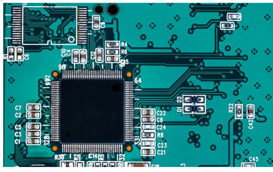
Principle 1: Make Current Take the Shortest Path, Not a Detour
Core Logic: High-frequency currents follow the “path of minimum inductance”. Larger loops → stronger radiation!
Key Insights from Leiditech Lab:
l Signal currents must form closed loops, with return paths closely following the outgoing paths.
l Low-frequency (kHz-level) currents follow the “path of minimum resistance”, with possibly dispersed return paths; high-frequency (MHz-level) currents follow the “path of minimum inductance”, with return paths closely adhering to the main trace.
l Design Tip: Place high-speed signals adjacent to their return planes and reduce the spacing between the signal layer and the ground plane.
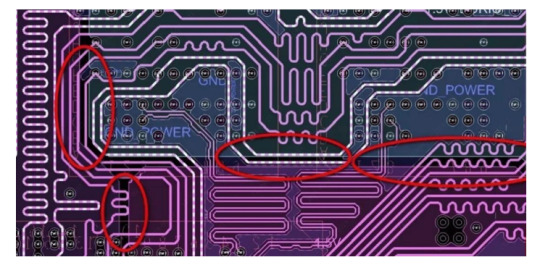
Principle 2: Do Not Split the Signal Return Plane
Leiditech EMC engineers’ golden rule: Provide a complete return plane for all signal currents. For low-frequency signals prone to interference or likely to cause board-level interference, use dedicated trace layers to route return currents back to the source rather than splitting the plane. Arbitrary slotting/dividing the ground plane can cause abrupt changes in return paths → surging EMI!
Exceptions:
Independent return traces may be used only for isolating low-frequency sensitive signals (e.g., audio power supplies), provided:
l The independent layer has a separate return path and does not cross high-frequency planes.
l Consult Leiditech EMC experts to avoid case-by-case misapplication.
Warning: A complete plane is the optimal solution in 99% of scenarios!
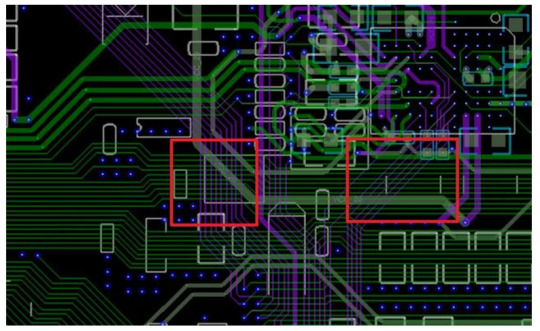
Principle 3: Do Not Route High-Speed Circuits Between Connectors
This is one of the most common issues in PCB designs evaluated by Leiditech Lab. Many simple designs that could easily meet EMC requirements (with no extra cost or effort) end up requiring extensive shielding and filtering due to violating this rule.
Why connector placement matters: At frequencies below several hundred MHz, wavelengths can be meter-scale or longer. While the PCB itself acts as a low-efficiency “antenna” due to its small electrical size, cables or external devices connected to the PCB can become efficient radiators.
When signal currents flow on traces and return through a complete plane, the voltage difference between any two points on the plane is typically proportional to the in-plane current. When all connectors are aligned along one side of the PCB, voltage differences between them are negligible. However, if high-speed circuits are routed between connectors, potential differences of several millivolts or more may arise, driving currents into connected cables and causing excessive radiation emissions.
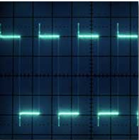
Principle 4: Do Not Blindly Pursue the Fastest Edge; Control Signal Transition Time
Fast edges (1ns) → harmonics up to 2GHz; slow edges (5ns) → harmonics <500MHz.
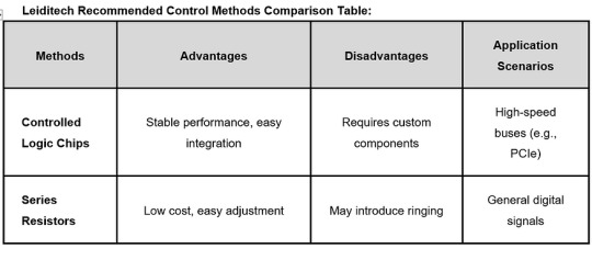
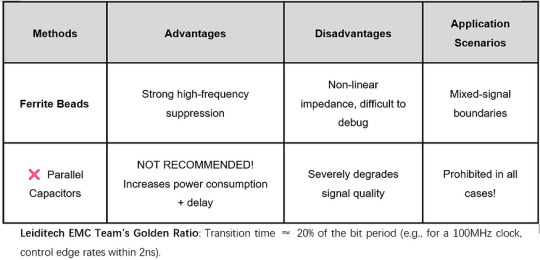
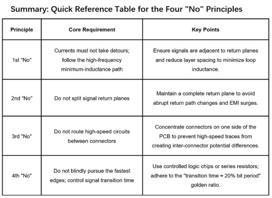
Leiditech EMC Team’s Golden Ratio: Transition time ≈ 20% of the bit period (e.g., for a 100MHz clock, control edge rates within 2ns).
Leiditech Electronics is committed to becoming a leading brand in electromagnetic compatibility (EMC) solutions and component supply. We offer a wide range of products, including ESD, TVS, TSS, GDT, MOV, MOSFET, Zener diodes, and inductors. With an experienced R&D team, we provide personalized customization services to deliver the highest quality EMC solutions tailored to our customers’ needs.
If you’d like to learn more or have any questions, don’t hesitate to reach out: 📧 [[email protected]] 🌐 Visit us at [en.leiditech.com] #NoMoreBuzzing #DriveInPeace #SmartCarTech #ElectromagneticShield #AutoInnovation #CarSafetyFirst #ShanghaiLeditech #NextGenDriving #HornHarmony #AutoElectronics #EMCProtection #StaticNoMore #SmartDriveSolutions
0 notes