#FEA evaluation
Explore tagged Tumblr posts
Visit Tumblr Blog
Explore Tumblr blogs with no restrictions, modern design and the best experience.
Last Seen Tumblr Blogs


Fun Fact
Tumblr was named as a finalist in Lead411’s New York City Hot 125 in Aug 2010.
Text
There is something really freeing about having the MORGUE FILES work and being able to fling my years old incomplete stuff into it. Been going through a whole slog of my NY-era WIPs and picking out the most complete outlines to toss into there.
#got a couple of One Piece stuff#some FMA outlines that I think are complete enough#maybe some Bleach#though I probably need to dig up come high schools notes to finish typing up the outlines#whole bunch of FEA I need to evaluate
1 note
·
View note
Text

I have been thinking about this ask since I got it and as to the question of why John treated people the way he did, especially Paul. My take on this situation is that John Lennon was not allowed to grow up by the environment and people he was surrounded by and so he could not envision the future consequences of his actions the way that the average adult can. This with the addition of his constant drug use (which in all likelihood left him with significant brain damage) meant that he could not function the way an adult should.
John actually did have periods of emotional growth where he looked inward, changed, and tried to do better. These moments took place before he got famous, when he was faced with adversity and he rose to meet it.
IMO Hamburg 1960 was such a time. John partied, he found new pills to take, he experimented with kissing and shagging men, he discovered transgender people (and shagged them), and had a lot of ups and downs with his boyfriend(s) and his group. It is easy to dismiss this as mindless hedonism but as a retired hedonist myself (though I never pushed as hard as John did) I will tell you: hedonism can lead to introspection and self knowledge. John really pushed it to its limits and he almost lost Paul because of it but I think the Great Unknown that happened in Hamburg pushed John to actively change. He cleaned himself up a bit especially once Stuart left to be with Astrid. Once he came back to Liverpool (after enduring the trauma of his bandmates being ripped from him, yet another violent separation that no doubt would have left him in an emotional tailspin) he rested, hooked up with Cynthia, and then went looking for Paul knowing that he needed him to make this band thing work. Like, John spent a few weeks in his bedroom not speaking to anyone once he went home. He didn't want to be seen, he wanted to sleep and eat hot food, and think. He was considering whether he should continue with the band or not, if this was really worth it. Which implies there was a precarious moment where John was thinking of just ending The Beatles. He decided that the plan still had merit, ran into George, and then went to fetch Paul. A few months of light groveling and nagging later, Paul was his again. John committed to The Beatles and therefore committed to Paul. Paris was the culmination of this change and John's reward for putting in the work, and from what we can gather, Paul made every inch worth John's while.
The Beatlemania years leading up to Sgt. Pepper and psychedelia. This was period is more like 1961-1965 Shea Stadium. From here it was an upward climb and subsequently the most intense period of his relationship with Paul. I don't think this was just youthful enthusiasm and the flush of a new relationship, I think John was learning and growing as a person thanks to this adversity. He bonded even closer to Paul which resulted in their intimacy deepening; John's songwriting matured and culminated in "Ticket to Ride" which is a brutal self evaluation of his own faults and how he drives his loved ones away from him. You don't write a song like "Ticket to Ride" because you have no idea what it's like for your lover to get fed up with your moodiness and leave you. John was much more self aware than he's given credit for. This continued onward, them thinking they've reached the summit only to find there's a new height to climb. John said something to the effect of "I saw the top of the mountain" as a result of the first Shea concert. (They would do a second Shea concert in 1966.) That was when he realized that The Beatles were it and that they were not vacating the number one spot any time soon. What else was there to strive for?
And I think after that, a lot of John's emotional development kind of...stopped. Or was held up. Or slowed down to a snail's pace, whichever you prefer. The LSD had a hand in this, tripping constantly takes a lot out of you. Yesterday played its part, John emotionally retreated out of fear of losing Paul (which of course ensured that he lost Paul forever). Success becomes your enemy sometimes; John had so much success that he no longer had to face adversity, no longer had to grow because everything he wanted was on tap. As someone somewhere said, fame ruined the Beatles in this way.
That's the crux of it, I think. He just stopped maturing. It was childish the way he slagged off Paul -- not just Paul but other people as well. Sean said that John spent the rest of his life apologizing to everyone he ran into because of Lennon Remembers, which implies he burned a lot of bridges with that one. John had a habit of doing that and his fame as a Beatle enabled him to do it without consequences. No one was willing to stand up to him so he didn't get to learn a pattern of "don't do this or else this will happen." He was mentally damaged from his drug usage and I also wonder if he had a genuine learning disability of some kind because he simply could not make the connection between cause/effect: "If I do X then Y might happen so I shouldn't do X." His mother was not a drug user like John but she exhibited many of the same behaviors he did. Namely the "inability to visualize consequences" thing.
John did care about Paul, especially when it was starting out. I think the love was pure then because his mental aesthetic of who and what Paul was had not yet been distorted. John knew who Paul was, he knew who John Lennon was, they were in love and everything was possible.
But then John's untreated mental illness begins to take its toll, he's self medicating with drugs which does more harm than good, his mental aesthetic of Paul distorts more and more because Paul will not let him in. The media did this to John too, all of them reporting on how cool Paul was and how amazing Yesterday is and John is shitting himself internally because he can feel the split already forming between them musically. John is unable to stop himself from manipulating Paul in response, which is a bad move because Paul is the ultimate contrarian and bolts in response. Which sends John into deeper panic etc. And oh yes, the entire world is watching them while this happens and nitpicking their every move. We live in the age of social media, we know what this is like.
Over time that love became mixed in with anger and resentment. John could not tell fantasy from reality. He did what he always does and he imagined something, tricked himself into believing it, and then got mad about something that didn't exist. If he did reach out to Paul then Paul responded badly, which understandably devastated John's feelings.
When you show someone your real feelings and they dismiss you or trivialize your vulnerability because they want to Win At Being Right...your relationship crumbles with that person. A common bug in Paul's relationships is that he needs to Win At Being Right even at the expense of people loving him. We don't know this for sure but I'm convinced he did this to John plenty of times. Frankly, a relationship cannot survive that behavior. Lack of mutual respect kills marriages all the time. I absolutely believe that Paul disrespected John and trivialized his feelings (even if by accident) and that this caused John to become bitter over time since Paul took him for granted. Who wouldn't become bitter under those circumstances?
This is how they got into the "fuck you/no, please, fuck you/no no no fuck YOU/I absolutely insist, you must go fuck yourself" cycle. Which John really just expanded on during the 1970s with his bitching about Paul, it was just another level of the "fuck you bitch" cycle that started between them with Yesterday. And John's immaturity and brain damage from drug usage and his inability to understand consequences meant that he didn't fully comprehend what he was doing. He didn't want to think that Paul was vulnerable because Paul had rejected John's vulnerability. He didn't want to imagine he was hurting Paul deeply because Paul had hurt him deeply. He wanted revenge on Paul more than he wanted to keep his relationship with Paul because he thought Paul wouldn't be too damaged by it. I think John had gotten comfortable with the idea that no matter what he threw at Paul, Paul would not only survive it but that he'd rub John's face in it. I don't think John ever considered the idea that he could actually succeed in what he was doing, he never imagined that he would actually win the argument and that he would damage Paul's image and John's relationship with Paul forever. That sense of "I'll lose no matter what" enabled him to act out however he wanted because it wasn't like any of it would matter anyway, right? Paul can survive anything. He's invincible.
Right?
John did love Paul, I believe that. I think he loved Paul deeply and sincerely. I think if he actually understood what Paul was thinking and feeling then John would have changed tactics immediately or even stopped what he was doing. But John's drug usage, years of slights and disrespect from Paul, being unable to visualize consequences, and immaturity caused him to act out in a childish way. He stopped listening to Paul and started listening to his resentments and grudges. Lashing out at Paul was the only outlet he had and John didn't know how to do anything else. He had no incentive to learn otherwise and grow up, deal with Paul on adult terms.
Funnily enough I think it's actually losing George that finally set something into motion inside John. Like, George cut John off, an extremely big deal. In my neck of the woods its called "severing" and its probably the most difficult thing you can possibly do with any sort of relationship. George ignored John; he cut John out of his autobiography; he stopped talking to John; he did not mention him in public. He knew this was the most brutal punishment he could devise for John Lennon and it worked. John wrote "lost" by George's name in the word association game. John went too far bitching about Bob Dylan and not apologizing for hanging George out to dry. George had enough and did the right thing. He severed his relationship with John because John was toxic and dragged George down. Of all the people in John's life, George is the one who willingly served consequences to John when he was surrounded by enablers and errand boys.
That, more than anything, seems to be what set John on the back foot. I sincerely believe that George cutting him off forced John to do some introspection and that is part of what he was doing in the Dakota after Sean was born. Asking himself what he did to make George cut him off; and then John slowly started to grow and mature again. Because you see, George provided what Paul couldn't: he gave John adversity to meet, which forced John to grow as a person. And so we got the song "Woman" which is not just about the women in John's life but is also a letter to all the people he hurt with his thoughtlessness and immaturity, where he finally starts taking responsibility for his actions:
I can hardly express, My mixed emotion at my thoughtlessness, After all I'm forever in your debt,
I will try to express, My inner feelings and thankfulness, For showing me the meaning of success,
hold me close to your heart, However distant don't keep us apart, After all it is written in the stars,
please let me explain, I never meant to cause you sorrow or pain, So let me tell you again and again and again,
It's on par with "Ticket to Ride" and "I Know, I Know" in John showing introspection and discussing his own flaws. Something that he notably was not doing during his peak "fuck you Paul" era.
John loved Paul but also resented him due to their circumstances. He wanted to hurt Paul but didn't think he could actually do so because his mental aesthetic of Paul was so viciously distorted. He dehumanized Paul by putting him on a pedestal, made him an object John could degrade at a moment's notice to make himself feel better. You can do that to objects without consequences; when you do it to people, you get pushback.
Losing George and Paul keeping him at a distance for years is what made John finally realize that he had hurt them and that he could hurt them to the point that he would never see them again. It took years of self examination for John to come to this realization which indicates how disordered and muddy his thinking was.
135 notes
·
View notes
Text
Automated Testing vs. Manual Testing: Which One is Right for Your Project?

Achieving high-quality, reliable software stands as a fundamental requirement in software development. Successful testing functions as an essential tool to discover faults and build performance capabilities that create better user experience outcomes. Two main testing methods dominate the field: automated testing and manual testing. The process of quality software assurance uses different testing approaches that demonstrate their own advantages as well as weaknesses according to specific project requirements and scenarios. We will explore the specifics to determine which testing process works best for your system development efforts.
1. What Is Manual Testing?

Manual testing involves a human tester manually executing test cases without using automation tools. Key Characteristics:
The methodology focuses its efforts on user interface together with usability and experience testing.
Human-centered applications where selection requires discretion include ad hoc testing and enumerative testing as well as examinations that need human evaluation.
Human performers are required during this approach; thus, it demands substantial time.
2. What Is Automated Testing?

Software performing automated testing executes test cases through workflows and helpers. Key Characteristics:
Efficient for repetitive and regression testing.
Users must spend money on tools along with developing custom scripts for testing.
Reduces human error.
3. Advantages of Manual Testing

Human Intuition: Software testing professionals can detect kernels through their human cognitive ability that automated tools cannot match. The observation and evaluation of visual elements runs more efficiently through human operatives instead of advanced tools.
Flexibility: This method suits exploratory testing specifically because there are no pre-determined scripts available.
Low Initial Investment: Running this approach does not need tool purchases or applications to develop automation frameworks.
Adaptable for UI/UX Testing: Running this approach does not need tool purchases or applications to develop automation frameworks.
4. Advantages of Automated Testing

Speed: Executes repetitive tests much faster than humans.
Scalability: The system proves most effective for extensive projects that need constant system updates.
Accuracy: When performing recurring actions, automated systems minimize the chances of human mistakes.
Cost-Efficient in the Long Run: Once established and implemented, the system demands costly investments but ensures continuous development expenses decrease over time.
Better for CI/CD Pipelines: Such testing technology connects various development pipelines that support agile and DevOps methodologies.
5. Disadvantages of Manual Testing

Time-Consuming: The manual performance of repeated tests leads to delayed completion of projects.
Error-Prone: Large applications contain tiny bugs that human testers commonly fail to detect.
Not Ideal for Scalability: The process of increasing manual testing needs additional testers to avoid cost escalations.
6. Disadvantages of Automated Testing

Initial Costs: Organizations must provide high financial resources to procure testing tools together with developing programming constructs.
Limited to Pre-Defined Scenarios: These testing approaches work poorly for handling exploratory or ad hoc testing.
Requires Maintenance: Test scripts need frequent updates when application changes occur.
Not Suitable for UI/UX Testing: Struggles with subjective user experience evaluations.
7. When to Use Manual Testing

Small Projects: The testing method proves beneficial at a low cost for small applications and provides quick assessments.
Exploratory Testing: Testing this approach benefits projects whose scripts have not been defined yet or need evaluation for newly added features.
Visual and Usability Testing: Performing assessments on interface components together with design features.
8. When to Use Automated Testing

Large Projects: Handles scalability for projects with frequent updates.
Regression Testing: Program testing becomes more efficient through automation since automated assessments perform multiple tests following each update process.
Performance Testing: The system performs efficient capabilities to conduct load testing and stress testing.
Continuous Development Environments: Agile progression and DevOps implementations need automation as a core requirement.
READ MORE- https://www.precisio.tech/automated-testing-vs-manual-testing-which-one-is-right-for-your-project/
2 notes
·
View notes
Text
Evaluating the Impact of Water Hammer During Emergency Shut-Off Operations

Understanding the Scope:
The situation examined involves an abrupt closure of a valve, which brings the fluid velocity to an immediate halt. This sudden stoppage generates a pressure surge or pulse that travels in the opposite direction through the pipeline. The propagation of this pressure wave induces vibrations and repetitive mechanical stress, especially around vulnerable regions such as bends and Tee joints.
The result? Potential fatigue failure if not mitigated.
Simulation Strategy: Coupled CFD + FEA Approach:
To analyze the problem with high fidelity, we adopted a coupled Computational Fluid Dynamics (CFD) and Finite Element Analysis (FEA) methodology:
1.Transient CFD Analysis: Pressure surges were captured with time resolutions as fine as hundredths of a second.
2.FEA for Vibration Analysis: The time-dependent pressure data from the CFD model was used as input for structural analysis, highlighting stress and deformation patterns.
The synergy between CFD and FEA allowed us to not only visualize pressure pulses but also predict mechanical response and fatigue life under transient load conditions.
Key Observations from CFD:
By examining pressure contour plots at time intervals ranging from 0.01 to 0.07 seconds, we observed:
1. Strong reverse-traveling pressure waves, initiated by the instant valve closure. 2. Pressure amplification at pipe bends, confirming them as critical stress concentrators. 3. Formation of shock zones, potentially leading to local material failure if not addressed.

Structural Insights from FEA:
Using the von Mises stress criteria and guided by ASME Code Section VIII Div. 2, we conducted:
1. Stress Localization Analysis: Bends and discontinuities showed signs of crack initiation under repeated loading. 2. Fatigue Life Prediction: Using standardized fatigue design formulas, we estimated that the system can withstand approximately 318,800 cycles under the simulated loading conditions.

Design Recommendations:
Based on the results, we provided design-level suggestions: 1. Geometry modifications at bends to reduce stress concentrations. 2.Material upgrades in fatigue-prone zones. 3.Inclusion of surge mitigation systems, such as dampers or slow-closure valves.
These measures can significantly extend the operational life and integrity of pipeline systems facing emergency shut-down scenarios.
Final Thoughts:
This case study highlights the necessity of high-resolution transient analysis for systems exposed to water hammer conditions. At Graphler Technology Solutions, we leverage advanced CAE tools to predict, visualize, and solve complex mechanical-fluid interactions, ensuring safer and more reliable engineering systems. We are also known for CFD consulting services , stress analysis services, structural analysis services, and structural design services.
For organizations operating in sectors such as oil & gas, water treatment, or industrial manufacturing, integrating such simulation strategies can be the difference between robust design and unexpected failure.
0 notes
Text
Unlocking Manufacturing Excellence: How Simcenter Femap Streamlines Your Production Process
In today's highly competitive manufacturing landscape, efficiency, innovation, and cost-effectiveness are paramount. Companies are constantly seeking ways to optimize their processes, reduce time-to-market, and deliver superior products. This is where advanced simulation software like Simcenter Femap comes to the rescue! Simcenter Femap, a leading pre- and post-processor for finite element analysis (FEA), empowers engineers to virtually test and refine designs, predict performance, and identify potential issues long before physical prototyping begins. This translates directly into a streamlined manufacturing process, leading to significant gains across the board.
What Simcenter Femap?
Simcenter Femap is not just a software; it's a comprehensive pre- and post-processor for finite element analysis (FEA) that empowers engineers to virtually model, analyze, and optimize product designs before ever building a physical prototype.
Using Femap’s digital simulation capabilities you can:
Predict and improve product performance and reliability
Reduce time-consuming and costly physical prototyping and testing
Evaluate different designs and materials
Optimize your designs and reduce material usage
Simcenter Femap Software Comes to the Rescue!
In essence, Simcenter Femap transforms the manufacturing process from a reactive, problem-solving approach to a proactive, predictive one. It empowers engineers to make informed decisions earlier, leading to superior product designs and a more efficient, cost-effective manufacturing pipeline. Whether it's structural integrity, thermal performance, or dynamic response, Femap provides the tools to simulate the real world accurately, ensuring your products are ready for success.
Why Choose DDSPLM?
When it comes to implementing and maximizing the benefits of Simcenter Femap, choosing the right partner is crucial. DDSPLM Private Limited stands out as a reliable and experienced Siemens Expert Partner, offering a distinct advantage:
Proven Expertise
Industry-Specific Solutions
Comprehensive Support and Training
Focus on Digitalization and Industry 4.0
Strong Customer Endorsements
Conclusion
Simcenter Femap software is an indispensable tool for modern manufacturing, enabling businesses to innovate faster, reduce costs, and deliver higher-quality products. Its advanced simulation capabilities allow for virtual prototyping, comprehensive analysis, and design optimization, fundamentally streamlining the entire product development lifecycle.
By partnering with an experienced and dedicated expert like DDSPLM, you not only gain access to this powerful software but also benefit from their in-depth knowledge, tailored solutions, and unwavering support. Embrace the power of Simcenter Femap with DDSPLM, and take a significant leap towards manufacturing excellence and sustained success in today's dynamic global market.

0 notes
Text
Application of Captive Load Testing in Aircraft Wing Load Analysis
In the aerospace industry, ensuring the structural integrity and safety of aircraft components is paramount. One critical aspect of this is the testing and validation of aircraft wings, which endure significant aerodynamic loads during flight. Among the various testing methodologies, Captive Load Testing (CTS Testing) has emerged as a crucial technique for accurately assessing wing load responses under controlled conditions. This article explores the application of Captive Load Testing in aircraft wing load analysis, highlighting its importance, methodology, benefits, and real-world applications.
Understanding Aircraft Wing Loads
Aircraft wings are primary load-bearing components designed to generate lift and support the weight of the aircraft during flight. Wings experience a wide range of loads, including aerodynamic forces, inertial loads during maneuvers, gust loads, and ground handling stresses. These loads vary dynamically and can cause complex stress distributions throughout the wing structure.
Accurate assessment of wing load response is essential to:
Ensure structural safety and reliability
Optimize wing design for weight and performance
Comply with certification standards set by aviation authorities
Predict the lifespan and maintenance needs of the wing
Traditional analytical and computational methods, such as finite element analysis (FEA), provide valuable insights, but physical testing remains indispensable for validation.
What is Captive Load Testing?
Captive Load Testing (CTS Testing) is a testing methodology used to apply controlled loads to a component or structure in a fixed setup, often referred to as "captive," because the test specimen is restrained or supported in a specific test fixture. Unlike free or full-scale flight testing where loads vary uncontrollably, captive load testing allows precise application and measurement of loads in a repeatable environment.
In the context of aircraft wings, captive load testing involves mounting a wing or wing section in a test rig where hydraulic actuators or mechanical devices apply loads that simulate aerodynamic forces experienced during flight. The wing is instrumented with strain gauges, displacement sensors, and other instrumentation to record its response.

Objectives of Captive Load Testing in Wing Load Analysis
The primary goals of captive load testing for aircraft wings include:
Validation of Design Assumptions: Verifying that the wing structure behaves as predicted by design models under simulated load conditions.
Structural Integrity Assessment: Identifying any weak points, stress concentrations, or potential failure modes.
Certification Support: Providing evidence to aviation authorities such as the FAA or EASA that the wing meets safety and durability requirements.
Damage Tolerance Evaluation: Understanding how cracks, corrosion, or fatigue affect load carrying capacity.
Material and Component Testing: Evaluating performance of composite materials, fasteners, and bonding under load.
The CTS Testing Setup for Aircraft Wings
A typical captive load testing setup for aircraft wings consists of:
Test Fixture or Rig: A large, robust frame designed to hold the wing securely in place while allowing controlled application of loads at various points.
Load Application System: Hydraulic actuators or servo-controlled mechanical devices that apply forces and moments to simulate aerodynamic and inertial loads.
Instrumentation: A network of strain gauges, displacement transducers, accelerometers, and sometimes acoustic emission sensors attached to critical areas of the wing to monitor structural response.
Data Acquisition System: High-speed data recorders and analysis software collect and process the sensor data for real-time monitoring and post-test evaluation.
Depending on the wing size and test objectives, captive load testing can be conducted on full-scale wings, subassemblies, or scaled-down models.
How Captive Load Testing is Conducted
The process of captive load testing on aircraft wings typically follows these steps:
1. Preparation and Instrumentation
The wing or wing section is prepared by installing sensors at predetermined locations based on structural analysis. Strain gauges measure surface strain, while displacement sensors track deflections.
2. Mounting
The wing is carefully mounted in the test rig, ensuring alignment and support points simulate real-world boundary conditions such as fuselage attachments.
3. Load Application
Using hydraulic actuators, loads are applied incrementally to simulate various flight conditions, including:
Static loads representing steady-state flight
Gust loads simulating atmospheric turbulence
Maneuver loads from sharp turns or sudden pitch changes
Each load case is applied under controlled conditions while continuously monitoring wing response.
4. Data Collection and Analysis
Sensor data is collected throughout the test, allowing engineers to observe strain distribution, deflections, and any signs of structural distress. This data is compared against predicted values from computational models.
5. Post-Test Inspection
After load application, the wing undergoes detailed inspections for cracks, delaminations, or other damage. Sometimes non-destructive testing methods like ultrasonic or X-ray inspection are used.
Benefits of Using Captive Load Testing in Wing Load Analysis
There are several advantages to incorporating captive load testing in the wing design and certification process:
Accuracy and Repeatability
CTS Testing provides a controlled environment where loads can be precisely applied and repeated. This reduces variability and allows detailed assessment of wing behavior under specific load cases.
Early Detection of Structural Issues
Captive load testing can reveal stress concentrations and potential failure points before full-scale flight testing, reducing risks and development costs.
Validation of Computational Models
Physical test data serves to validate and calibrate computational models such as finite element models, improving their predictive accuracy for future designs.
Supports Certification and Compliance
Regulatory agencies require evidence of structural safety. CTS Testing provides robust, traceable data to support airworthiness certification.
Testing of Repair and Modification Effects
After repairs or structural modifications, captive load testing can assess if the wing maintains its load carrying capability.
Challenges and Limitations
While Captive Load Testing offers numerous benefits, it also comes with challenges:
High Cost and Complexity: Building test rigs and conducting tests on large wings can be expensive and resource-intensive.
Scaling Issues: For very large wings, testing full scale may be impractical, requiring scaled models and extrapolation.
Boundary Condition Replication: Perfectly simulating in-flight constraints on the wing in a fixed test rig can be difficult.
Limited Load Cases: Some complex dynamic loads experienced in flight may be hard to replicate precisely.
Despite these challenges, captive load testing remains a cornerstone in structural testing for aviation.
Real-World Applications and Case Studies
Example 1: Boeing 787 Dreamliner Wing Testing
During the development of the Boeing 787, captive load testing played a critical role in validating the composite wing design. Engineers applied simulated flight loads to full-scale wings to measure strain and deflection, confirming that the novel materials and structure met design expectations.
Example 2: Airbus A350 Wing Load Validation
Airbus employed captive load testing extensively for the A350 wing, which uses advanced composite materials. The testing helped verify the wing’s ability to handle gust loads and ensured compliance with stringent certification standards.
Example 3: Military Fighter Aircraft
Military aircraft wings undergo rigorous CTS Testing to ensure they can withstand extreme maneuver loads. For example, the F-35 Lightning II wings were tested under captive load conditions to validate structural integrity before flight trials.
The Future of Captive Load Testing in Aviation
With advances in materials science, aerospace design, and sensor technology, captive load testing continues to evolve:
Integration with Digital Twins: Real-time data from CTS Testing feeds digital twin models for improved predictive maintenance and design optimization.
Enhanced Sensor Networks: Wireless and fiber optic sensors enable more detailed and distributed monitoring of wing structures.
Automated Test Systems: Robotics and AI help automate load application and data analysis, increasing efficiency and accuracy.
Composite and Hybrid Structures: As composites become dominant, CTS Testing adapts to characterize their unique failure modes and load responses.
Advances in Sensor Technology and Data Acquisition for Captive Load Testing
One of the key drivers behind the evolution of Captive Load Testing (CTS Testing) in aviation is the rapid advancement in sensor technology and data acquisition systems. Historically, wing load testing relied heavily on strain gauges and displacement sensors connected via wired systems, which had limitations in terms of sensor placement, wiring complexity, and data fidelity.
Fiber Optic Sensors
Fiber optic sensors have revolutionized structural health monitoring and load testing. These sensors are lightweight, immune to electromagnetic interference, and capable of multiplexing many sensing points along a single fiber. Technologies such as Fiber Bragg Gratings (FBGs) can measure strain, temperature, and vibration with high accuracy and spatial resolution.
In captive load testing, the integration of fiber optic sensors allows for:
High-density sensor arrays: Providing detailed strain maps across the wing surface.
Real-time monitoring: Continuous data streams enable immediate detection of anomalies or unexpected responses.
Long-term durability: Fiber optics are less susceptible to environmental degradation compared to traditional strain gauges.
The use of fiber optic sensing during CTS Testing thus improves the granularity and reliability of load measurements, enabling better insight into wing behavior under complex loading scenarios.
Wireless Sensor Networks
Wireless sensor networks (WSNs) are gaining traction in captive load testing due to their ease of deployment and flexibility. These systems eliminate cumbersome wiring, reduce test setup times, and facilitate sensor placement in hard-to-reach areas.
In CTS Testing of aircraft wings, WSNs can:
Enable rapid instrumentation of test articles.
Allow dynamic reconfiguration of sensor placement during testing.
Facilitate integration with drones or robotic platforms for automated inspections.
Challenges remain in ensuring reliable data transmission in noisy electromagnetic environments and managing power consumption, but ongoing improvements in low-power protocols and robust communication technologies are addressing these issues.
Enhanced Data Acquisition and Analysis
Modern data acquisition systems used in captive load testing feature high sampling rates, multi-channel synchronization, and integrated signal processing. Coupled with advanced software tools, these systems support:
Automated anomaly detection: Machine learning algorithms can flag unusual strain or displacement patterns.
Real-time visualization: Engineers can monitor test progress and structural responses instantaneously.
Data fusion: Combining inputs from multiple sensor types (strain, acceleration, acoustic emission) for comprehensive analysis.
These advances are crucial for maximizing the value of CTS Testing by extracting detailed structural behavior information, reducing test durations, and enhancing safety margins.
Integration of Captive Load Testing with Digital Twin Technologies
Digital twin technology represents one of the most promising frontiers in aerospace engineering. A digital twin is a dynamic, virtual representation of a physical system that continuously integrates sensor data and simulation models to provide real-time insights into system performance and health.
Role of CTS Testing in Building Digital Twins
Captive load testing generates a rich dataset that forms the foundation for accurate digital twins of aircraft wings. Key contributions include:
Model Validation: Experimental strain and displacement data from CTS Testing validate and calibrate finite element models and other simulation tools.
Damage Modeling: CTS Testing under different load conditions reveals how damage initiates and propagates, informing damage tolerance models integrated into the digital twin.
Operational Scenarios: Realistic load cases applied during captive testing ensure the digital twin accurately reflects in-service conditions.
Once a digital twin is established, continuous sensor data from in-flight monitoring can update the model, enabling predictive maintenance and optimizing aircraft performance.
Benefits for Maintenance and Lifecycle Management
The integration of CTS Testing data into digital twins facilitates:
Condition-based Maintenance: Predicting when components require inspection or replacement before failure occurs.
Extended Service Life: By understanding actual load histories, wings can be certified for longer operational periods safely.
Design Improvement Feedback: Insights from digital twins enable iterative improvements in wing design and materials.
This synergy between captive load testing and digital twin technology is poised to transform aircraft lifecycle management from reactive to proactive strategies.
Advanced Materials and Their Impact on Captive Load Testing
The aviation industry is progressively adopting advanced materials such as carbon fiber reinforced polymers (CFRPs), titanium alloys, and hybrid composites in wing structures. These materials offer high strength-to-weight ratios but introduce new complexities for load testing.
Challenges with Composite Materials
Composites exhibit anisotropic behavior and complex failure mechanisms like delamination, fiber breakage, and matrix cracking. Unlike traditional aluminum alloys, composite damage is often internal and difficult to detect visually.
Captive load testing must therefore:
Use more sophisticated sensor arrays capable of detecting subtle changes within the material.
Apply multi-axial loading conditions to simulate real stress states.
Incorporate non-destructive evaluation techniques such as ultrasonic scanning or thermography alongside CTS Testing.
Role of CTS Testing in Composite Wing Certification
Regulatory agencies require thorough testing to certify composite wings. CTS Testing provides:
Validation of structural performance under various load spectra.
Data on fatigue behavior and damage progression.
Evidence for damage tolerance and fail-safe design concepts.
Effective captive load testing ensures composites meet stringent safety standards while optimizing weight savings.
Multidisciplinary Approaches Combining CTS Testing
Aircraft wing load analysis is inherently multidisciplinary, involving aerodynamics, structures, materials science, and controls engineering. Modern captive load testing integrates these domains through:
Aeroelastic Testing
Aeroelasticity examines the interaction between aerodynamic forces and structural deformation. CTS Testing setups increasingly incorporate wind tunnels or flow simulation combined with load application to capture aeroelastic effects such as flutter or divergence.
By applying captive loads while exposing the wing to airflow, engineers can:
Assess stability margins under coupled aerodynamic and structural loads.
Detect flutter onset and suppression techniques.
Validate computational aeroelastic models.
Thermal and Environmental Effects
Wings experience varying temperatures and environmental conditions in flight that affect material properties and load response. Advanced CTS Testing simulates these conditions by:
Heating or cooling the wing during load application.
Introducing humidity or corrosive atmospheres to study degradation effects.
Such combined environmental and load testing ensures wing designs are robust across the full range of operational conditions.
Industry Trends Driving Future CTS Testing Innovations
Automation and Robotics
The complexity and scale of captive load testing are pushing the industry towards greater automation. Robots and automated actuators can:
Precisely apply complex load profiles.
Handle heavy and awkward wing components safely.
Conduct repetitive test sequences with minimal human intervention.
Automation increases efficiency, reduces human error, and improves data consistency.
Artificial Intelligence and Machine Learning
AI algorithms analyze vast amounts of CTS Testing data to:
Detect early signs of structural anomalies.
Optimize load application sequences for thorough testing.
Predict remaining useful life based on load-response patterns.
Machine learning enhances decision-making and enables more intelligent testing regimes.
Virtual and Augmented Reality
Virtual reality (VR) and augmented reality (AR) tools allow engineers to visualize strain distributions and stress patterns in immersive environments during captive load testing. This improves understanding and supports collaborative problem-solving.
Economic and Environmental Impacts of Improved CTS Testing
Cost Reduction
Improved CTS Testing leads to:
Reduced development time: Faster identification of structural issues means quicker design iterations.
Lower certification costs: More precise testing data satisfies regulatory requirements efficiently.
Extended aircraft service life: Better damage tolerance reduces premature retirements and costly repairs.
Environmental Benefits
By enabling lighter and more durable wing designs through precise load characterization, CTS Testing contributes to:
Fuel efficiency: Weight savings translate to reduced fuel consumption and emissions.
Sustainable aircraft design: Optimized structures require fewer raw materials and generate less waste during manufacturing.
Summary
The application of Captive Load Testing in aircraft wing load analysis is evolving rapidly with advances in sensor technology, digital integration, materials science, and automation. CTS Testing remains essential for ensuring the safety, performance, and longevity of aircraft wings, while also supporting innovative design and certification processes.
As aviation pushes towards more efficient, lightweight, and sustainable aircraft, captive load testing will be at the forefront—providing the critical data and validation needed to make these advances a reality.
0 notes
Text
Understanding Finite Element Analysis (FEA) in Modern Engineering
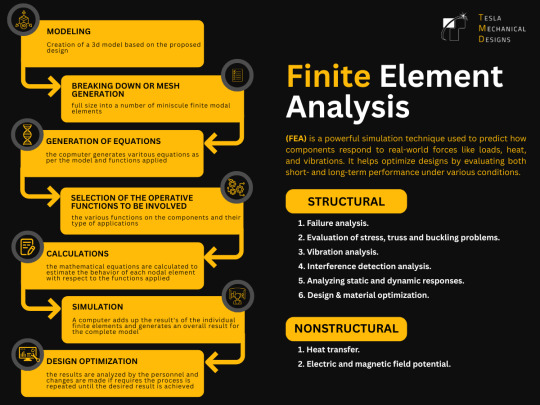
Finite Element Analysis (FEA) is a vital tool in product development, allowing engineers to simulate and evaluate real-world conditions—such as stress, heat, vibration, and load—before a single prototype is built.
Our latest infographic provides a clear and concise overview of the FEA process, including:
✔️ Key stages of FEA: from model creation to post-processing ✔️ Applications across structural, thermal, and fatigue analysis ✔️ Advantages such as improved design efficiency, reduced costs, and risk mitigation
Whether you're developing complex mechanical systems or refining a single component, FEA is essential for informed decision-making and performance optimization.
📈 View the full infographic and learn more: 🔗 Finite Element Analysis
#Engineering#FiniteElementAnalysis#MechanicalDesign#Simulation#ProductDevelopment#TeslaMechanicalDesigns
0 notes
Text
Proven Performance of PVC Pipe in
The Uni-Bell PVC Pipe Association has completed a comprehensive two-part research initiative to evaluate the long-term performance of PVC sewer pipe in deep-bury conditions.
The first component used finite element analysis (FEA) to simulate how PVC pipe behaves under various soil and loading conditions. This modeling provided a detailed view of the expected structural response in deep installations.
The second component applied laser profiling technology to an in-service PVC sewer interceptor that has been operating for over 45 years, installed at depths reaching 28 feet. This method offered high-resolution data on the actual deflection and shape of the buried pipe.
FEA modeling answered the question, “What should it look like?” while laser profiling addressed “What does it look like?” The results from both analyses aligned closely, confirming that PVC pipe performs exceptionally well under deep-bury conditions with minimal deflection or structural degradation.
This dual-approach research provides strong evidence of PVC’s reliability and durability in demanding gravity sewer applications.
For detailed findings, read the full report: PVC Pipe in Deep-Bury Applications: FEA Modeling and Field Inspection of PVC Sewer Pipe.
0 notes
Text
Key Design Features Planetary Gearbox Manufacturers Focus On
Planetary gearboxes are integral to a wide range of industrial applications due to their high efficiency, compact design, and excellent torque density. Behind their apparent simplicity lies a highly engineered system that demands meticulous attention to detail. Planetary gearbox manufacturers focus on several key design features to ensure these gear units deliver optimal performance, durability, and reliability across varying load conditions and industries.
Let’s explore the major design aspects manufacturers prioritize to craft gearboxes that stand the test of time and performance.

Engineering Precision Behind Every Planetary Gearbox
Planetary gearboxes are more than just a collection of gears in a housing—they represent a synergy of mechanical engineering, material science, and advanced manufacturing techniques. The core design principles revolve around maximizing torque output, minimizing size, reducing heat buildup, and ensuring smooth and reliable transmission over long operational cycles.
Gear Arrangement and Load Sharing Geometry
One of the primary design features of a planetary gearbox is the epicyclic arrangement of gears. This includes a central sun gear, multiple planet gears, and an outer ring gear. This configuration enables uniform load distribution across all planet gears, ensuring balanced stress and reduced gear wear. Manufacturers pay careful attention to gear spacing and symmetry to maintain even load sharing, which enhances the gearbox’s lifespan and operational stability.
High Torque Density Through Compact Architecture
Compactness without compromising power is a hallmark of planetary gearboxes. Manufacturers optimize the design to deliver high torque density—that is, maximum torque in the smallest possible footprint. This is achieved by efficiently using the planetary configuration to multiply torque, making these gearboxes ideal for space-constrained and high-load applications such as robotics, automotive systems, and heavy-duty machinery.
Gear Tooth Profile Optimisation
Another crucial design focus is the gear tooth profile. Planetary gearbox manufacturers leverage advanced software tools and machining technologies to craft tooth profiles that ensure smooth meshing, minimal friction, and noise reduction. Involute profiles are commonly used, but even within this standard, tweaks in pressure angles, helix angles, and contact ratios can significantly impact performance. Proper tooth geometry reduces backlash and enhances efficiency.
Bearing and Shaft Alignment
Bearings and shafts form the backbone of the gear transmission system. Misalignments can cause uneven wear, vibration, and premature failure. Top manufacturers use precision engineering and quality bearing systems to ensure perfect shaft alignment and support. This helps maintain consistent meshing of gear teeth, enhances load handling capabilities, and improves the overall mechanical efficiency of the gearbox.
Housing and Structural Integrity
The gearbox housing isn’t just a container—it provides the structure and alignment for the internal components. Manufacturers focus on creating rigid, vibration-resistant housings that can withstand mechanical loads and environmental stress. Finite Element Analysis (FEA) is often used during the design stage to evaluate stress distribution and structural integrity. A well-designed housing helps in minimizing noise, supporting thermal management, and ensuring long-term durability.
Material Selection as a Design Variable
Material choice significantly influences the strength, weight, and thermal properties of a planetary gearbox. Manufacturers often use alloy steels, hardened materials, and specialized surface treatments for gears and shafts to enhance wear resistance and load capacity. Housing materials may include cast iron, aluminum, or steel depending on the application. The right combination of materials not only improves performance but also optimizes the cost-to-durability ratio.
Thermal Management by Design
Thermal buildup due to friction and load is a major concern in gearbox operation. Overheating can degrade lubrication and lead to component failure. Manufacturers address this by designing for efficient thermal dissipation—using cooling fins, high-grade lubricants, and strategic material selection. Some designs also incorporate integrated cooling systems or allow for the addition of external cooling units in heavy-duty applications.
Gearbox Mounting and Alignment Precision
Proper mounting and alignment are critical to gearbox performance. Misalignment can lead to shaft deflection, increased wear, and noise. Manufacturers ensure that their gearboxes are designed with precise mounting surfaces, alignment guides, and dowel pin arrangements. These features help in easy and accurate installation, reducing setup time and eliminating common causes of misalignment-related failures.
Modular Design Philosophy
Modern planetary gearbox manufacturers are increasingly embracing a modular design approach. This allows for customization and flexibility without the need for complete redesigns. Modular designs offer interchangeable components such as gear stages, mounting flanges, and input/output options, enabling easier integration into various industrial systems. They also simplify maintenance and allow for scalability in performance.
Partner with Santram Engineers for Design-Driven Industrial Gearbox Solutions
With over three decades of experience in power transmission solutions, Santram Engineers stands at the forefront of design innovation and precision manufacturing. We understand that every industrial application comes with unique challenges. That’s why we focus on delivering custom-engineered planetary gearboxes that incorporate the latest in material science, gear design, and assembly technology.
From precision bearing systems to modular builds, every gearbox we deliver is a result of meticulous design planning and rigorous quality control. Whether you’re in material handling, automation, mining, or marine applications, Santram Engineers offers the reliability, performance, and service support you need to keep operations running smoothly.
Why Choose Santram Engineers?
Design Precision: Our team uses the latest CAD and FEA tools to ensure each gearbox is optimized for strength, performance, and longevity.
Material Expertise: We select materials based on detailed analysis of the application environment, ensuring best-in-class wear resistance and thermal stability.
End-to-End Support: From design consultation to after-sales service, we’re with you at every stage.
Customization: Need a non-standard input, output, or mounting option? Our modular designs make it easy to adapt gearboxes to your system.
Quality Assurance: Rigorous testing protocols guarantee that each unit meets performance benchmarks before delivery.
Conclusion
The performance of a planetary gearbox depends not just on the number of gears it contains but on how thoughtfully each design element is engineered. From gear arrangement to material selection, and from thermal management to modularity, every aspect plays a critical role in delivering efficient and durable power transmission.
If you're seeking a gearbox partner that prioritizes performance through design, Santram Engineers is your trusted source for reliable and customized gearbox solutions.
Visit us at: https://www.santramengineers.com/key-design-features-planetary-gearbox-manufacturers/ Explore how our design-driven approach can elevate your industrial systems.
0 notes
Text
The Unsung Hero Behind Safe Pipelines: Stress Analysis in Industrial Engineering
In the evolving world of industrial infrastructure, Piping Stress Analysis has emerged as a foundational element in ensuring system safety, efficiency, and longevity. From oil refineries to HVAC installations, accurately understanding how pipes respond to operational forces is not just a technical requirement—it’s a safety imperative. At the heart of this process stands the Stress Analysis Engineer, a professional whose expertise prevents disasters before they happen.
Understanding the Core: What is Piping Stress Analysis?
Piping Stress Analysis involves a detailed evaluation of pipe systems to determine whether they can endure real-world pressures—including internal fluid dynamics, temperature shifts, mechanical forces, and external loads—without damage or failure. Engineers use this analysis to assess critical issues like:
Thermal expansion
Mechanical vibration
Deadweight and dynamic forces
Without proper analysis, the consequences can be severe: from minor leaks to catastrophic pipeline failures. Therefore, industries must adhere to international safety standards like ASME B31.1, B31.3, ISO, and ANSI.
Why Modern Industries Can’t Ignore Stress Analysis
Prevents Structural Failures It minimizes the chances of leaks, cracks, or bursts due to stress overload.
Ensures Legal Compliance Meets rigorous safety and regulatory benchmarks across global industries.
Optimizes Long-Term Costs Avoids frequent repairs or unplanned downtimes.
Improves Operational Reliability Keeps pipelines running without interruption, ensuring productivity.
Supports Smarter Design Guides engineers to develop efficient layouts using minimal materials while ensuring durability.
The Specialist in Action: What Does a Stress Analysis Engineer Do?
A Stress Analysis Engineer is tasked with analyzing piping systems to predict their behavior under operating and fault conditions. Using a blend of technical knowledge, software tools, and code compliance, they help avert costly and hazardous issues.
Typical Responsibilities Include:
Using specialized tools like CAESAR II, ROHR2, and AutoPIPE to simulate stress conditions
Designing proper support systems (anchors, hangers, expansion joints)
Advising layout adjustments for better stress distribution
Documenting compliance with engineering standards and codes
Evaluating responses to environmental forces like earthquakes or wind
Skills That Define an Effective Stress Analyst
To succeed in this specialized role, engineers require:
Mastery in stress analysis platforms
Deep understanding of materials, thermal dynamics, and fluid mechanics
Strong command of piping design codes (e.g., ASME, ANSI)
Analytical and decision-making capabilities
Clear communication for cross-team collaboration
Industries Where Stress Analysis is Vital
Oil & Gas High-pressure systems in offshore and onshore drilling demand constant analysis to ensure integrity.
Power Plants Steam and gas lines undergo extreme thermal fluctuations—precision stress handling is key.
Chemical and Petrochemical Plants Aggressive chemicals and varying conditions make these systems vulnerable to stress-related wear.
Pharmaceutical and Food Facilities Sterile and pressurized environments require robust, compliant piping systems.
Commercial HVAC Building-scale heating and cooling systems benefit from stress assessment to avoid premature wear.
Tools Empowering Today’s Stress Engineers
Stress engineers use cutting-edge technology to simulate physical realities and predict outcomes:
CAESAR II – Industry leader in pipe stress analysis
AutoPIPE – Comprehensive tool for piping and structural evaluations
ROHR2 – Widely adopted in European markets
ANSYS – Ideal for advanced Finite Element Analysis (FEA)
SolidWorks Simulation – Assists in preliminary design stress testing
Real-World Engineering Challenges in Stress Analysis
Thermal Effects: Expanding or contracting pipes due to temperature swings
Mechanical Vibrations: Equipment-induced stress from pumps and turbines
Improper Support Design: Misplaced supports lead to uneven load distribution
Dynamic Forces: Shock loads from seismic activity or fluid surges (water hammer)
Charting the Path: Becoming a Stress Analysis Engineer
Want to build a career in this critical domain? Here's a simple roadmap:
Get a Mechanical Engineering Degree
Train in Specialized Software Tools (like CAESAR II, AutoPIPE)
Secure Relevant Certifications (e.g., piping code standards)
Build Experience in industrial environments under senior professionals
Stay Updated on technology, standards, and simulation methodologies
What’s Next? Trends Shaping the Future
BIM Integration: Seamless collaboration through Building Information Modeling
AI-Driven Simulations: Using machine learning to predict risk zones
Cloud-Based Analysis: Enabling remote and collaborative project execution
Eco-Conscious Design: Focus on green engineering and sustainable materials
Final Thoughts: The Backbone of Infrastructure Safety
A well-executed Piping Stress Analysis doesn't just ensure operational efficiency—it protects lives, investments, and the environment. And it is the Stress Analysis Engineer, with their sharp insights and tools, who ensures our pipelines remain strong and safe.
0 notes
Text
Teamwork in Action: Mechanical Engineering in Aerospace Projects
In the high-stakes world of aerospace engineering, where precision, safety, and innovation are paramount, mechanical engineers don’t work in silos. Their success depends on a tightly integrated network of professionals collaborating at every stage—from concept and simulation to final assembly and testing. This article explores how teamwork drives mechanical engineering success in complex aerospace projects.
1. A Shared Mission: Precision and Performance
Aerospace projects typically begin with a clear objective: to build systems that are lightweight, Intellectual Property Expert Witness strong, efficient, and capable of withstanding extreme conditions. Whether the task is designing a new satellite component or enhancing jet propulsion, mechanical engineers work alongside systems engineers, materials scientists, and aerodynamics experts to ensure every requirement is met.
At the heart of every successful project is a shared mission—safety, reliability, and performance in flight. That mission unites teams and guides every decision.
2. Concept Development: Multi-Disciplinary Brainstorming
In the early design stages, collaboration is critical. Mechanical engineers contribute core knowledge of structural mechanics, heat transfer, and mechanical systems. At the same time, electrical engineers bring insight into avionics and control systems, while software teams prepare algorithms for navigation and guidance.
By working together from day one, the team ensures the system is well-integrated and that mechanical design decisions support overall functionality.
3. Advanced Design: CAD, Simulation, and Analysis
Once initial concepts are approved, the mechanical design team, along with CAD specialists, begins creating detailed models of components—ranging from turbine blades to landing gear systems.
Simultaneously, analysts run Finite Element Analysis (FEA) and Computational Fluid Dynamics (CFD) simulations. This stage exemplifies deep teamwork: designers must coordinate with simulation teams to iterate quickly, adjusting dimensions and materials based on performance feedback.
This real-time collaboration between designers and analysts accelerates development and minimizes the risk of failure in later stages.
4. Material Science and Manufacturing Input
Aerospace components must endure high stress, rapid temperature changes, and corrosive environments. That’s where materials engineers step in. They recommend lightweight alloys, carbon fiber composites, and coatings that enhance performance without adding unnecessary mass.
Working closely with mechanical engineers, the materials team ensures that selected components meet both mechanical and environmental requirements.
Additionally, manufacturing engineers collaborate during this phase to ensure that parts can be machined or fabricated with the precision demanded by aerospace standards.

5. Integration and Systems Engineering
Mechanical systems in aerospace projects rarely function alone. They interact with hydraulic, electrical, and software systems. Integration engineers manage this complexity, coordinating all teams to ensure seamless interaction between subsystems.
Mechanical engineers must constantly align their work with these integration goals—making adjustments to fit within system constraints or improve compatibility with avionics and onboard diagnostics.
This integration phase demands constant communication, version control, and detailed documentation.
6. Testing, Validation, and Quality Assurance
Once a prototype is built, the testing phase begins. Teams of engineers, technicians, and quality specialists collaborate to put the system through rigorous evaluations, including stress testing, thermal cycling, and vibration testing.
Mechanical engineers interpret results and work with analysts and designers to make improvements. Every issue found becomes a team challenge to solve—quickly and effectively.
This phase reinforces the idea that aerospace success is built on collective problem-solving, not individual achievement.
7. Flight-Ready: Final Assembly and Launch Support
The final step involves integrating all components into the complete aerospace system, whether it’s a commercial aircraft, space probe, or defense satellite. Here, collaboration extends to logistics teams, suppliers, and assembly technicians.
Mechanical engineers support final checks and provide technical guidance on-site during installation and launch preparation. This end-to-end involvement showcases how every team member's input contributes to a successful mission.
Conclusion
Teamwork isn’t just helpful in aerospace mechanical engineering—it’s essential. From concept to launch, success is driven by collaboration across disciplines. Whether it’s choosing the right material, refining a component, or solving a critical systems issue, the combined effort of a cross-functional team ensures that aerospace projects fly high—literally and figuratively.
0 notes
Text
Unlocking Engineering Precision with FEA and CAD Integration
In today’s fast-paced and innovation-driven engineering environment, the ability to model, analyze, and validate designs before physical production is not just an advantage—it’s a necessity. This is where the integration of Computer-Aided Design (CAD) and Finite Element Analysis (FEA) becomes a game-changer. Together, these technologies provide engineers with the tools to optimize product designs, reduce development time, and minimize costs while ensuring product quality and reliability.
What is CAD?
Computer-Aided Design (CAD) refers to the use of computer software to create precise drawings, technical illustrations, and 3D models of products or parts. CAD software has become an indispensable tool in industries such as automotive, aerospace, electronics, and consumer goods, where design precision and visualization are critical.
CAD tools allow engineers and designers to:
Create 2D and 3D representations of products.
Modify and iterate designs with ease.
Visualize complex components before physical prototyping.
Integrate with manufacturing systems like CAM (Computer-Aided Manufacturing) for seamless production workflows.
What is FEA?
Finite Element Analysis (FEA) is a numerical method used to simulate and analyze physical phenomena such as structural stress, thermal performance, vibration, and fluid dynamics. By breaking down complex geometries into smaller, manageable elements (the "finite elements"), FEA allows for the detailed evaluation of how a product will perform under real-world conditions.
Engineers use FEA to:
Predict potential design failures before production.
Understand stress concentrations and material behavior.
Test various loading conditions and environmental factors.
Optimize designs for strength, weight, and performance.
The Power of CAD and FEA Integration
While CAD is primarily focused on designing the geometry and structure of a part or system, FEA provides insight into how that part will behave under various operational conditions. Integrating CAD and FEA creates a cohesive workflow that empowers engineers to design with performance in mind from the start.
Here are some key benefits of this integration:
1. Faster Design Cycles
The seamless flow of information from CAD models into FEA simulations eliminates the need to recreate geometry or manually input data. Design changes can be made in CAD and instantly updated in FEA, reducing time spent on repetitive tasks and speeding up design iterations.
2. Enhanced Design Accuracy
CAD models offer exact geometric representations, which are essential for reliable simulation in FEA. Using accurate CAD models in FEA ensures that the analysis reflects true product geometry, improving the validity of the results.
3. Cost Reduction
Identifying design flaws or inefficiencies early in the development cycle means fewer physical prototypes, less rework, and reduced material waste. This significantly lowers development costs and shortens time-to-market.
4. Optimized Performance
By using FEA within the CAD environment, engineers can simulate how designs respond to different forces and conditions. This allows for iterative optimization—adjusting shape, material, or thickness to achieve peak performance while minimizing weight and material usage.
5. Streamlined Collaboration
CAD/FEA integration fosters collaboration among engineering teams. Designers and analysts can work from a single model, share insights more effectively, and maintain version control throughout the product development process.
Real-World Applications
The CAD-FEA combination is transforming design processes across multiple industries:
Automotive: Simulating crash tests, heat dissipation in engines, and durability of suspension systems.
Aerospace: Ensuring structural integrity under extreme pressure and temperature conditions.
Medical Devices: Evaluating the strength and performance of implants and surgical tools.
Consumer Electronics: Assessing thermal performance of devices to prevent overheating.
Choosing the Right Tools
There are several CAD and FEA software platforms that offer strong integration, including:
SolidWorks + SolidWorks Simulation: A popular option for mechanical engineers, allowing integrated design and analysis.
Autodesk Inventor + Nastran: Offers a powerful suite for simulation and mechanical design.
PTC Creo + Creo Simulate: Known for high-fidelity simulation with real-time feedback during the design process.
Siemens NX: An advanced solution that tightly couples CAD and simulation for complex product development.
Best Practices for CAD/FEA Integration
Design for Analysis: When creating CAD models, think ahead to the FEA phase. Avoid overly complex geometry and ensure features like fillets and holes are appropriately represented.
Validate Mesh Quality: A proper mesh ensures simulation accuracy. Pay attention to mesh refinement in areas of high stress or geometric complexity.
Material Properties: Use accurate material data in your simulations. Many FEA tools include built-in libraries, but real-world testing or manufacturer data is often best.
Boundary Conditions: Realistic loading, constraints, and environmental conditions are key to getting valuable simulation results.
Iterative Process: Use FEA results to refine your CAD model. Small changes can lead to big improvements in performance and cost-efficiency.
The Future of CAD and FEA
As technologies like AI, machine learning, and cloud computing continue to evolve, CAD and FEA integration is becoming even more powerful. Generative design, where software automatically proposes optimal shapes based on performance requirements, is already pushing boundaries. Cloud-based platforms now allow for high-performance simulations without investing in expensive hardware.
Conclusion
The combination of CAD and FEA by Servotechinc empowers engineers to create better, smarter products in less time. By simulating real-world performance during the design phase, companies can deliver safer, more efficient, and more innovative solutions to market faster and more affordably.
Whether you're designing the next electric vehicle, a surgical implant, or a high-rise building component, integrating FEA into your CAD workflow gives you the insight and precision to engineer with confidence.
0 notes
Text
Servotech FEA Services for Smarter Engineering
In today’s competitive engineering landscape, staying ahead means designing smarter, safer, and more efficient products—faster than ever before. Servotech, a leader in simulation and digital engineering, delivers top-tier Finite Element Analysis (FEA) services to empower engineers, manufacturers, and innovators to make better design decisions early in the product development cycle. With cutting-edge tools and a deep understanding of structural mechanics, Servotech is revolutionizing how companies approach complex engineering challenges.
What is FEA and Why It Matters
Finite Element Analysis (FEA) is a computer-based simulation technique used to predict how products will react to real-world forces like heat, vibration, stress, and motion. By creating a virtual model and breaking it down into small finite elements, engineers can evaluate structural performance and identify weak points without the cost or time of building physical prototypes.
FEA plays a critical role in industries such as:
Automotive and aerospace
Electronics and consumer products
Energy and utilities
Heavy machinery and industrial equipment
Biomedical and healthcare devices
For companies seeking reliability, safety, and regulatory compliance, FEA is not just a tool—it’s an essential part of modern engineering.
Why Choose Servotech for FEA?
Servotech brings more than just simulation software to the table. Their FEA services combine technical precision, industry experience, and engineering intelligence to deliver results that matter.
1. Expertise Across Multiple Domains
Servotech’s team of certified FEA engineers have experience across mechanical, thermal, structural, and dynamic analysis. Whether it's crash simulation for an automobile or thermal stress in electronics, Servotech delivers multi-physics solutions that integrate seamlessly into your workflow.
2. Customized Simulation Solutions
No two projects are the same. Servotech tailors its FEA services to meet the unique demands of your product, industry, and design constraints. From linear static analysis to non-linear and dynamic simulations, the team adapts the modeling techniques and software tools to provide actionable insights specific to your needs.
3. Advanced Software Capabilities
Servotech utilizes industry-standard FEA software tools such as:
ANSYS
Abaqus
HyperMesh
SolidWorks Simulation
COMSOL Multiphysics
These tools allow them to offer high-fidelity simulation, mesh optimization, and fast computation, resulting in more accurate and reliable predictions.
4. Focus on Design Optimization
FEA isn’t just about identifying problems—it’s about solving them. Servotech’s engineers work collaboratively with your design team to recommend geometry improvements, material selection, and load optimization strategies that enhance performance while minimizing cost and weight.
5. Accelerated Time to Market
By integrating FEA early in the product development lifecycle, Servotech helps clients reduce prototyping cycles, prevent late-stage design changes, and accelerate time to market. This early detection of issues leads to significant cost savings and improved product reliability.
Key FEA Services Offered by Servotech
Structural Analysis
This includes static, dynamic, and non-linear stress analysis for components and assemblies. Servotech helps clients determine deformation, fatigue, failure risk, and load distribution across materials and structures.
Thermal Analysis
Heat management is crucial, especially in electronics, automotive, and aerospace applications. Servotech performs steady-state and transient thermal analysis to understand how temperature affects structural integrity and material behavior.
Modal and Vibration Analysis
Servotech simulates natural frequencies, mode shapes, and harmonic response to evaluate how components behave under dynamic loading. This is vital for rotating machinery, engines, and structural components prone to vibration.
Buckling and Stability
For slender structures under compressive loads, Servotech conducts buckling analysis to determine critical loads and ensure structural stability in columns, panels, and frameworks.
Fatigue and Lifecycle Prediction
Using industry-standard fatigue models, Servotech estimates product lifespan under cyclic loading and recommends design modifications to enhance durability and longevity.
Multi-Physics Simulations
Combining FEA with other domains like CFD (Computational Fluid Dynamics) and electromagnetics, Servotech performs multi-physics analysis for advanced applications such as battery systems, thermal-fluid systems, and smart electronics.
Industries Benefiting from Servotech’s FEA Expertise
Automotive
From chassis design to crashworthiness analysis, Servotech assists automotive OEMs and suppliers in designing vehicles that are lighter, safer, and more efficient.
Aerospace
In a field where weight optimization and safety are paramount, Servotech offers structural, thermal, and vibration analysis for aircraft components and space systems.
Consumer Electronics
With the miniaturization of electronics, thermal and structural integrity becomes critical. Servotech helps design heat-resistant and robust enclosures, PCBs, and connectors.
Medical Devices
For surgical tools, implants, and diagnostic equipment, Servotech ensures mechanical safety and regulatory compliance through simulation-backed development.
Energy and Utilities
Whether it's stress testing of wind turbine blades or thermal analysis of power distribution systems, Servotech supports the renewable and conventional energy sectors in designing more reliable systems.
The Servotech Advantage: Smarter Engineering, Delivered
Choosing Servotech means you’re not just outsourcing a simulation—you’re gaining a partner who understands the end goal: better performance, lower costs, and faster innovation. Their collaborative approach ensures that simulation insights directly inform design improvements and product strategy.
Key differentiators include:
In-house expertise and fast turnaround
Cross-disciplinary engineering support
Proven track record across diverse industries
Confidential, secure handling of proprietary data
Transparent reporting and clear interpretation of simulation results
Client Success Stories
Case Study 1: Automotive Suspension Design Servotech helped a leading auto parts supplier reduce component weight by 15% without compromising safety by using dynamic and fatigue FEA to optimize geometry and material.
Case Study 2: Medical Device Durability A medical device startup collaborated with Servotech to validate a new surgical tool design. Using non-linear FEA, Servotech identified potential fracture points, allowing the client to redesign for longer lifespan and pass FDA testing faster.
Conclusion
In a world driven by innovation and efficiency, Servotech’s FEA services are redefining what’s possible in engineering. By integrating high-fidelity simulation with engineering know-how, they help businesses transform bold ideas into high-performance products.
0 notes
Text
Unveiling the Strength: A Comprehensive Finite Element Analysis of the Strap U-Frame

In the realm of engineering, structural integrity and performance are paramount. At Graphler Technology Solutions, our commitment to delivering cutting-edge analyses ensures that every project achieves its full potential. Recently, we undertook an extensive finite element analysis (FEA) of a Strap U-Frame. This blog delves into the highlights and insights from the study.
Objective of the Study:
The primary goal of the FEA was to evaluate the structural behavior of the Strap U-Frame under a variety of operational loads and conditions. This included assessing how the U-Frame responded to forces induced by tension in the strap, moments generated during operation, and reaction forces from components like the crank and pawl. By simulating these real-world conditions, the analysis aimed to:
Identify Critical Stress Points: Determine locations within the U-Frame where stress exceeded safe operational thresholds, particularly areas prone to potential cracking or fatigue failure.
Examine Deformation Patterns: Evaluate how the structure deforms under load to ensure that any displacements remain within acceptable limits to maintain functionality.
Validate Material Performance: Analyze whether the materials selected for the U-Frame and its components could withstand the applied loads without permanent damage or failure.
Guide Design Improvements: Provide actionable insights for optimizing the design and material usage to enhance durability, safety, and cost-effectiveness.
This holistic approach ensured that the U-Frame design met stringent performance standards while aligning with the operational demands and longevity expectations of the client.
Analysis Setup
The analysis focused on multiple load cases, including:
Belt Tension: Simulated at 26688 N, generating a significant moment of 1334400 N-mm.
Force Transmission: Evaluated through the crank lever requiring a force of 3587.10 N for operation.
Boundary conditions, material properties, and operational loads were meticulously configured to replicate real-world scenarios.
Key Findings
1. Deformation Analysis
Maximum deformation observed: 2.93 mm.
Despite localized deformation, the overall structure maintained functional integrity.
2. Stress Distribution
U-Frame: Maximum principal stress reached 1032 MPa, exceeding the material’s ultimate tensile strength. However, the stress concentration was confined to the surface peel layer, indicating potential for localized cracking without immediate failure.
Pawl: Maximum stress of 858.23 MPa surpassed yield strength at contact points. The compressive nature of stress ensured no catastrophic failure.
Shaft: Surface stress exceeded yield strength but remained within acceptable limits at the core, highlighting resilience against major deformation or breakage.
3. Reaction Forces

4. Engineering Inferences
Localized Cracking: Stress concentrations in the U-Frame and Pawl necessitate enhanced surface treatments or reinforcements to mitigate fatigue risks.
Material Performance: While the materials demonstrated high resilience, exceeding yield thresholds in localized regions requires design refinements.
Optimized Design: Potential adjustments in geometry or material distribution can enhance load-bearing capacity without significant weight increases.
Graphler Technology is one of the leading product design companies in India. We have experts in FEA services and also we are specialized in CFD consulting services, structural design services, 2D to 3D Conversion services, stress analysis services etc.
0 notes
Text
Unlock the Full Potential of Engineering Simulation with Femap
In today’s highly competitive manufacturing and engineering landscape, simulation-driven design is not just an advantage — it’s a necessity. Engineers and analysts need robust tools that offer high performance, accuracy, and flexibility without unnecessary complexity or cost. This is where Femap, a Siemens Digital Industries Software product, steps in. As a standalone finite element analysis (FEA) pre- and post-processor, Femap empowers engineers to model, simulate, and visualize complex engineering systems.
What is Femap?
Femap is an advanced engineering simulation tool used to build finite element models of complex products or systems and to evaluate them under real-world conditions. It works seamlessly with NX Nastran or other solvers, enabling users to conduct detailed structural, thermal, and dynamic simulations. This makes Femap a vital solution for CAE professionals who require deep insights into product performance — before any physical prototype is built.
Key Features
Integrated pre- and post-processor
CAD-independent geometry import and clean-up
Advanced meshing and geometry editing tools
Linear and nonlinear simulation capabilities
Fatigue, vibration, and thermal analysis
Solver-neutral architecture
Custom automation using APIs
Easy model comparison and error checking
Benefits of Using Femap
✅ Accelerate Product Development: Perform virtual tests early and reduce dependency on physical prototypes.
✅ Reduce Costs: Lower material waste and redesign efforts with more accurate simulation.
✅ Improve Product Reliability: Identify stress points and failure modes before manufacturing.
✅ Enhance Collaboration: Share detailed simulation insights across teams and stakeholders.
✅ Boost Innovation: Simulate complex scenarios and explore design alternatives with ease.
✅ Easy Integration: Works with popular CAD systems and various solvers, making implementation seamless.
Why DDSPLM for Femap?
Choosing the right technology partner is just as critical as choosing the right software. DDSPLM is a trusted Siemens Digital Industries Software partner with years of domain expertise in PLM, CAD, and simulation technologies. Here’s why customers choose DDSPLM for Femap:
✔️ Certified Siemens Solution Partner
✔️ Expert Consultation & Implementation Support
✔️ Industry-Specific Customization
✔️ Ongoing Training & Technical Assistance
✔️ Strong Post-Sales Service & Maintenance
✔️ Experience Across Automotive, Aerospace, Electronics & More
If you’re looking to advance your simulation capabilities with a powerful, reliable, and cost-effective tool, Femap is the solution of choice. And when partnered with DDSPLM, you get more than just software — you gain a long-term technology partner committed to your success.

0 notes
Text
How to Choose the Best ERP for Small Business: A Complete Buyer’s Guide
Selecting the best ERP for small business can feel like an overwhelming task with the numerous options available today. An ERP (Enterprise Resource Planning) system is critical for streamlining business operations, improving efficiency, and providing insights for smarter decision-making. For small businesses, it’s essential to choose an ERP solution that aligns with specific needs without breaking the budget.
This comprehensive buyer’s guide will walk you through the key considerations to make when selecting an ERP system for your small business. Whether you're looking to manage inventory, track finances, or expand your operations, understanding the core features and benefits of different ERP solutions will ensure you make an informed decision. Additionally, we will explore the advantages of cloud ERP for small businesses, helping you understand why it might be the ideal solution.
What is an ERP System, and Why Do Small Businesses Need One?
An ERP system is a suite of integrated applications that automate and manage business processes such as accounting, inventory management, sales, human resources, and procurement. For small businesses, implementing an ERP system is a game-changer, as it helps to streamline operations, reduce errors, and provide real-time data for better decision-making.
Key Benefits of ERP for Small Business
Improved Efficiency: With automated processes, tasks that would otherwise require manual effort are handled by the ERP system, saving time and reducing human error.
Cost Savings: ERP systems reduce the need for multiple software solutions, which can be costly and difficult to manage.
Data-Driven Insights: Access to real-time data helps small business owners make informed decisions, anticipate market trends, and improve customer satisfaction.
Scalability: As your business grows, an ERP system can scale with you, adapting to your evolving needs.
Now, let’s explore the critical factors to consider when choosing the best ERP for small business.
1. Understand Your Business Needs
Before diving into the different ERP solutions, it’s essential to understand what your business needs. Not all ERPs are created equal, and some may offer features that are unnecessary for your business. To make the right choice, take a step back and assess your current business processes.
Consider the following questions:
What departments or functions need to be integrated (finance, HR, inventory, etc.)?
Are you looking for a system to support e-commerce or multi-location operations?
Do you need industry-specific features (e.g., for manufacturing or retail)?
Will your business need the flexibility to scale in the near future?
Understanding these requirements will help you narrow down your options and focus on ERPs that are best suited for your business needs.
2. Evaluate Core Features of the Best ERP for Small Business
A small business ERP system must have several core features to ensure it can handle day-to-day operations efficiently. Here are the must-have features to look for:
a. Inventory Management
If your business deals with physical products, efficient inventory management is crucial. Look for ERPs with robust features for tracking stock levels, managing reorders, and maintaining accurate inventory data.
b. Financial Management
One of the main reasons small businesses invest in an ERP system is to streamline financial management. The best ERP for small business should offer features like accounts payable and receivable, budgeting, financial reporting, and tax compliance.
c. Customer Relationship Management (CRM)
A CRM feature helps you track customer interactions, manage leads, and improve customer satisfaction. Many modern ERP systems come with built-in CRM tools or integrate seamlessly with third-party CRMs.
d. Human Resource Management
Managing employee records, payroll, benefits, and performance is vital for small businesses. An ERP that includes HR features can save time and effort in handling these processes.
e. Reporting and Analytics
Access to real-time, customizable reports is crucial for informed decision-making. Choose an ERP system that allows you to track KPIs, generate financial reports, and analyze data across various business functions.
3. Cloud ERP for Small Businesses: Why It’s the Future
One of the biggest trends in ERP software today is the adoption of cloud ERP for small businesses. A cloud-based ERP system can offer significant advantages over traditional on-premise solutions, especially for small businesses.
Benefits of Cloud ERP:
Lower Upfront Costs: Cloud-based ERPs are subscription-based, meaning you don’t need to invest in expensive hardware or software licenses upfront.
Accessibility: With cloud ERP, your data and applications are accessible from anywhere, as long as you have an internet connection. This is particularly beneficial for businesses with remote teams or multiple locations.
Automatic Updates: Cloud ERP providers handle system updates, ensuring you always have access to the latest features and security patches without manual intervention.
Scalability: Cloud ERPs grow with your business. You can easily add more users or features as your needs evolve.
Given these benefits, cloud ERP for small businesses is often the best choice for small business owners looking to implement a scalable, cost-effective solution.
4. Compare Vendors and Pricing
Once you have a clear understanding of your needs and the features you’re looking for, it’s time to evaluate different ERP vendors. Here are some tips for comparing ERP systems:
a. Vendor Reputation
Research each vendor’s reputation by reading customer reviews and case studies. Look for testimonials from businesses similar to yours to gauge the effectiveness of the system.
b. Pricing Transparency
Ensure the ERP vendor provides clear, upfront pricing. Be wary of hidden costs or long-term contracts. Compare subscription fees, customization costs, and support fees to determine the true total cost of ownership.
c. Customer Support
Good customer support is vital when implementing an ERP system. Make sure the vendor offers 24/7 support or assistance during your business hours. Ideally, the vendor should provide training and onboarding resources to help your team get up to speed quickly.
5. Ensure Scalability and Flexibility
The best ERP for small business is one that can scale as your business grows. You may need more users, additional features, or integration with other tools as your business expands. A flexible ERP solution will allow you to add functionality or upgrade your system without major disruptions.
Look for ERPs that offer:
Modular options for adding features as needed
Easy integration with third-party software (e.g., e-commerce platforms or CRM systems)
Cloud solutions that allow for simple scalability
6. Calculate the ROI of Your ERP System
Before finalizing your ERP decision, it’s essential to evaluate the potential return on investment (ROI). While ERPs come with an initial cost, they can deliver significant benefits over time, including increased efficiency, cost savings, and better decision-making.
To calculate the ROI of your ERP system, consider the following:
Time Savings: How much time will your team save by automating manual processes?
Cost Reductions: Will the ERP system help reduce operational costs (e.g., inventory management, accounting errors)?
Increased Revenue: Can the ERP help you increase sales or improve customer satisfaction, leading to more business?
7. Take Advantage of Free Trials
Many ERP vendors offer free trials or demo versions of their software. Taking advantage of these trials is a great way to evaluate the system’s user interface, functionality, and ease of use before committing to a long-term contract.
Conclusion
Choosing the best ERP for small business is a significant decision that will impact your operations for years to come. By understanding your business needs, evaluating core features, and exploring the benefits of cloud ERP for small businesses, you can select the right ERP system to streamline your processes, improve efficiency, and scale as your business grows.
Remember, the ideal ERP solution will depend on your unique requirements, and it’s important to take your time during the decision-making process. At Intelegain Technologies, we provide comprehensive ERP solutions tailored to your business needs. Whether you’re looking for cloud-based ERP or a customized solution, we can help you find the perfect fit. Contact us today to learn how our ERP solutions can drive your business forward.
0 notes