#International Rectifier MOSFET
Explore tagged Tumblr posts
Visit Tumblr Blog
Explore Tumblr blogs with no restrictions, modern design and the best experience.
Last Seen Tumblr Blogs


Fun Fact
Tumblr was named as a finalist in Lead411’s New York City Hot 125 in Aug 2010.
Text
Boost Efficiency with the IRPT1058A MOSFET Module
Take your power electronics projects to the next level with the IRPT1058A MOSFET module, available for global delivery. Visit https://www.uscomponent.com/buy/International_Rectifier/IRPT1058A today to learn more or place your order.
For industries demanding high performance and reliability, the IRPT1058A MOSFET module from the International Rectifier (IR) stands out as a top-tier solution for efficient power management. Combining exceptional switching performance with robust durability, this power module is perfect for motor drives, power supplies, industrial automation, and renewable energy systems applications.
Designed to handle high voltage and current loads with minimal power loss, the IRPT1058A ensures superior thermal performance, contributing to enhanced system efficiency and longevity. Whether you work in the automotive, industrial, or energy sectors, this module offers the power handling, speed, and reliability you need.
USComponent.com is proud to be the official distributor of the IRPT1058A MOSFET module, offering competitive pricing, fast shipping, and dedicated customer support to clients worldwide. With a reputation for quality service and worldwide reach, we ensure that you have access to the latest power technologies, no matter where you are.
#MOSFET#Transistor#MOSFET Transistor#Power MOSFET#International Rectifier#Semiconductor#International Rectifier Company#International Rectifier Corporation#International Rectifier MOSFET#MOSFET Module#MOSFET Price#International Rectifier Distributor#International Rectifier Semiconductor#MOSFET Semiconductor#MOSFET Supplier#IRPT1058A
0 notes
Text
Why Switch-Mode Power Supply (SMPS) is the Future of Power Electronics
In a world where energy efficiency, compact design, and reliable performance are more crucial than ever, power conversion technology is undergoing a quiet revolution. The unsung hero behind most of today’s electronic systems is the Switch-Mode Power Supply (SMPS) — an advanced and highly efficient alternative to traditional linear power supplies.
As our devices become smarter and more powerful, the role of SMPS is becoming increasingly indispensable. From industrial systems to medical equipment, from consumer electronics to telecom networks, SMPS units are silently powering our world. In this blog, we dive deep into why SMPS has become the industry standard, how it works, and where it is headed.
What Makes SMPS Different?
At its core, an SMPS is a power supply unit that converts one voltage level to another using high-speed switching technology. Unlike conventional linear power supplies that dissipate excess voltage as heat, SMPS uses high-frequency switching and energy storage components like inductors and capacitors to deliver efficient power conversion.
This process significantly reduces energy loss, allowing SMPS to achieve efficiencies of 80%–95%, compared to just 50%–60% for linear supplies. That means lower electricity costs, less heat generation, and longer device lifespans.
How SMPS Works – A Simple Breakdown
Understanding SMPS doesn’t require a PhD in electronics. Here’s a basic overview of its internal workings:
AC to DC Conversion: The input AC voltage is first converted into unregulated DC using a rectifier and filter circuit.
High-Frequency Switching: The DC is then rapidly switched on and off using semiconductor switches like MOSFETs or IGBTs. This creates pulsed energy.
Transformer Action: The pulsed energy is fed into a high-frequency transformer, which adjusts the voltage up or down depending on design needs.
Rectification and Smoothing: The transformed AC is again rectified into DC and filtered to create a smooth, stable output voltage.
Feedback Control: A control circuit continuously monitors output voltage and adjusts the switching duty cycle to ensure consistent performance.
This rapid switching is key to SMPS’s high efficiency and small footprint. Operating at frequencies ranging from 20 kHz to several MHz, SMPS circuits use smaller transformers and heat sinks, resulting in compact, lightweight power supplies.
Key Benefits of SMPS
The reasons behind the widespread adoption of SMPS are many. Here are the top benefits that make it the preferred power supply in countless applications:
1. Energy Efficiency
High efficiency means less energy wasted as heat, resulting in greener, more sustainable technology.
2. Compact and Lightweight
The use of small components and high-frequency transformers significantly reduces the size and weight of the unit.
3. Wide Input Range
SMPS units can handle wide voltage input variations, making them ideal for fluctuating power conditions or international use.
4. Reduced Heat Generation
Less heat means less need for bulky cooling systems, increasing overall system reliability.
5. Cost-Effective
Although the initial cost may be higher than linear supplies, the long-term savings in energy and maintenance are considerable.
6. Noise Isolation
Isolated topologies in SMPS help protect sensitive electronics from input noise and surges.
Applications of SMPS in Modern Technology
Thanks to its adaptability and efficiency, SMPS is used in a wide variety of sectors:
Consumer Electronics: Mobile chargers, LED TVs, laptops, desktop computers, and gaming consoles.
Industrial Equipment: Factory automation systems, motor drives, process controllers, and robotics.
Medical Devices: Diagnostic machines, monitoring systems, and patient care equipment where precision and safety are vital.
Telecommunications: Powering routers, servers, base stations, and network switches.
Automotive: Electric vehicles, infotainment systems, and advanced sensor platforms.
Defense and Aerospace: Where size, reliability, and energy efficiency are mission-critical.
SMPS Topologies Explained
Depending on the application, SMPS comes in various topologies. Some of the most popular ones include:
Flyback Converter: Ideal for low-power applications. It provides isolation and multiple outputs.
Forward Converter: Better for medium to high-power devices. Offers high efficiency.
Buck Converter: Steps down voltage. Common in battery-powered devices.
Boost Converter: Steps up voltage. Used when input voltage is lower than needed.
Buck-Boost Converter: Versatile topology that can step voltage up or down.
Each topology is chosen based on required power levels, isolation needs, and form factor constraints.
Future Trends in SMPS Technology
As technology evolves, so does SMPS design. Here are some exciting trends shaping the future of SMPS:
1. Digital Control
Digital signal processors (DSPs) and microcontrollers are replacing analog control circuits, allowing for more precise voltage regulation and programmability.
2. GaN and SiC Semiconductors
Gallium Nitride (GaN) and Silicon Carbide (SiC) switches enable higher switching frequencies and efficiencies, making SMPS even smaller and more efficient.
3. Higher Integration
Integrated SMPS chips are becoming more common in portable and wearable devices, helping manufacturers save board space and reduce costs.
4. Energy Harvesting and IoT Integration
SMPS units are being designed to support low-power energy harvesting solutions, a key requirement for smart sensors and Internet of Things (IoT) devices.
Challenges in SMPS Design
Despite its many advantages, designing an SMPS comes with its own set of challenges:
Electromagnetic Interference (EMI): High-speed switching can generate unwanted noise.
Complex Design: Compared to linear power supplies, SMPS circuits require precise tuning and more components.
Component Stress: Fast switching creates electrical stress on components, demanding high-quality materials.
These challenges, however, are being addressed by advancements in simulation tools, circuit protection devices, and better materials.
Conclusion
In the quest for power-efficient, space-saving, and high-performance energy conversion systems, SMPS has proven to be a game-changer. Its role in powering everything from your smartphone to life-saving medical equipment highlights just how essential this technology has become. As newer semiconductor technologies and digital controls enhance SMPS capabilities, the future promises even more powerful, compact, and reliable solutions.
To learn more about how SMPS can be tailored to meet your application’s exact needs, visit Switch-Mode Power Supply (SMPS).
#Power Electronics Solutions#Industrial Power Supplies#Commercial Power Systems#Ador Powertron Pvt Ltd#High Voltage Power Supply#Customized Power Solutions
0 notes
Text
Leiditech recommends near-field communication NFC Interface anti-static ESD
One Shanghai Leiditech EMC proudly presents its latest ESD protection solution for FC interfaces: the ULC1811CDN. Specifically designed to meet the stringent requirements of 18V FC interfaces, this device features ultra-low capacitance and a low clamping voltage (VC), making it ideal for protecting sensitive NFC interface antennas. With its advanced ESD protection capabilities, the ULC1811CDN ensures reliable performance and enhanced durability for your FC interface applications.

Two Near field communication(Near Field Communication,NFC)It's a short distance wireless communication technology,By integrating two devices NFC chip near,Realize data transmission and sharing.NFC Technology based on radio frequency identification(RFID)technology,Running on 13.56MHzWireless frequency band.NFC The device typically includes two modes:Card mode and read/write mode.In card mode,NFC The device can act as a passive card,Used for payment、access control 、Applications such as public transportation cards.In read-write mode,NFC The device can actively read or write to other devices NFC Data in the device.NFC The characteristics of technology:Short distance communication、Fast transmission、Easy to use、Wide compatibility.

1. NFC Characteristics of device interfaces
NFC Device interfaces typically operate in low voltage and high frequency environments,therefore,Choose the right one TVS/ESD diode The following factors need to be considered:
· Low voltage response:Choose ones with low voltage response characteristics TVS/ESD diode,To ensure protection even at low voltages.
· Quick response time:Choose one with fast response time TVS/ESD diode,To quickly suppress transient overvoltage and electrostatic discharge.
· Low capacitance:Choose one with low capacitance TVS/ESD diode,To avoid interference with NFC Signal interference.
2. take care TVS/ESD Installation and layout of diodes
To ensure TVS/ESD Diodes provide optimal protection,The following points need to be noted:
· Try to get as close as possible NFC Installation of device interface location TVS/ESD diode,To minimize the impact of electrostatic discharge and overvoltage on equipment interfaces to the greatest extent possible.
· Use well packaged diodes,To prevent damage from the external environment.
· Adopting an appropriate layout,Ensure that the wiring of the circuit’s ground and signal lines is reasonable.
Shanghai Leiditech Electronic Technology Co., Ltd,Established in 2011,brand Leiditech,It is a national high-tech enterprise.The company’s R&D team consists of Dr. Liu from the United States and TIE stablishment of the original development manager,With a skilled R&D team and experienced electromagnetic compatibility industry experts,Mainly providing anti-static measures TVS/ESD And related EMC component(Discharge tube TSS/GDT、Stabilizing tube ZENER、Varistor MOV、Rectifier diode RECTIFIER、Self recovery fuse PPTC、Field-effect transistor MOSFET、inductance).
Leiditech around EMC service customers,Self built free laboratory for testing static electricity for customers ESD(30KV)、Group pulse EFT(4KV)、surge(8/20,10/700 10/1000)、Car load shedding(7637 5a/5b)Performance testing of components, etc.Leiditech Keeping up with the pulse of domestic and international technological updates,Continuously innovating EMC Protection scheme and related devices,Target direction is small packaging,High power,Provide reliable solutions and components for domestic substitution.
Leiditech Electronics is committed to becoming a leading brand in electromagnetic compatibility (EMC) solutions and component supply. We offer a wide range of products, including ESD, TVS, TSS, GDT, MOV, MOSFET, Zener diodes, and inductors. With an experienced R&D team, we provide personalized customization services to deliver the highest quality EMC solutions tailored to our customers’ needs.
If you’d like to learn more or have any questions, don’t hesitate to reach out:
Visit us at [en.leiditech.com]
#Leiditech #ESDProtection #NFCtechnology #EMCsolutions #ElectronicsDesign #TVSdiodes #TechInnovation #WirelessSecurity #ElectronicsEngineering #IoTsecurity #StaticProtection #SmartTech #CircuitProtection #MadeInChina #EMCExperts
0 notes
Text
Low Harmonic Drives: Driving Towards a Greener Future How Clean Power is Empowering the Automotive Industry
Over the past few decades, variable frequency drives (VFDs) have become widespread in industrial and commercial applications for their ability to control motor speed and torque. Traditionally, VFDs utilize pulse width modulation (PWM) techniques to vary motor voltage and frequency. However, PWM generates high harmonic currents that can damage motors, heat up transformers and power cables, and potentially cause voltage distortions on the utility grid. To address these challenges, a new generation of low harmonic drives has emerged based on advanced switching algorithms. What are Harmonics? In electrical systems, harmonics refer to sinusoidal voltages or currents having frequencies that are integer multiples of the fundamental power supply frequency, usually 50 or 60 Hz. Harmonics are produced by non-linear loads like adjustable speed drives that draw non-sinusoidal currents from the power source. The extra frequencies generated interact with the system impedance and generate losses, heating, vibrations, torque pulsations and can even cause misoperation of protective devices if sufficiently high in magnitude. Harmonics cause additional power losses in distribution transformers and overvoltages that reduce insulation lifetime. They can also interfere with communication lines. Traditional PWM Drives and their Harmonic Impact Traditional PWM VFDs employ insulated-gate bipolar transistors (IGBTs) or thyristors to rapidly switch the motor voltages on and off, generating quasi-square wave voltages to control motor speed. However, when these non-sinusoidal voltages are applied to the motor windings, they produce harmonic currents in the supply lines that are integer multiples of the fundamental supply frequency. Specifically, PWM drive techniques generate dominant 5th and 7th order harmonics that can propagate back into the utility system if not properly filtered. The harmonic currents not only stress motor windings but also increase I2R losses in the supply feeders and distribution transformers. Low Harmonic Drives can cause overheating in older transformers not designed for harmonics. Harmonic distortions also increase circulating currents within delta-wye grounded transformers. To mitigate these issues, dedicated harmonic filters need to be installed, increasing overall system costs. Excessive harmonics if left unchecked can even cause protective relays to malfunction. Advancements in Low Harmonic Drive Technology To address harmonic pollution from VFDs, innovative drive manufacturers have developed new low harmonic drive technologies based on advanced switching algorithms that naturally minimize the generation of lower order harmonics. Pulse-Density Modulation
One such technique is pulse density modulation (PDM) where the IGBTs are switched at high frequencies using narrower pulses compared to traditional square waves. By spacing the pulses closer together over time, PDM produces quasi-sinusoidal drive output voltages that inherently contain lower harmonics. PDM drives generate less than 5% total harmonic distortion (THD) without additional filters. Active Front End Drives
Another option is active front end (AFE) drives with a front-end rectifier consisting of IGBTs or MOSFETs instead of diode bridges. The AFE rectifier actively shapes the supply current waveform to follow the voltage waveform and provide near unity power factor without harmonics. AFE drives come with integrated DC chokes to absorb any remaining higher order harmonics internally, keeping them well below 5% THD.
Get more insights on Low Harmonic Drives
Also read related article on Ransomware Protection Market
Unlock More Insights—Explore the Report in the Language You Prefer
French
German
Italian
Russian
Japanese
Chinese
Korean
Portuguese
Alice Mutum is a seasoned senior content editor at Coherent Market Insights, leveraging extensive expertise gained from her previous role as a content writer. With seven years in content development, Alice masterfully employs SEO best practices and cutting-edge digital marketing strategies to craft high-ranking, impactful content. As an editor, she meticulously ensures flawless grammar and punctuation, precise data accuracy, and perfect alignment with audience needs in every research report. Alice's dedication to excellence and her strategic approach to content make her an invaluable asset in the world of market insights.
(LinkedIn: www.linkedin.com/in/alice-mutum-3b247b137 )

#Low Harmonic Drives#Harmonic Mitigation#Low Harmonic VFD#Variable Frequency Drives#Harmonic Distortion Reduction#Energy-Efficient Drives#Harmonic Filters
0 notes
Text
Review, teardown, and testing of RSP-320-24 Mean Well power supply
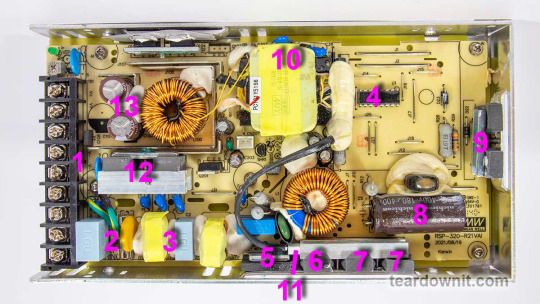
The RSP-320-24 is a 24-volt power supply with a maximum current of 13.4 amps. The supported mains voltage is from 100 to 240 volts without an additional switch. The supply measures 8.5 × 4.5 × 1¼ inches (215 × 115 × 30 millimeters), made on a printed circuit board fixed to the base's case. The top cover is perforated at the back near the connection terminals and on the front, where the cooling fan is installed. The fan starts spinning even if there's no electrical load. As the load increases, the fan speeds up, following the load current value. The fan sucks in the air and pushes it through the internal case volume to the perforated holes, including those on the side walls.
The input and output circuits are connected to a standard screw terminal block (1), from right to left: 3 terminals for the input line, neutral and ground wires, and 3 in parallel for common and +24V output. The input voltage from the terminals goes to the fuse (2), then to the pulse limiter (varistor), followed by the RF interference filter (3), and finally to the diode bridge (5). Next comes the active PFC, controlled by the PFC+PWM controller FAN4800 (4). Indeed, with a 234-volt AC power input, we get a rectified voltage on the storage capacitor (8) of 377 volts, approximately 47 volts more than without PFC Boost. The small voltage reserve is confusing since the capacitor installed is rated for 180 uF and 400 volts. All that's left is to rely on Nichicon's quality control.
The power part of the PFC is made of two parallel MOSFETs, IPP60R280P6 (7) and on an ultrafast diode 8A 600V STTH8S06D (6). The temperature sensor (11) is mounted above the PFC elements. The output voltage from the PFC is supplied to the two-transistor forward converter; the transistors are IPP60R280P6 (9) and are controlled by the same FAN4800 controller. The transformer (10) converter voltage is rectified and supplied to the LC filter. The output rectifier comprises eight diodes connected in two parallel groups (12). Total output capacitance: 2 pieces of 1000uF, 35V, designed for operating temperatures up to 220°F (105°C) (13). The output high-current circuits are reinforced with tinned copper busbars.
The control signal from the high-voltage side to the low-voltage side is transmitted through transistor optocouplers (there are two of them in the photo above the transformer hidden under a blob of the compound). One optocoupler is the primary regulation channel, and the second forms a backup channel for overvoltage protection, OVP.
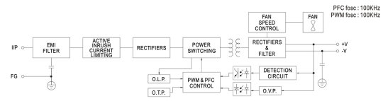
The block diagram in the datasheet shows the "Active Inrush Current Limiting" node. Still, we could not find components on the board that could perform such a role. Still, the inrush current limitation element is present, marked as RTH1 on the board, and installed near the boost inductor PFC; most likely, this is an ordinary NTC.
The high-voltage part of the board, starting with the capacitor (8) and ending with the transformer leads (10), is coated on the high-voltage side with a protective composite, presumably epoxy-based, which further increases electrical safety.
There is additional insulation and a thin sheet of fiberglass between the aluminum case and the board (solder side).
The overall build quality is good.
Test conditions
Most tests use metering circuit #1 (see appendices) at 80°F (27°C), 70% relative humidity, and 29.8 inHg pressure. The measurements were performed without preheating the power supply with a short-term load unless mentioned otherwise.
The following values were used to determine the load level:
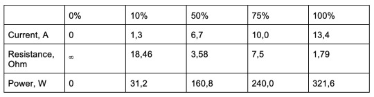
Output voltage under a constant load
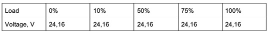
The high stability of the output voltage should be noted.
Power-on parameters
Powering on at 100% load
The power supply is turned off at least 5 minutes before the test, with a 100% load connected. The oscillogram of switching to a 100% load is shown below (channel 1 is the output voltage, and channel 2 is the current consumption from the grid):
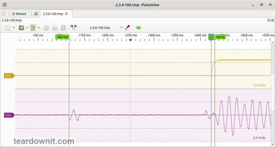
The picture shows three distinguishable phases of the power-on process:
The pulse of the input current charging the input capacitors when connected to the grid has an amplitude of about 2 A and a duration north of the mains voltage period.
Waiting for the power supply control circuit to start for about 300 ms.
(Output Voltage Rise Time) Starting the converter, increasing the output voltage, and entering the operating mode takes 8 ms.
(Turn On Delay Time) The entire process of entering the operating mode from the moment of powering on is 315 ms.
(Output Voltage Overshoot) The switching process is aperiodic; there is no overshoot.
Powering on at 0% load
The power supply is turned off at least 5 minutes before the test, with a 100% load connected. Then, the load is disconnected, and the power supply is switched on. The oscillogram of switching to a 0% load is shown below:
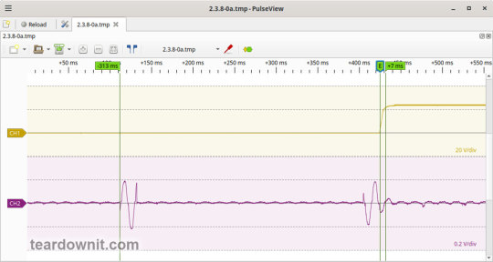
The picture shows three distinguishable phases of the power-on process:
The pulse of the input current charging the input capacitors when connected to the grid has an amplitude of about 2.2 A and a duration slightly longer than one mains period.
Waiting for the power supply control circuit to start for about 300 ms.
(Output Voltage Rise Time) Starting the converter, increasing the output voltage, and entering the operating mode takes 7 ms.
(Turn On Delay Time) The entire process of entering the operating mode from the moment of powering on is 320 ms.
(Output Voltage Overshoot) The switching process is aperiodic; there is no overshoot.
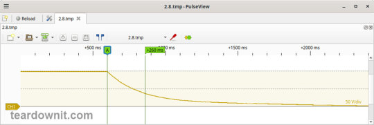
Power-off parameters
The power supply was turned off at 100% load, and the input voltage was nominal at the moment of powering off. The oscillogram of the shutdown process is shown below:
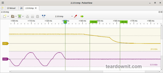
The picture shows two phases of the shutdown process:
(Shutdown Hold-Up Time) The power supply continues to operate due to the input capacitors holding charge until the voltage across them drops to a certain critical level, at which maintaining the output voltage at the nominal level becomes impossible. The phase takes 14 ms.
(Output Voltage Fall Time) Reduction of the output voltage, stopping voltage conversion, and accelerating the voltage drop takes 18 ms.
(Output Voltage Undershoot) The shutdown process is aperiodic; there is no overshoot.
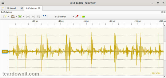
Right before shutdown, the current waveform at 100% load is close to sinusoidal with an amplitude of 4.22 A.
Ripple output voltage
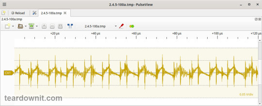
100% load
At 100% load, the low-frequency ripple is approximately 3 mV.
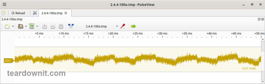
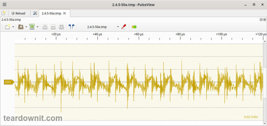
At 100% load, the ripple at the converter frequency is approximately 50 mVp-p, and the noise is 120 mVp-p.
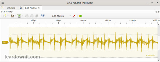
75% load
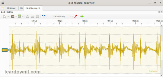
At 75% load, the low-frequency ripple is approximately 3 mV.
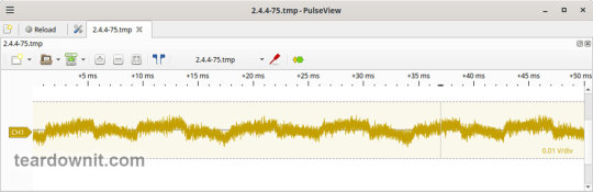
At 75% load, the ripple at the converter frequency is approximately 40 mVp-p, and the noise is 120 mVp-p.
50% load
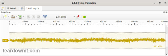
At a 50% load, the low-frequency ripple is approximately 3 mV.
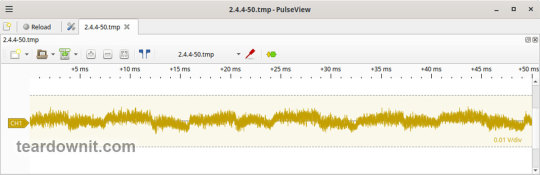
At 50% load, the ripple at the converter frequency is approximately 30 mVp-p, and the noise is 70 mVp-p.
10% load
At 10% load, the low-frequency ripple is approximately 2 mV.
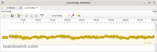
At a 10% load, the ripple at the converter frequency is approximately 20 mVp-p, and the noise is 90 mVp-p.
0% load
No-load current consumption measured with a multimeter: 53.5 mA.
(Power Consumption) The first assumption of excessive standby power draw of more than 6.5 watts is wrong since the current in this mode is predominantly reactive. Indeed, the input filter in the circuit contains two capacitors with a combined capacitance of 1.5 μF. Measuring the exact active power consumption at a 0% load with a basic set of instruments (oscilloscope, multimeter, etc.) is impossible.
At 10% load, the low-frequency ripple is approximately 2 mV.
At 10% load, ripples at the converter frequency are masked by the 90 mVp-p noise.
Dynamic characteristics
TA mode with periodic switching between 50% and 100% load was used to evaluate the dynamic characteristics. The process oscillogram is shown below:
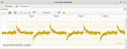
It is evident that the supply’s response to loading changes is close to aperiodic, and there is no overshoot, which indicates a good stability margin. The magnitude of the response to load changes is just 60 mV.
Overload protection
The claimed protection type is "hiccup mode, recovers automatically after fault condition is removed." This was confirmed during testing. When a short circuit occurs, the power supply periodically tries to turn back on and, if the overload is still present, turns off again until the next attempt. This operating mode reduces energy losses and heating during overload. Still, it does not allow the parallel connection of multiple power supplies with a common output.
The output current for the overload protection to kick in is 17 A.
Input circuit safety assessment
(Input discharge) Safety assessment is based on the discharge time constant of the input circuits when disconnected from the grid; the value is 0.26 s. This means that when operating on a 120 V input voltage, the time required to discharge the input circuits to safe values (<42 V) will be 0.41 s:
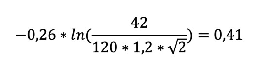
Important: The result is valid for this particular power supply unit; it was obtained for testing purposes and should not be taken as a safety guarantee.
The leakage current at the ground pin is less than 10 µA.
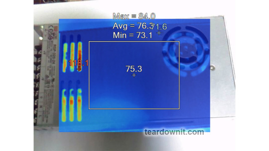
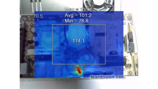
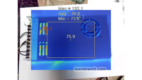
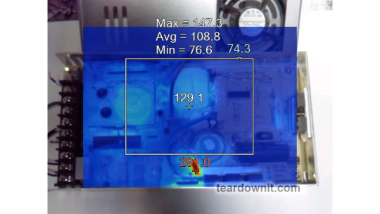
Thermal conditions
When operating with no load connected, no component overheating had been noticed. Thermograms were captured at three power levels: 80, 90, and 100%, fully assembled and with the lid removed. Thermal images show that the most loaded element of the block is the input diode bridge, and its heating seriously stands out against the background of all the other components.
Unfortunately, already at 80% load, the diode bridge heats up to an unacceptable level of 259°F (126°C), which is dangerous for long-term operation.
80% load
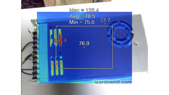
90% load
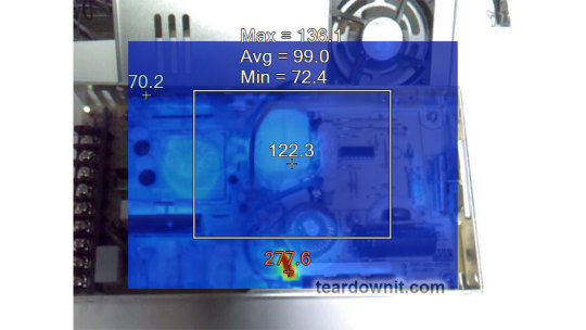
100% load
Conclusions
Overall, the RSP-320-24 is well-built: this power supply has good dynamic characteristics, low noise, and ripple, good accuracy in maintaining the output voltage, and is well put together. The load should be limited to 70–80% of the nominal for long-term operation.
Important: The results are valid for this particular power supply unit; they were obtained for testing purposes and should not be used to evaluate all the units of the same type.
0 notes
Text
WPI Youshang Group launches PD3.1 power adapter solution based on onsemi products

【Lansheng Technology News】Recently, Youshang launched a PD3.1 power adapter solution based on ON Semiconductor NCP1680, NCP13994, NCP4306 and FAN65004 chips.
With the promulgation of the USB PD3.1 protocol, fast charging technology has also ushered in a new era. Compared with the previous mainstream PD3.0 standard, the PD3.1 standard not only adds three expanded output voltages of 28V, 36V, and 48V, but also increases the maximum output power from 100W to 240W, which breaks through the existing high-power usage scenarios. , is expected to expand fast charging standards to new application areas. In order to accelerate USB PD3.1 charging design, WPI Youshang launched a PD3.1 power adapter solution based on onsemi NCP1680, NCP13994, NCP4306 and FAN65004 chips, which can bring users an efficient charging experience.
Onsemi's NCP1680 is a CrM totem pole PFC controller. It has two built-in half-bridges, one driven by PWM switching frequency for PFC boost. The other half-bridge performs synchronous rectification at AC frequency, thereby eliminating rectifier bridge losses in traditional rectifier circuits, improving conversion efficiency, and reducing heat dissipation requirements. In addition, the NCP1680's internally compensated digital loop control uses a constant on-time CCM architecture with valley switching functionality. And cycle-by-cycle current limiting is achieved without the need for Hall-effect sensors.
The NCP13994 is a high performance current mode controller for half-bridge resonant converters in offline power supplies. Its integrated X2 capacitor discharge, startup current source and gate driver simplify layout and reduce the number of external components in the power supply. And the NCP13994 has a dedicated output that can be connected to a PFC controller in applications that require a PFC preamplifier.
NCP4306 is a synchronous rectification controller designed to control synchronous rectification MOSFETs in switch mode power supplies. The controller can be used in various topologies such as DCM or CCM flyback, quasi-resonant flyback, forward and Half-Bridge Resonance LLC.
The FAN65004 is a wide VIN, high-efficiency synchronous buck regulator integrating high-side and low-side power MOSFETs. The device uses a fixed-frequency voltage-mode PWM controller to provide complete protection functions, including over-current protection, thermal shutdown, under-voltage lockout, over-voltage protection, under-voltage protection and short-circuit protection.
In addition to the above devices, this solution is also equipped with NCP58921 GaN devices, NTMT064N65, NCP51530 and other products, which can further improve charging efficiency and stability. In the future, as fast charging technology continues to evolve towards higher charging power, its application scope will be further expanded. During this process, Dalianda will continue to provide customers with high-quality fast charging solutions to help everyone quickly enter the era of fast charging for everything.
Lansheng Technology Limited, which is a spot stock distributor of many well-known brands, we have price advantage of the first-hand spot channel, and have technical supports.
Our main brands: STMicroelectronics, Toshiba, Microchip, Vishay, Marvell, ON Semiconductor, AOS, DIODES, Murata, Samsung, Hyundai/Hynix, Xilinx, Micron, Infinone, Texas Instruments, ADI, Maxim Integrated, NXP, etc
To learn more about our products, services, and capabilities, please visit our website at http://www.lanshengic.com
0 notes
Text
The Best Skylake-X CPUs Motherboards
TIM gate, VRM disaster? Possible X299 motherboard faults and Skylake-X
In recent weeks, the leaf and video forest has been quiet. Even a VRM disaster or TIM gate (hot paste instead of lot) were discussed, but if you examine closely, the G… Thermal paste instead of solder Intel’s choice of improper (but cheaper) thermal paste instead of indium-based solder contributes to the cooling issue. Discuss the shelf life now… Default Settings Outside the Box, Cheats, Heat Long before launch, motherboard manufacturers made the first critique.
A typical all-in-one compact water cooler has dozens… We hold motherboard makers accountable. Blaming the imminent heat inferno just on Intel and the CPU cranked to its maximum limit would have been too short-sighted.
Noise across all media has been scarce in recent weeks. There was even discussion of a VRM disaster or TIM gate (thermal paste instead of solder), but the whole thing is just a long causal chain that starts with a hot-headed CPU. In theory, there are three. We try to make it simple, so one after another.
(1) Skylake-X is hardly coolable out-of-the-box in typical use due to excessive power consumption and thermal paste that limits optimal heat dissipation.
(2) The average user has little overclocking room, and many motherboards limit the CPU owing to design issues like insufficient external voltage converter cooling. Extreme overclockers barely work with modern hardware.
Usually, too much rhetoric is added, which doesn’t do credit to the potential purchasers’ difficulties.
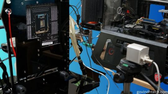
Test setup and measurements
We’ll acquire a simpler Socket 2066 motherboard, make a vertical benchtable, and test (or not). We’ll look at the sensor values and origins of the respective areas, and we’ll use the infrared thermal imaging camera to test the board’s heating around the socket and voltage converter for plausibility.
We can also record the heating process in time-lapse videos. We also want to know if motherboard hotspots or heat transfer damage other components.
For safe sensor readings and smooth test setup operation, we use the newest motherboard BIOS and HWinfo in the latest beta version from v5.53–3190 (click on beta version while downloading!). We fixed or deepened certain features after a deeper inspection, manufacturer check, and community suggestions.
The board’s CPU power supply has 5 1 phases controlled by an International Rectifier IR35201. This multi-phase buck controller supports Intel VR12 and evidently VR13. The so-called doubling allows two circuits per phase with five phases, relieving the individual VRMs and equalising hotspots in area. This chip’s voltages and currents will be discussed later.
Each control circuit uses one International Rectifier IR3555 voltage converter. These highly integrated power stage chips include gate drivers, high- and low-side synchronous MOSFETs, and the Schottky diode. Unlike other MOSFETs, they have analogue temperature sensors. How else can you accurately measure these voltage converters’ temperatures without an IR camera?
MSI employs the Nuvoton NC6795D as a Super IO chip on the tested motherboard to record and provide sensor information. With a central thermistor between the power stage chips, the voltage converters’ temperature is likewise measured. Thus, we choose the back measuring point below this thermistor for our video acquisition.
The coils and capacitors of these voltage converter circuits and the board temperatures up to the CPU are also checked.
Sudden shutdown and downclocking
To better comprehend the future testing and the concerns that were often addressed too polemically in forums, we must realise that motherboard makers use safety devices. The Skylake-X is clocked down to 1.2 GHz at exactly 105°C at the thermistor (HWinfo under line MOS, Nuvoton NCT6795D) by our test board until the temperature drops below 90°C. Only then does it reach full velocity.
This makes sense since the flash point for the PCB material (FR4) is much higher, but the maximum continuous operating temperature is only between 95 and 105°C to avoid dry-out, bending, and conductor path hairline cracks in multilayer PCBs. This is good because graphics card makers normally have more (unnecessarily) nerve in this area.
In Intel’s Extreme Tuning Utility (XTU), this downclocking termed Thermal Throttling: Yellow, yes. What about Motherboard VR throttling status indicators? We must also give a little addendum regarding HWInfo values. It is less well known that the IR35201 also measures temperature. These results for VR T1 and VR T2 are much higher and appear to contradict the external sensor.
As usual, only the controller chip temperature was output. This would be equivalent to voltage converter temperatures VRM1 and VRM2 on graphics cards with PWM controllers (AMD cards commonly utilised them) in various tools. Usually, the chip measured itself there. However, with IR35201 and IR3555, it can be presumed that the IR3555’s voltage values and temperature inside are also utilised.
Before the XTU yellow warns of motherboard VR throttling, these values are limited to 125°C and the CPU is clocked to 1.2 GHz. Because voltages could run outside specifications and damage hardware above 135°C, the motherboard is turned down without notice.
CPUs also protect themselves. Multiple integrated digital temperature sensors (DTS) determine the computing core and package temperatures. The precision of these calculations rises with temperature. Below 40°C, it’s irrelevant, but from 80°C, it’s accurate. We can also see that core and package temperatures can cause clock throttling.
The power loss of the IVR the CPU’s voltage converters that provide partial voltages is also included in package temperatures. With strong overclocking and manual voltage increase, unanticipated limit overruns might occur quickly, which not all tools can detect. So the CPU throttles without the user knowing why. The IVR will be discussed shortly.
0 notes
Text
Efficiency and Performance of International Rectifier's IRPT1058A Power Module
USComponent is proud to offer the IRPT1058A as part of our commitment to providing state-of-the-art solutions that empower industries to achieve more, efficiently and sustainably.
In power electronics, where efficiency and reliability are paramount, the International Rectifier IRPT1058A power module stands as a beacon of innovation. Engineered to meet the rigorous demands of modern industrial applications, this module represents a significant leap forward in power semiconductor technology.
Power and Performance Redefined
The IRPT1058A power module is designed with the utmost precision to deliver unparalleled performance in power conversion and control. Its advanced features include:
High Efficiency: With efficiency ratings that exceed industry standards, the IRPT1058A ensures minimal power loss during operation, thereby reducing energy consumption and operational costs.
Compact Design: Despite its robust capabilities, the module boasts a compact form factor, making it ideal for applications where space is at a premium without compromising on performance.
Reliability: Built to withstand harsh environmental conditions and operational stresses, the IRPT1058A offers unmatched reliability and longevity, ensuring continuous operation even in challenging environments.
Applications Across Industries
The versatility of the IRPT1058A extends across a wide range of industries, including:
Renewable Energy: In solar and wind power systems, where efficient energy conversion is critical for maximizing output and minimizing environmental impact.
Industrial Automation: In motor drives, UPS systems, and industrial machinery, where reliability and precision are essential for uninterrupted operation.
Electric Vehicles: As a key component in electric vehicle charging systems and power management, contributing to the efficiency and reliability of next-generation transportation solutions.
Technological Advancements
At the heart of the IRPT1058A lies cutting-edge technology that sets it apart:
Advanced Semiconductor Materials: Utilizing state-of-the-art silicon carbide (SiC) technology, the module achieves higher switching frequencies and lower switching losses, enhancing overall system efficiency.
Integrated Design: Featuring integrated gate drivers and protection circuits, the IRPT1058A simplifies system design and reduces component count, thereby optimizing installation and maintenance efforts.
Conclusion: Embracing the Future of Power Electronics
As industries worldwide continue to evolve towards greener, more efficient technologies, the International Rectifier IRPT1058A emerges as a pivotal player in the landscape of power electronics. Its combination of high efficiency, compact design, and robust reliability makes it the preferred choice for engineers and designers seeking to push the boundaries of innovation.
Whether in renewable energy systems, industrial automation, or electric vehicles, the IRPT1058A power module represents not just a technological advancement but a commitment to shaping a sustainable future powered by cutting-edge semiconductor solutions.
In conclusion, the IRPT1058A from International Rectifier is a testament to the convergence of efficiency, reliability, and innovation in power electronics, poised to lead industries into a new era of energy management and industrial automation. For more information on how the IRPT1058A can transform your power management systems, visit https://www.uscomponent.com/buy/International_Rectifier/IRPT1058A or contact us today.
#MOSFET#Transistors#MOSFET Transistor#Power MOSFET#Power Module#International Rectifier#International Rectifier Company#International Rectifier Corporation#International Rectifier MOSFET#International Rectifier Distributor#International Rectifier Semiconductor#Infineon acquires International Rectifier#Infineon and International Rectifier#IRPT1058A
0 notes
Text
ZPST series welding diodes are designed specially
Yangzhou Positioning Tech. Co., Ltd is located in Yangzhou city, Jiangsu Province, she is a stock company, which invests in many domains and factories. The main products include 0.6A - 18000A thyristors (Phase Control Thyristors- Stud & Capsule package), triac, REVERSE CONDUCTING THYRISTORS(RCT), Asymmetric thyristors, Bi-Directional Control Thyristor, series diodes(Standard and fast Recovery Diodes- Stud & Capsule package), bridge rectifier, MOSFET, transistor, triac, thyristor-thyristor modules, thyristor-welding diode, single diode and thyristor modules ,FRED Modules, solid state relays etc.


Our component products are widely used for industries, public utilities and military projects. Such as transportation,marine/rail propulsion systems, wind power converters, electrochemical power supplies, soft starters, motor control, lighting control, power factor compensation, electric vehicles, UPS, Inverter, DC chopper drives, Pulse Power applications, welding, Locomotive traction, induction heating and furnaces, Steel melt shop and foundry industry, electrochemistry and military electronics.
Backed with years of experience in international business, hundreds of skillful workers in the area, and great contribution of our staff, we have been one of the major suppliers today in China and the brand YZPST is also famous in the semiconductor field . Our goal is to become the best green and energy-saving semiconductor component supplier in the industry and make due our contribution to energy conservation and emission reduction.
We're sure you will always get our feedback with the quick speed from us once getting your inquiry. Please contact us with your detail information.
0 notes
Text
Baoding Jinkai Automation Technology Co., Ltd.
www.weldedpipetube.com
E-mail:[email protected]
------------------------------------------
Solid state high frequency circuit board-GGP5#AV4/GGP5#AV5.
This is a solid-state high-frequency equipment circuit board
produced by regular manufacturers, including rectifier board,
phase-locked board, pulse board, drive board, power distribution
board, power filter board, DC protection board, AC protection board,
using regular international electronic components Welding is
completed, high-quality PCB board, no matter which country you
are in the world, I can quickly deliver it to you, so that your steel
pipe welding equipment can resume normal production smoothly
and promptly. MOSFET modules and fast recovery diode modules
are both genuine and regular channels. CS30063/CS30062 are
produced by regular manufacturers and are recognized by many
customers in China.
0 notes
Text
Add To Library Lt Spice
Adding SPICE Models from Manufacturers
Add To Library Lt Spicewood
Add To Library Lt Spices
Ltspice Add Library
Add To Library Lt Spicewood

The websites of manufacturers are often great resources for additional SPICE models that can be used in Micro-Cap. For importing models into Micro-Cap, the Component Editor provides two wizards, the Import Wizard and the Add Part Wizard, or the user may also add the model manually. The Import Wizard provides the simplest route to importing models and will be the method desribed in this article. For information about the other two methods, reference the Working with Subcircuits chapter in the User's Guide. For this article, three models were downloaded from the internet and placed in a text file called Vendor.lib. Typically, a model file downloaded from the internet can be used directly with the Import Wizard. The Vendor.lib file was created to demonstrate the three possible outcomes that can occur when using the Import Wizard. The three models in the Vendor.lib file are: AD827 (Analog Devices) - High speed, low power opamp AD8145 (Analog Devices) - High speed, differential receiver IRFE330 (International Rectifier) - 400V N-Channel MOSFET The recommended location to place the downloaded file is the LIBRARY folder under the main Micro-Cap folder. The recommended extension of the file is .LIB. Neither of these are requirements though. Once the file is on the hard drive, the first step in importing the models is to access the Component Editor under the Windows menu. The Component Editor manages all of the circuit components used in the schematics. In the Component Editor, select the group that you want to import these parts into. The component tree on the right hand side of the Component Editor sets the structure of the Component menu in the schematic editor. Double click on a group name to open or close the group. The Add Group icon can also be used to add a new group to the tree. Highlight the group name that the parts should be in. Then invoke the Import Wizard by clicking on the following icon in the Component Editor toolbar. The first page in the Import Wizard is the File page which is shown below. This page specifies the library file that contains the models to be imported. The Browse button lets you browse through the hard drive to locate the library. In addition, an option called 'Copy the above file to the library directory' is available. When enabled, this option will copy the library file into the specified path. This option is useful in relocating the library file to the defined library path if it was downloaded into a different folder. Once the library file has been selected, click Next.


LTspice: Simple Steps to Import Third-Party Models. By Gabino Alonso. It is possible in LTspice IV to create a new symbol from scratch for a third-party model but who has the time? Follow these easy steps to generate a new symbol for a third-party model defined in a subcircuit (.SUBCKT statement). Inside C: Program Files LTC LTspiceIV lib will be three more folders, cmp, sub and sym. It is a good idea to bookmark this location for future use. Click Favorites and add a suitable name. To add for example the CMOS4000 library, download the files CD4000.lib and CD4000.zip. Once you have the Spice model on your computer, adding it to your LTspice library is very easy. Simply copy the file to your LTC LTspiceIV lib sub folder. Usually the full path to that directory will be either C: Program Files (x86) LTC LTspiceIV lib sub on a 64 bit Windows 7 installation or C: Program Files LTC LTspiceIV lib sub on a 32 bit.
Add To Library Lt Spices
The next page in the Import Wizard is the Suffix page which is shown below. This page specifies an optional suffix that can be added to all of the subcircuit names within the library file. To add a suffix, enter a string in the 'Suffix to Append to SUBCKT names' field and then click the Append button. This will rewrite all of the subcircuit names in the library file to include this suffix. Note that upon clicking Append, the library file is modified and saved to the hard drive. If the wizard operation is later cancelled, the library file will still contain the modified subcircuit names. An appended suffix can be useful when trying to import a model that has the same name as one that already exists in the component library. The Import Wizard only imports models that have a name that does not exist in the component library and adding a suffix will let the wizard import the model. In most cases, no suffix is needed and this page can be ignored as it will be in this example. Click Next.
After the Suffix page, the wizard starts the process of importing all unique models from the library file. Micro-Cap will compare the part(s) in the library to the existing parts in the Component Editor. For subcircuits, it compares both the amount of pins defined within the model along with the names of those pins to all existing subcircuit entries. There are three possibilities that can occur with each model in the library file. If it finds a single match, it will automatically add the part using the template of that match. If it finds no matches, it will place the part in the library with a generic template along with a designation that the part needs more work. If it finds multiple matches, a list of all of the available matches is then shown, and the template that is most applicable to the specified model can then be selected by the user. In addition to the list of matching templates, a second dialog box will also be invoked that displays the netlist of the model being imported. This netlist can often be useful in deciding which of the listed templates provides the best match. In this example, multiple matches are found for the IRFE330 device. The following two dialog boxes are then displayed.

Since the IRFE330 is an N-Channel MOSFET, the template based on the 2N6782 model which uses a DNMOS shape is selected. Clicking OK imports the IRFE330 using the same shapes and pin configuration as the 2N6782 device in the component library. Clicking Cancel will skip this component in the import process. Once all of the models in the library file have been processed, the Import Status page below will be displayed which lists the results of the Import Wizard operation.
The top section of the status listing describes the results for each individual model in the library file. For the AD827 model, a single match was found and the part has been imported in using a template defined by the AD645_AD component. For the AD8145 model, no match was found and the part has been imported in using a generic template. Note that this part has been flagged with a Needs Work label. For the IRFE330 model, the part has been imported in using a template defined by the 2N6782_IR component which was selected in a prior step. The bottom section of the status listing describes the total results for the library file. In this case, three subcircuit models were found in the file, and all three were imported. Click Finish to complete the import process. The parts will now be available in the Component Editor within the group that was selected when the Import Wizard was launched. Double check the parts to make sure the shape and the pin connections are correct. Highlight a part and then click on the Info icon in the toolbar. This will display the SPICE listing for the device which usually contains comments on the pin functions. Drag on the red dots to move the pin connections around as needed. At this point, you can edit the component just like any others in the Component Editor. For this example, the AD827 and IRFE330 need no additional work. The AD8145, which states Needs Work next to the component name in the tree to the right, needs a shape assigned and pins moved to the appropriate locations. Selecting a shape such as Opamp7d and then dragging the pin connections to the ends of the appropriate leads completes the importation of the AD8145.
Ltspice Add Library
Return to the main Newsletter page
0 notes
Text
Power Electronics Market to Observe Exponential Growth By 2026
Market Highlights
Global Power Electronics Market spans across North America, Europe, Asia-Pacific, the rest of the world.
The growing trend of renewable energy resources and portable energy systems is largely impacting the growth of the global power electronics market during the forecast period. However, complexities in designing and integrating technically advanced devices are expected to impact market growth. Power electronics devices are also used in electric and hybrid vehicles to optimize overall system cost, maximize power savings, extend mileage, minimize power losses, increase power density, and improve battery efficiency. This has created opportunities for manufacturers of power electronic components.
The geographic analysis of the power electronics market has been done for North America, Europe, Asia-Pacific, the rest of the world. Asia-Pacific has dominated the power electronics market in 2019 and is expected to reach USD 24.22 billion in 2026, with the highest CAGR of 7.78%. The regions of North America and Europe are also expected to witness significant growth over the forecast period.
In North America, the US accounted for the largest market share in 2018. Advancements in technology and the increasing demand for consumer electronics such as mobile phones, computers, and others are some of the major factors, which are driving the growth of the power electronics market in the region. Europe is expected to register steady growth in the power electronics market during the forecast period owing to the rising adoption of smartphones, increasing availability of smart devices, and other IoT-based systems. The region, by country, has been segmented into the UK, Germany, France, and the rest of Europe. Asia-Pacific dominates the power electronics market based on the region due to growing markets of consumer electronics and wearable products in China, India, Japan, South Korea, Singapore, Taiwan, and other countries in the region. Additionally, growing investments by key market players operating in this region significantly contribute towards the market growth. Furthermore, the increasing ownership of smartphones, personal electronics, and smart wearables in the region stimulates market growth. The rest of the world held the fourth position in terms of market share in 2019. The market growth in this region is currently stagnant due to the presence of emerging economies and relatively low infrastructure support. However, the market is expected to experience a growing trend in the future due to the increasing investment to boost the telecom infrastructure and IoT connectivity. The region has been segmented into the Middle East & Africa and South America.
Get Free Sample Report @ https://www.marketresearchfuture.com/sample_request/1069
Key Players
The Key Players of the global power electronics market are Alpha & Omega Semiconductor (AOS) Europe, AMS AG, Analog Devices Inc, Dialog Semiconductor, Diodes Incorporated, Semiconductor Component Industries LLC, Infineon Technologies AG, Renesas Electronics Corporation, Maxim Integrated, Microchip Technology Inc., STMicroelectronics, Texas Instruments, Toshiba Electronic Devices & Storage Corporation, Vishay Intertechnology Inc., and Allegro Semiconductors, among others.
Global Power Electronics Market: Segmentation
The global power electronics market has been segmented based on component, wafer type, wafer material, wafer size, application, and region. Based on component, the global market has been segmented into diodes, thyristor, MOSFET, AC/DC converter, static switches, and others. By wafer type, the market has been segmented into Silicon, GaN, SiC, and others. Based on wafer material, the market has been bifurcated into N-type and P-type. By wafer size, the market has been segmented into 150mm, 200mm, 300mm, and 450mm and above. Based on application, the global power electronics market has been segmented into consumer electronics, IT & telecommunications, automotive, aerospace & defense, industrial, energy & utilities, transportation, and others.
Table of Content:
3 RESEARCH METHODOLOGY
4 MARKET DYNAMICS
4.1 OVERVIEW
4.2 DRIVERS
4.2.1 INCREASING FOCUS ON DEVELOPING POWER INFRASTRUCTURE AND THE USE OF RENEWABLE POWER SOURCES
4.2.2 RISING USE OF POWER ELECTRONICS IN PORTABLE ENERGY SYSTEMS
4.3 RESTRAINT
4.3.1 COMPLEX DESIGN AND INTEGRATION PROCESS OF ADVANCED TECHNOLOGICAL DEVICES
4.4 OPPORTUNITIES
4.4.1 GROWING DEMAND FOR HEVS AND EVS
4.4.2 DEMAND FOR GAN AND SIC POWER SEMICONDUCTORS
4.5 CHALLENGE
4.5.1 UNSOLVABLE STRATEGIC ISSUES OF THE SEMICONDUCTOR INDUSTRY
4.6 IMPACT ANALYSIS OF COVID-19
4.6.1 IMPACT ON SEMICONDUCTOR MANUFACTURERS
4.6.2 IMPACT ON COMPONENT MANUFACTURERS
4.6.3 IMPACT ON DEVICE MANUFACTURERS
4.6.4 IMPACT ON SUPPLY CHAIN DELAYS
5 MARKET FACTOR ANALYSIS
5.1 SUPPLY CHAIN ANALYSIS
5.1.1 RESEARCH & DEVELOPMENT CENTER
5.1.2 MATERIAL SUPPLIERS AND FOUNDRIES
5.1.3 COMPONENT MANUFACTURERS
5.1.4 SUBSYSTEM INTEGRATORS
5.1.5 END USERS
5.2 PORTER'S FIVE FORCES MODEL
5.2.1 THREAT OF NEW ENTRANTS
5.2.2 BARGAINING POWER OF SUPPLIERS
5.2.3 THREAT OF SUBSTITUTES
5.2.4 BARGAINING POWER OF BUYERS
5.2.5 INTENSITY OF RIVALRY
6 GLOBAL POWER ELECTRONICS MARKET, BY COMPONENT
6.1 OVERVIEW
6.2 DIODES
6.3 THYRISTOR
6.3.1 SILICON CONTROLLED RECTIFIER (SCR)
6.3.2 GATE TURN-OFF TRANSISTOR (GTO)
6.3.3 MCT (MOS-CONTROLLED THYRISTOR)
6.4 MOSFET
6.5 AC/DC CONVERTER
6.6 STATIC SWITCHES
6.7 OTHERS
Get Complete Report @ https://www.marketresearchfuture.com/reports/power-electronics-market-1069
About Us
Market Research Future (MRFR) is an esteemed company with a reputation of serving clients across domains of information technology (IT), healthcare, and chemicals. Our analysts undertake painstaking primary and secondary research to provide a seamless report with a 360 degree perspective. Data is compared against reputed organizations, trustworthy databases, and international surveys for producing impeccable reports backed with graphical and statistical information.
We at MRFR provide syndicated and customized reports to clients as per their liking. Our consulting services are aimed at eliminating business risks and driving the bottomline margins of our clients. The hands-on experience of analysts and capability of performing astute research through interviews, surveys, and polls are a statement of our prowess. We constantly monitor the market for any fluctuations and update our reports on a regular basis.
Media Contact:
Market Research Future
Office No. 528, Amanora Chambers
Magarpatta Road, Hadapsar,
Pune - 411028
Maharashtra, India
+1 646 845 9312
Email: [email protected]
0 notes
Text
Power Discrete Market Size, Trends, SWOT, PEST, Porter’s Analysis, For 2020–2026

The global Power Discrete Market is estimated to reach USD 20.36 Billion by 2026, according to a new report by Reports and Data. This can be mainly associated with the steadily growing demand for IGBTs (Insulated Gate Bipolar Transistors), the use of discrete silicon-based IGBTs which enhances the efficiency of electronic devices that range from consumer electronics to power electronics. The purpose of silicon-based IGBTs adds significantly to the advancement of power electronics. Based on statistics, the rise in demand for IGBTs will boost market growth. With increasing energy needs across the world, the power grid infrastructure is refurbished to generate more power, distribute and transmit it efficiently, and controls the consumption as per the demands of the end-user, hence propelling its need in the global power discrete market. In the industrial aviation sector, technologically advanced power discrete devices are achieving popularity to meet the ever-increasing electronic content in new generation aircraft.
Get a sample of the report @ https://www.reportsanddata.com/sample-enquiry-form/1236
The report covers in-depth profiling of the prominent players of the industry and includes Infineon Technologies AG, ST Microelectronics N.V., Mitsubishi Electric Corp., International Rectifier, ON Semiconductor Corp Vishay Intertechnology Inc., Vectron International, Fairchild Semiconductor International Inc., Toshiba Corp., Siward Crystal Technology, Fuji Electric Co Ltd, Renesas Electronics Corp, and Tongfang Guoxin Electronics among others. Furthermore, it offers a detailed analysis of the competitive landscape of the market with insightful data on recent trends, technological developments, product advancements, methodologies, and strategic business decisions such as mergers and acquisitions, joint ventures, collaborations, and product launches, among others.
It further offers critical insights on the regional bifurcation of the market with regards to market scope, market size, market share, revenue generation, production and consumption ratio, supply and demand ratio, and analysis of the key players operating in those regions. The regional analysis covers North America, Europe, Asia Pacific, Latin America, and Middle East & Africa.
The report studies dynamic market elements such as drivers, restraints, challenges, threats, opportunities, and growth prospects, among others. The report offers strategic recommendations to the new entrants as well as established players to assist them in capitalizing on the advantageous opportunities.
For the purpose of this report, Reports and Data have segmented global Power Discrete Market on the basis of Product, Application, End Users, Range and region:
Product Outlook (Volume, Thousand Units; and Revenue, USD Billion; 2016-2026)
Insulated Gate Bipolar Transistor (IGBT)
Gallium Nitride (GaN)
Power rectifiers
Metal Oxide Semiconductor Field Effect Transistor (MOSFET)
Silicon Carbide (SiC)
End User Outlook (Volume, Thousand Units; and Revenue, USD Billion; 2016-2026)
EV/HEV
Renewable Energy
Industrial Motor Drive
Application Outlook (Volume, Thousand Units; and Revenue, USD Billion; 2016-2026)
Automotive
Consumer
Medical
Cellular handsets and infrastructure
Lighting
Range Outlook (Volume, Thousand Units; and Revenue, USD Billion; 2016-2026)
Less than100V
100V to 600V
600V to 200V
1200V
Browse Complete Report @ https://www.reportsanddata.com/report-detail/power-discrete-market
Key Point Summary of the Report:
The global Power Discrete market research report is an investigative study offering key insights into the latest growth trends, developments, technological and product advancements, and the research and development scenario. The report also covers the market aspects that directly influence the growth of the market. These features include strategies undertaken by the prominent players, their expansion tactics, and the product portfolios of the companies, and micro and macro-economic factors.
The study also analyses the crucial market aspects, including R&D, product launches and brand promotions, mergers and acquisitions, collaborations, joint ventures, and the growth pattern on both regional and global levels. The report offers an in-depth evaluation of factors such as cost, capacity, rates of production and consumption, gross revenue, profit margin, demand and supply ratio, import/export, market share, market size, and market trends.
Key Question Addressed in the Report:
· What are the key driving factors of the Power Discrete industry?
· What will the market size and growth rate be throughout the forecast period?
· Who are the prominent players of the Power Discrete industry?
· What are the technological advancements and product developments taking place in the Power Discrete market?
· What are the key outcomes of the SWOT analysis and Porter’s Five Forces analysis?
· Which region is expected to dominate the market in the coming years?
· What are the key risk factors and challenges the companies will face in the market?
Table of Content:
Chapter 1. Market Synopsis
1.1. Market Definition
1.2. Research Scope & Premise
1.3. Methodology
1.4. Market Estimation Technique
Chapter 2. Executive Summary
2.1. Summary Snapshot, 2018-2026
Chapter 3. Indicative Metrics
Chapter 4. Power discrete Market Segmentation & Impact Analysis
4.1. Power discrete Market Segmentation Analysis
4.2. Industrial Outlook
4.2.1. Market indicators analysis
4.2.2. Market drivers analysis
4.2.2.1. Increasing demand for IGBTs
4.2.2.2. The use of discrete silicon-based IGBTs
4.2.3. Market restraints analysis
Continued….
Request for Customization of Report @ https://www.reportsanddata.com/request-customization-form/1236
Thank you for reading our report. Customization of the report is available based on the client’s requirements. For more details, kindly connect with us, and our team will ensure the report is suited to meet your requirements.
0 notes
Text
Silicon Carbide MOSFET GA100TS60SQ by GeneSiC Semiconductor Inc.
GA100TS60SQ is a silicon carbide (SiC) power module designed for high-power switching applications. It is manufactured by GeneSiC Semiconductor Inc. and consists of two SiC MOSFETs (Metal-Oxide-Semiconductor Field-Effect Transistors) and two anti-parallel diodes in a single module.
This power module has a maximum collector current of 100A and a maximum collector-emitter voltage of 600V. It features a low on-resistance, fast switching speed, and high thermal conductivity, making it suitable for use in high-frequency, high-temperature, and high-power applications such as electric vehicles, renewable energy systems, and industrial drives.
The GA100TS60SQ is designed for high reliability and efficiency, and it features advanced protection and monitoring features such as over-current protection, over-temperature protection, and under-voltage lockout. Its compact package design simplifies circuit design and assembly and provides high power density and thermal performance.
In summary, the GA100TS60SQ power module is an efficient and reliable solution for high-power switching applications that require fast switching speed, low on-resistance, and high-temperature performance. Its advanced features and high-power capability make it suitable for a wide range of industrial and automotive applications.
#Power Distribution Module#Silicon Carbide MOSFET#SIC MOSFETs#Power Module#International Rectifier#SIC Power MOSFET#SIC Power Module#SIC Module#Silicon Carbide Power Modules#Genesic Semiconductor Inc.#GA100TS60SQ
0 notes
Text
Sekelompok Inverter IGBT Sisitem Inverter
Punya ciri-ciri menarik sampai hingga nampak mengagumkan serta modern bisa kita kasih buat kamu secara free perancangan metode inverter, kalian bisa terjadi dengan cepat. Wujud menarik dapat kalian buat kalau kita cerdas waktu bikin metode inverter yang bisa kita kasih di bawah berikut ini dapat memberinya tambahan buah pikiran buat membikin metode inverter serta bisa memercepat kamu dalam pekerjaan metode inverter tiap-tiap hari.
Keterangan dan program IGBT dalam elektronik
Keterangan perincian dan program IGBT dalam elektronik penggunaan dalam inverter AC drive, VSD servo motor, Stepper power persediaan switching serta vector drive unsur IGBT dalam permesinan dan perabotan industri sudah sering digunakan.
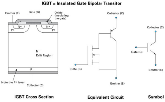
Transistor dwikutub gerbang terisolasi

IGBT sebagai feature semikonduktor yang serupa dengan gabungan suatu BJT dan Suatu MOSFET jenis feature anyar yang bertindak jadi sisi sakelar buat program daya. Ciri-ciri IGBT sama dengan namanya feature anyar ini merupakan feature yang jadikan satu skema.
Cara kerja IGBT buat fungsi fungsi
IGBT normalnya kerap difungsikan di sekelompok seperti inverter AC drive stepper vektor drive dan beberapa ppower persediaan yang pakai sistem switching cara kerja IGBT yang mirip dengan MOSFET bikin transistor ini kadang waktu disetarakan dengan MOSFET
Listrik inverter keterangan fungsi ragam tehnik

Wawasan Inverter merupakan satu sekelompok elektronika daya yang difungsikan buat mengkonversi atau mengubah tegangan searah DC jadi tegangan bolak balik AC Inverter merupakan kesebalikan dari converter adaptor yang punya andil mengubah tegangan bolak balik AC jadi tegangan DC buat waktu ini.
Kamu tengah mencari IGBT, di tempat ini kami Jual IGBT Fuji Electric kamu bisa mendapatkan IGBT yang tengah kamu mencari, beberapa merek seperti Semikron, Infineon, Eupec, Hitachi, Siemens, ABB, Toshiba, Fuji Electric, Starpower, Mitsubishi, IXYS, INEC, International Rectifier (IR), Powerex, Sanrex, Powersem, Fanuc, Vishay, serta beberapa part number berada pada sini partelectro.com memberi harga terunggul buat kamu yang tengah mencari IGBT yang di buthkan buat sekarang.
0 notes
Link
Description: Type:Field-Effect TransistorBrand Name: International RectifierPackage Type: Throught HoleModel Number: IRFZ44NPBFTO-220AB: MOSFET N-Channel, Metal Oxide55V 49A: FETs – ...
0 notes