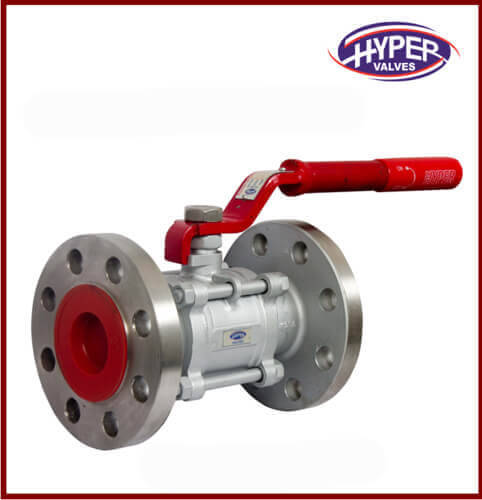
#PTFE Lined Pressure Relief Valve
Explore tagged Tumblr posts
Visit Tumblr Blog
Explore Tumblr blogs with no restrictions, modern design and the best experience.
Last Seen Tumblr Blogs


Fun Fact
Tumblr Inc. is using 66 technologies for its website.
Text
How to Choose the Best 1L Double Glazed Reactor for Your Lab: Key Features to Prioritize
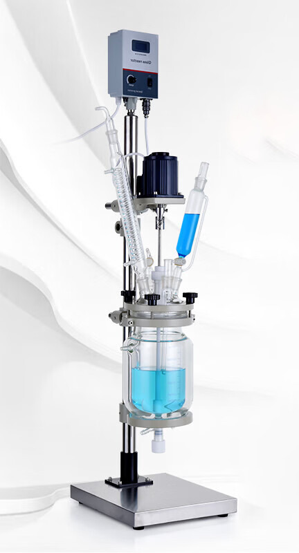
Selecting the right 1L double glazed reactor is critical for optimizing chemical synthesis, distillation, or crystallization processes in your lab. With varying designs and functionalities available, understanding core features ensures you invest in equipment that aligns with your research needs. This guide breaks down the must-have 1L double glazed reactor features, offering insights to help you make an informed decision—while subtly highlighting how EquilRxnLab’s solutions excel in these areas.
1. Material Quality and Durability
The foundation of any reliable reactor lies in its construction. Double glazed reactors use two layers of borosilicate glass to create an insulating vacuum, minimizing heat loss and ensuring thermal stability. When evaluating a 1L reactor:
Verify Glass Grade: High-quality borosilicate glass (e.g., GG17 or equivalent) resists thermal shock and chemical corrosion.
Check Joints and Seals: Reinforced PTFE or fluoropolymer seals prevent leaks during high-pressure reactions.
EquilRxnLab’s AKF-1L Double Glazed Reactor employs precision-engineered glass and chemically inert seals, making it ideal for prolonged use under aggressive conditions. Explore their full product catalog for detailed specifications.
2. Temperature Control and Uniformity
Precise temperature regulation is non-negotiable for reproducibility. Look for:
Integrated Jacket Design: A double-layered jacket allows uniform heat distribution via oil or water circulation.
Compatibility with External Systems: Ensure the reactor integrates with your lab’s chillers, heaters, or cryostats.
EquilRxnLab’s design includes a seamless jacket interface, enabling precise control from -80°C to 250°C. For visual guidance, their YouTube channel demonstrates setup workflows.
3. Stirring Mechanism Flexibility
Efficient mixing is vital for homogeneous reactions. Prioritize reactors with:
Adjustable Speed: A motor capable of 0–600 RPM (or higher) accommodates viscous or shear-sensitive mixtures.
Modular Stirrers: Interchangeable impellers (e.g., anchor, propeller, or paddle) adapt to different viscosities.
The AKF-1L reactor supports variable-speed motors and customizable stirring configurations, ensuring adaptability across experiments.
4. Safety and User-Friendliness
Labs demand equipment that minimizes risks. Key safety features include:
Pressure Relief Valves: Automatic pressure regulation prevents over-pressurization.
Stable Mounting Frame: A rigid stainless-steel stand reduces vibration and tipping hazards.
EquilRxnLab incorporates these safeguards into their reactors, alongside ergonomic clamps and intuitive control panels. Follow their Instagram for safety tips and user testimonials.
5. Scalability and Compatibility
A 1L reactor should integrate seamlessly with peripheral lab tools:
Standard Ground Joints: Ensure compatibility with condensers, dosing pumps, or sensors.
Modular Ports: Multiple openings for thermocouples, reflux setups, or vacuum lines enhance versatility.
The AKF-1L’s standardized joints and ports simplify system expansion, as showcased in EquilRxnLab’s Facebook tutorials.
6. Maintenance and Support
Long-term value depends on ease of maintenance and vendor reliability:
Detachable Components: Easy-to-clean parts reduce downtime.
Warranty and Technical Support: Opt for brands offering responsive customer service.
EquilRxnLab provides comprehensive manuals and dedicated support via their contact page, ensuring your reactor remains operational for years.
Conclusion Choosing a 1L double glazed reactor hinges on balancing material robustness, temperature precision, safety, and scalability. By prioritizing these features, labs can enhance experimental accuracy while minimizing operational risks. EquilRxnLab’s AKF-1L model exemplifies this balance, offering a reliable, adaptable solution for diverse applications. For hands-on demos or inquiries, visit their product page or connect via their social channels.
Final Tip: Always cross-reference technical specs with your lab’s workflow requirements. A well-chosen reactor becomes a cornerstone of efficient, repeatable science.
0 notes
Text
China Manufacturer valve R901017025 for steam turbine
"China Manufacturer valve R901017025 for steam turbine Selection of advanced technology, absolutely first-class service quality, YOYIK over the years to the same faith. The main technical backbone are retired senior engineer, senior mechanic. Many of them have participated in the planning, production and installation of power stations such as Gezhouba, Ertan and Three Gorges, and provided high-quality equipment selection, construction planning, installation and dispensing of hundreds of hydropower stations and overhaul of thermal power plants. , After-sales service and other train services.
Yoyik can offer many spare parts for power plants as below:
DF-valve R901017025-DF
electric oil transfer pump DLZB820-R64A-8 pressure hose SMS-12/20-1219mm-C sliding vane pump F3-317667 pump screw ACF-090N5 ITBP hydraulic vane pump F3-V20-1S8S-1C11 relief valve 1LOF-98H hydraulic motor 25LY-36 Check valve (clip type) 216C40 vacuum filter P-1759 piston pumps PV29 2R50 000 chemical pump centrifugal DFB80-50-220 Oil Pump Coupling Cushion KG70KY/7.5K5 reciprocating piston pump PVH074R01AA(AB)10A250000002001AB0 screw pump diagram PACG070K7NVB mechanic seal water pump 125-80-250 vacum pump air vacuum KZ/100WS sealing ring HB4-56J8-22 Fast return solenoid valve DF1-3 Dg-40 220VDC screw pump diagram HSNH4400Z-46NZ Check valve XYZ-16G balance diaphragm KC50P-97 Globe valve J941H-16C screw pump diagram ACG070-K7NVBP piston pumps PVT38-2R5C-C03-S00 vaccum pump P-1931A HYDROGEN DRYER COMPRESSOR 300FS1/2-F screw pump working HSNH80-27 pump mechanical seal BF108-45u pressure hose S110-AC-FC-0250 transfer oil pump SDSN65-100X2A wet solenoid directional valve 4WE10D3X/CG220NZ4 PTFE Lined Butterfly Valve 100DSF4PB3-16-100 BFP low pressure accumulator skin NXQAB-100/-10-L Fluoro Rubber O-Ring OR0030034 rotary vacuum pump P-1264 vacuum pump 223v 30-SPEN valve R901017025
vacuum pump vane F3-SDV20-1P11P-1A Servo valve G772 K240A electric oil pump 50IY50A pump vacuum 125LY-43BH DIRECTIONAL CONTOL VALVE T22BH-B6H gasket 03506-350/357/479 part no.:92 mechanical seal parts BKM79.4143B solenoid valve EVSI-DN25 BFP steam turbine governing and safety actuator YGM239 pressure hose SMS-10-1524-C liquid ring vacuum pump HSN280-43NZ piston hydraulic pump MOOG0514 7005 37 servo valve stem GU/3832-01 metering piston pump A3H37-F-R-01KK-10 mechanical seal for water pump FIJ125-100-315 bellows globe valve WJ50F1.6P Governor O-ring DH00.009 flexible shaft coupling A10VS0100DR/32R-VPB12N00 vacuum pump 220v MO1225OBGCC15A water pump DFB125-80-260 rotary vacuum pump ZS-185 burgmann mechanical seal 104-45 butterfly valve K125DSF4PB3 O-ring C8689085 electric motor centrifugal water pump DFB100-65-260-03 EH oil pump cushion PVH098R01AD30A250000002001AB010A mechanical seal 55 mm FIJ125-100-315 transfer pump fuel YW50-32-250A water pump DFB100-65-230 centrifugal pump DFB125-80-300 Industrial pump 8SH-6 solenoid valve 4WE6D62/EW220NZ5L hydraulic pump repair 125LY-35-4B multistage centrifugal pumps YCZ50-250B valve body ring 50-250C high pressure piston pump PVH141R13AF30A230000002001AB01A valve R901017025
DFYLSYC-2024-7-8-A
"
0 notes
Text

Keshav Encon is hiring
Position - Assistant Manager (Sales & Marketing) - Permanent role
Experience - 0 to 2 Years of Experience
Qualification: Diploma Mechanical or Chemical or instrumentation engineer
Product Range: Self-Actuated Pressure Control Valves, Manifold System for cylinder gases, Tank Blanketing Systems, Centrifuge Blanketing System, Safety Relief Valve, PTFE Safety Relief Valves for Glass Lined Reactors and corrosive services, Breather valves, Flame Arrestors, Breather Valve with Built in flame arrestor, Emergency Vents, and LPG & Natural Gas Conditioning, Regulating & Metering Skids
Location - Vadodara
Please share your resume on
Ms. Gargi +91- 9099463713
https://keshavencon.com/
#Job#Recruitment#Hiring#Jobplacement#Latestjobs#Overseasrecruitment#Recruiter#Keshavencon#Vadodara#India#newjobs#Vacancy#Engineers#Engineering#recruiting#career#employment#jobseekers#jobvacancy#jobopening#nowhiring#staffing
0 notes
Text
What is the goal of a control valve?
A control valve manages fluid flow by changing its size or direction in response to controller input. It aids in the direct control of flow rate and the regulation of other critical process variables, including temperature, liquid level/flow, and pressure. In automatic control terminology, it is also known as the "final control element."
In other words, a Safety Valve is used to regulate the flow, pressure, liquid level, and temperature of a system by entirely or partially opening or closing it in response to controller signals. The positioners control the closing and opening of the electric, hydraulic, and pneumatic actuators, which govern the opening and shutting of the control valve.
How does it work?
To offer constant quality goods, the process plant has several control loops. These control loops have a predetermined pressure, temperature, flow, and level to maintain the desired working range. Internal disturbances occur in each of these control loops, which are monitored by sensors and transmitters. The controllers subsequently analyze the acquired data, who determine what should be done to correct the load disruptions. A controlling element is implemented after the data has been examined, measured, compared, and calculated. The control valve enters the scene at this point and works to lessen the disturbances.
As a result, the control valve's working concept relies on manipulating flowing fluids like water, gas, steam, or chemical compounds to guarantee that load disturbance is minimized, and the process variable is regulated to the closest value of the desired set point.
Gate valves are used to open and close doors.
The Automatic Control Valve is made up of a flat barrier that may change the flow area. It has an on-off application and is well suited to regulate high temperature and pressure for various liquid flows. The valves that regulate the automated emergency cut-off and the hand-operated valves have this design or body.
THE BENEFITS OF A GATE VALVE
· It features an excellent Closing feature.
· In a circuit, it can be used in either direction.
· It creates laminar flow, resulting in minimal pressure loss.
GLOBE VALVE

The phrase "globe valve" refers to the outer shape of the valve, which is utilized for throttling. The globe valves have a stem that moves up and down in a linear motion to modify the position of the plug. It has a short stem journey, a lot of seating capacity, a lot of pressure drop, and flow controllability.
THE BENEFITS OF A GLOBE VALVE
· Has an excellent full-closing feature.
· Because the strokes are more minor, the valve opens and closes faster than a gate valve.
· Has a practical throttling feature.
· With little change in shaft disconnection, it can be used as a stop check valve.
PLUG VALVES
Plug valves are made up of a plug, a body, and a cover and are used for on-off services in refineries, chemical plants, and petrochemical plants. Typically tiny in size, they require less headroom and come in a variety of materials. They provide a tight seal, rapid opening, and minimal pressure drop.
· It is made up of only a few elements and has a straightforward design.
· Easily opens and closes.
· It is simple to maintain and repair at the location of operation.
· They offer a low flow resistance and a leak-proof feature that is trustworthy.
BALL VALVES
The pressure and flow of corrosive fluids, regular liquids, gases, and slurries are controlled by a ball valve. It also keeps high temperatures and stress under control.
BALL VALVES HAVE MANY BENEFITS
· Provides a leak-free service.
· Service that is quick to open and close.
· When compared to gate valves, it has a relatively modest size.
· In comparison to gate valves, it is lightweight.
· Has the ability to reduce the number of valves necessary by using a multi-way design.
· Under high temperature and pressure conditions, it provides dependable and safe service.
· When compared to gate and globe valves, it requires less force to operate.
DIAPHRAGM VALVES
For corrosive fluids at low temperatures and pressures, a diaphragm valve is utilized by deforming one surface with force from the valve stem.
ADVANTAGES OF DIAPHRAGM VALVES
· The diaphragm isolates the working parts from the process fluids completely.
· Construction is simple, making it easier to operate and maintain.
· It has hassle-free functioning due to its basic design and convenience of use.
· It can be utilized for a variety of purposes, including opening, throttling, and closing.
· It provides solid chemical resistance because it is based on the body's internal sheathing.
· There is no shaft leakage since the fluid is kept separate from the bonnet group.
· Heavy chemical, chemical, and radioactive fluids are all compatible.
· It can protect the system from microbiological contamination because the fluid is kept apart from the bonnet group, and it can be utilized in the food, pharmaceutical, and beer industries.
0 notes
Text
A Slab gateway valve with increasing stem shares almost all characteristics of any non-rising-stem counterpart.
BSP Threaded Brass Door Valve
The BSP Threaded Brass Gate Valve features a brass body, steel seat, and your PTFE seated wedge. The valve is actually rated for stress ranges of 0 in order to 16 BAR and will withstand media temps from -20 to help 120 degrees Celsius. It could be used with various gases and fluids. Read on to find out how to choose the right valve for the application. These valves can be purchased in a range involving styles and resources. Slab gate valve
Slab gate valve made of brass is any low-cost option regarding applications where strength and reliability are essential. Its non-rising stem and threaded stops enable it to become installed easily in various systems. Also, this material is usually inexpensive, making it a good solution for budget-conscious firms. Brass is also your best option for many alternative applications. In accessory, it has a high tensile strength plus has excellent use resistance.
Slab gate valves are generally used for gas and gas pipe-lines, but is usually used in that petrochemical industry, compound industry, or regarding other unique specialised requirements. They have a forged metal backseat and may be ordered having pressure relief, outflow detection, or grease injection, among other options. And, due therefore to their proven reliability, they are among the most famous valves in the market. Single expanding valve
A single extending brass gate valve is really a wedge valve that includes a flexible disc and also a rigid body. The disc expands because it is driven by a stem. Both sectors fit together, and also the gate expands to the seat to realize sealing. They are often easy to retain, and maintenance is possible without disassembling the valve from your process line. These valves may be either cast and also forged. They are often termed as "flex-wedge" valves.
The gates throughout an expanding control device are two slabs that match one other to provide finalizing by mechanical enlargement. When the gate is open, the actual media can move. When it is usually closed, the gateway blocks the movement. The gate is actuated by the upward force about one slab and by a downward force for the other. When your gate is d, the media is actually blocked. The gate in that case expands outward to produce the seal. This valve can be acquired with either a new manual or energy actuator. Slab control device with metal sitting wedge
A Slab control device with metal placed wedge is one method of gate valve. This type of valve is utilized to control flow isolation. Its metal seated wedge is constructed of ductile iron by using bronze rings that form a leak-proof seal. The palm wheel and blank disc are installed over the valve's leaves and seat. Its backseat protects that stem threads. SOME SORT OF wedge gate valve is installed flat or vertically.
A slab gate valve using a metal-to-metal seal has a grease injector on the exterior. Grease gets in to the sealing face through the injector along with the seat ring. A slab gate valve having a flow guide hole is known for a wedge disc installed about the sealing face. This kind of prevents the wrapping up face from eroding. The Slab control device with metal seated wedge is also suitable for high-temperature applications. Full port most important shutoff valve
Full port principal shutoff brass gate valves utilized for a range of applications. They can easily shut off drinking water and compressed air conditioning. They are as well available with non-rising arises, which are ideal when vertical breathing space is limited. Below are a few of the services these valves. They're highly durable, efficient, and cost helpful. These valves have a two-year limited warrantee. Learn more about some great benefits of full port brass gateway valves.
To swap a broken entrance valve, first take out the gate. Sometimes it is done by inserting a sheet of metal into the hole. This will make the valve stop the water flow.Brass Radiator Valve Manufacturers If this fix will not work, you have to replace the door valve. If you're unsure of how to perform the mend, contact a accredited master plumber. Changing or restoring a gate valve requires a nice selection of knowledge and skill. Never attempt to undertake the repair by yourself. You may wind up damaging the valve or causing on your own injury. Slab checkpoint valve with rising stem
A Slab gateway valve with increasing stem shares almost all characteristics of any non-rising-stem counterpart. The rising originate is attached directly into the gate, whereas the non-rising-stem valve includes a pointer threaded onto the top of the control device. These valves are ideal for applications with very low vertical clearance, like wells, and people who do not call for the valve to rise. They can also be suitable for guide actuation.
The RAYS Slab Gate Valve is manufactured with a full-bore port, rising-stem OS&Y, flying seats, and any forged steel shape. This type of valve will come in both Direct along with Reverse Acting configurations. The RAYS Srl By way of Conduit Slab Gate valve is a good choice for countless applications. The single piston design offers ease of maintenance and axial action.
0 notes
Text
What Is A PTFE lined ball valves?- A Complete Guideline
To Sum It UpA PTFE lined ball valves is essential when it comes to industries because it helps to regulate the flow and pressure of liquids passing through the pipe. The valve consists of a disc that is either perpendicular or parallel to the opening of the tube, and it regulates the pressure efficiently. For machines, it is essential to note that the proper functioning of all the parts is mandatory. Visit https://www.linedvalves.co.in/lined-ball-valves.html to know more about these valves.
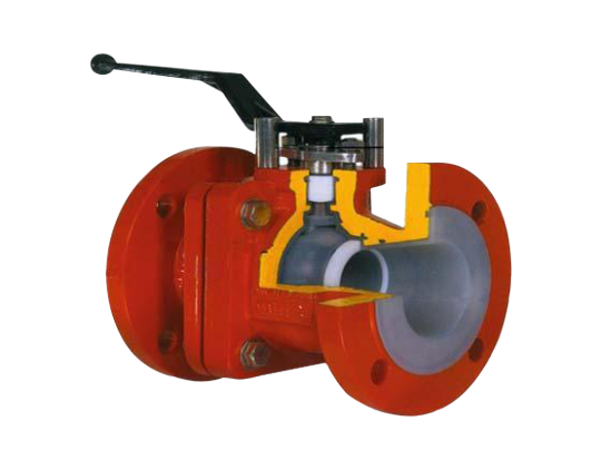
Aira 4Matic Global Valve Automation Pvt. Ltd. is a reliable name in this field for good quality PTFE lined ball valves. It is essential that the functioning of these valves is proper, or else it might meddle with the production of the unit. A valve is an opening or parting that allows liquid or gases to pass through it. This valve moves in a rapid to and fro motion when liquid moves through it. It imitates the fluttering of the wings of a PTFE lined ball valves and hence, is known as a PTFE lined ball valves
Advantages Of PTFE lined ball valves
These valves are very precise and are very handy when it comes to the functioning of the plant. These valves make it easier for liquids to pass through them at a moderate speed. It increases the productivity of the machines and ensures that the result is correct according to the standard. You can prevent overflow of the fluid inside by using the valve in the proper manner. If there is an internal overflow, it will ruin the entire production process.
Also, suppose you produce strong chemicals that might be corrosive. In that case, you need to be extra careful while handling it. Using improved machinery will help you avoid unfortunate accidents. It will safeguard the lives of the workers, prevent you from facing legal complications, and uphold the reputation of your company.
These valves are very easy to use because you can fix or open them easily without much hassle. Therefore, it speeds up the process as there is no prolonged installation time. Moreover, it does not require a lot of materials to build it; hence, it is not very costly. It is a relief for investors to knows that such parts are readily available and that too at an affordable price.
In comparison to other valves, these take up much less space and therefore, the fitting is superior. That accentuates the performance of the machine and improve the quality of production. Machines or parts should make it easier for plants and correct minor human errors. Hence, being aware of such innovative parts and using them entirely for the benefits industry is wise.
To Sum It Up
There are multiple concerns of any industry. The labour depends on it, and so does other smaller factories and suppliers. Hence, if there is a problem in the production unit, it wrecks the demand and supply chain. Therefore, you have to be very careful while using machine parts. Choose a reliable company to purchase such parts so that you have a smooth and quality experience.
Aira 4Matic Global Valve is an ISO 9001:2015 company, manufacturers and exporter of PTFE lined plug valves in India. Company’s manufacturing unit is established in Ahmedabad. We are offering PFA lined butterfly valves, PTFE lined ball valves and weir diaphragm valves.
0 notes
Text
Uses of Valves
Some custom valves are not industry specific; they can be used across a wide range of industries, including chemical processing, food and beverage, gas transmission, mining, oil and gas, and power generation.
Some are dedicated to fluid power applications, including solenoid, poppet, hydraulic, cartridge, and air logic valves. Others are for general pipeline applications or smaller-scale fluid systems and include plug, piston, pinch, globe, gate, disc, diaphragm, butterfly, and ball valves. Then there are valves designed to activate automatically in certain events including relief valves and check valves.
Some valves are so common that they are grouped by function, for example, boiler feedwater and blowdown control valves, faucet valves, float valves, double block and bleed valves, HVAC zone valves, or floor drain check valves. Some valves are so specialized that they may have only one or two applications, such as rotary solenoid valves used in excavators, or inverted vent check valves used in sewage systems and on ships.
As for pipeline valves, many can be thought of as suited either to blocking or throttling. A ball valve is better suited for on-off applications than it is for regulating flow. The same goes for gate and piston valves. For flow regulating, globe and butterfly valves are preferred choices, with globe valves being especially common. Ball valves can be designed so that friction loss through an open valve is no greater than what would be encountered in a like diameter pipe (also making them piggable in some cases). Other valve types usually introduce some loss in the valve owing to the need to place the components of the valve, actuating shafts, etc. directly in the stream and/or the need to redirect the direction of fluid flow.
Most pipeline valves are available with manual levers or handwheels which can be adapted to gear type actuators in larger sizes and fitted with electric or electro-pneumatic actuators for automatic control. Valves fitted with such actuators are sometimes called control or flow control valves in that with automatic actuation they can be integrated into control loops used for process automation. The phrase “control valve” is sometimes used to describe the valves used in hydraulic and pneumatic fluid power systems to actuate a ram, for example. Any valve can be a control valve, that is to say.
Any valves fitted with automatic actuators could be considered control valves, as they presumably would be tied in with remote process controllers. The same valve without the actuators would still be a globe valve, gate valve, etc. albeit one with manual control via handwheel or lever. Many control valves retain some form of manual control by which the valve can be opened and closed. Some valves are considered control valves if they have mechanical means of sensing flow rate, pressure, etc. and can adjust the valve through pilots, for example. In the smaller sizes, solenoid valves function as control valves. Many manufacturers will provide integrated valve and actuator combinations, for example, motorized ball valves.
Valve material can play an important role in valve selection especially when it comes to handling aggressive fluids, abrasive slurries, food products, and so on. Material concerns address not only the wetted parts but can extend to the materials of the valve body too. For instance, valves used for food processing need to resist caustic washdown chemicals and usually demand stainless steel even for exterior parts that do not contact the product. Some valves are lined to improve their resistance to corrosive fluids, etc. Check valves are sometimes lined with PTFE for improved operation and wear resistance. Valves are available in the smaller sizes in a host of plastics and find use in many laboratory applications. Ball valves, for example, are available in brass, stainless steel, polypropylene, and other plastics. So-called sanitary valves are fitted with quick disconnect flanges so that they can be removed from the pipeline easily for internal sanitizing, and are especially popular in the ball, butterfly, and plug designs. The valves themselves often have features which enable quick disassembly and reassembly. Two popular valve styles which use no contacting metal parts in the fluid are the diaphragm and the pinch valves.
0 notes
Text
Safety Relief, Pressure Relief & Reducing Valve Manufacturer India
We Manufacture, Supply & Export our Pressure & Safety Relief Valve, Pressure Reducing & Safety Valve in India & many other countries
safety valve
automatic control valve
thermal relief valve
safety valve
PTFE Lined Pressure Relief Valve
pressure reducing valve
pressure regulating valve

#safety valve#automatic control valve#thermal relief valve#PTFE Lined Pressure Relief Valve#pressure reducing valve
0 notes
Link
Valves Types
July 3, 2017
P.Eng.
Meena Rezkallah
Dear engineers, If you are searching for "Valves" or "Valves Types" the article below present all the information about valves types, installation and operation.
Read Valves Types Part 2
Gate Valves
Gate valves are primarily designed to serve as isolation valves. In service, these valves generally are either fully open or fully closed. When fully open, the fluid or gas flows through the valve in a straight line with very little resistance. Gate valves should not be used in the regulation or throttling of flow because accurate control is not possible. Furthermore, high-flow velocity in partially opened valves may cause erosion of the discs and seating surfaces. Vibration may also result in chattering of the partially opened valve disc. An exception to the above are specially designed gate valves that are used for low-velocity throttling; for example, guillotine gate valves for pulp stock.
Advantages of Gate Valves
They have good shutoff characteristics.
They are bidirectional.
The pressure loss through the valve is minimal.
Disadvantages of Gate Valves
The following are some of the disadvantages of gate valves that must be considered when selecting a gate valve for an application:
Gate valves are not quick opening or closing valves. Full-stem travel to open or close a gate valve requires many turns of its handwheel or an actuator.
Gate valves require large space envelope for installation, operation, and maintenance.
The slow movement of the disc near the full-closed position results in high-fluid velocities, causing scoring of seating surfaces, referred to as wire drawing. It also causes galling of sliding parts.
Some designs of gate valves are susceptible to thermal or pressure binding, depending upon the application.
In systems experiencing high-temperature fluctuations, wedge-gate valves may have excessive leakage past the seats due to changes in the angular relationship between the wedge and the valve seats caused by piping loads on the valve ends.
Repair or machining of valve seats in place is difficult.
Construction of a Gate Valve
Gate valves consist of three major components: body, bonnet, and trim. The body is generally connected to the piping by means of flanged, screwed, or welded connections. The bonnet, containing the moving parts, is joined to the body, generally with bolts, to permit cleaning and maintenance. The valve trim consists of the stem, the gate, the wedge, or disc, and the seat rings.
Two basic types of gate valves are the manufactured-wedge type and the double-disc type, and there are several variations within each of these types. A third type of gate valve, called conduit valve, is shown in Fig. A10.5.
Wedge Type
There are four types of wedges: solid, hollow, split, and flexible wedge. The solid wedge is a single-piece solid construction. It does not compensate for changes in seat alignment due to pipe end loads or thermal fluctuations. As such it is most susceptible to leakage. Except for NPS 2 (DN 50) and smaller, solid-wedge discs are generally not recommended for use in applications having temperatures in excess of 250°F (121°C). Solid-wedge gate valves are considered the most economical. Almost all small, NPS 2 (DN 50) and smaller, gate valves are solid-wedge gate valves. Solid-wedge gate valves are generally used in moderate to lower pressure-temperature applications. It is common practice to use cast iron or ductile iron solid-wedge gate valves in cold or ambient water lines. A hollow wedge is a variation of solid wedge with the exception of a hole in the center. The hollow wedge travels along the stem when the threaded stem isrotated, thus opening or closing the valve port.
The flexible wedge is also one-piece construction like a solid wedge, but areas behind the seating surfaces are hollowed out to provide flexibility. This construction compensates for changes in seat alignment for improved seating while maintaining the strength of a solid wedge in the middle. This design offers better leaktightness and improved performance in situations with potential for thermal binding.
The split wedge consists of two-piece construction which seats between the tapered seats in the valve body. The two pieces of split wedge seat flat against the valve seats as the stem is moved downward, and they move away from the valve seats when the stem is pulled upward.
In the wedge or disc-wedge types either a tapered solid or tapered split wedge is used. In the rising stem valves (Fig. A10.1), the operating threads are out of direct contact with the fluid or gas. The nonrising stem type (Fig. A10.2) is preferred where space is limited and where the fluid passing through the valve will not corrode or erode the threads or leave deposits on the threads. Also, the nonrising stem valve is preferred for buried service.
When the valve is closed, the gate disc is wedged on both sides against the seat. In split-wedge gate valves (Fig. A10.6), the two-piece wedge disc is seated between matching tapered seats in the body. This type is preferred where the body seats might be distorted due to pipeline strain.
In the rising-stem type of valve, the upper part of the stem is threaded and a nut is fastened solidly to the handwheel and held in the yoke by thrust collars. As the handwheel is turned, the stem moves up or down. In the nonrising stem valve, the lower end of the stem is threaded and screws into the disc, vertical motion of the stem being restrained by a thrust collar. The rising-stem valve requires a greater amount of space when opened. However, it is generally preferred because the position of the stem indicates at once whether the valve is open or closed. Nonrising stem valves are some times provided with an indicator for this purpose.
Double-Disc Type
In the double-disc parallel-seat valves (Figs. A10.7a, A10.7b, and A10.7c), the discs are forced against the valve seats by a wedging mechanism as the stem is tightened. Some double-disc parallel- seat valves employ a design which depends mainly upon the fluid pressure exerted against one side of the disc or the other for its tightness. The major advantage of this type is that the disc cannot be jammed into the body, an action that might make it difficult to open the valve. This is particularly important where motors are used for opening and closing the valve.
Unlike the wedge in a wedge-gate valve, which only comes into contact with the seat rings when the valve is nearly closed, each disc in the parallel-seat valve slides against its seat while the valve is being opened or closed. Consequently, these components must be made of metals, which do not gall or tear when in sliding contact with each other. The double-disc parallel-seat gate valve is often favored for high-temperature steam service because it is less likely to stick in the closed position as a result of change in temperature.
Conduit Gate Valve
It is also referred to as a slide valve or parallel slide. The disc surfaces are always in contact with the body seats. Like the double-disc or parallel-seated gate valve, its disc seats against the downstream seat, depending on the flow direction. The inside diameter of a conduit gate valve is equal to the inside diameter of the connecting pipe. These valves are used in pipelines where pigs are run through the piping to perform cleaning of builtup deposits or debris. The typical applications of conduit valves include dirty river water with suspended solids or water with sludge or debris.
Conduit gate valves require a large-space envelope because of their longer disc proportions to accommodate both the blank and the spacer halves of the disc assembly. The valve is closed by moving the blank half downward to block the valve port. The spacer is accommodated in the sump part of the valve body. Refer to Fig. A10.5.
Conduit valves with Teflon (PTFE) seats can be used for low to intermediate temperatures (to 450°F or 232°C). Metal-seated valves may be used for temperatures up to 1000°F (538°C).
Thermal Binding
Thermal binding occurs when a valve is tightly shut off while the high temperature system is in operation. Later when the system is shut down and allowed to cool, thermal contraction of the valve seats move inward more than the wedge shrinkage. This can bind the wedge and seats tight enough to not allow the wedge to unseat or move when the handwheel or the valve actuator is activated to open the valve. Parallel seated gate valves are most suitable for applications having potential for thermal binding. Split-wedge or flexible-wedge type gate valves are expected to perform better than solid-wedge gate valves when thermal binding is a concern.
Pressure Binding
Sometimes in high-temperature applications, the flow medium, such as water or steam, is trapped in the valve bonnet area when the valve is closed for system shutdown. The valves that do not permit this trapped liquid or the condensate to reenter the piping either upstream or downstream may experience excessive pressures in the bonnet cavity when the system returns to operating temperature. This built-up pressure in the bonnet cavity can prevent the valve from opening and may cause damage to valve parts. See Fig. A10.8a.
Pressure binding may not occur if the leakage past the upstream seat is adequate to prevent over pressurization of the valve bonnet cavity. The following options offer solutions to this problem:
Drill a small hole on the upstream side of the disc. See Fig. A10.8b.
Install a small manual stop valve between the valve bonnet-neck and the upstream end of the valve. This valve shall be opened during startup.
Install a small relief valve in the bonnet.
Edward valves offer a new valve called ACEVE to solve this problem.
Typical Gate Valve Applications
Socket or butt-welding end-gate valves in air, fuel gas, feedwater, steam, lube oil, and other systems are typical applications. Threaded-end gate valves may be used in air, gaseous, or liquid systems. Con-cern for leakage from threaded connection can be addressed by seal welding the threaded connection or by using thread sealants, as appropriate. In low-pressure and low-temperature systems such as fire protection systems’ water piping or water distribution pipelines, flanged gate valves are commonly used.
Globe Valves
Conventional globe valves may be used for isolation and throttling services. Although these valves exhibit slightly higher pressure drops than straight- through valves (e.g., gate, plug, ball, etc.), they may be used where the pressure drop through the valve is not a controlling factor. Also, wye-pattern (Fig. A10.9) and angle-pattern (Fig. A10.10) globe valves exhibit improved flow characteristics over the tee-pattern (Fig.
A10.11) globe valve. Because the entire system pressure exerted on the disc is transferred to the valve stem, the practical size limit for these valves is NPS 12 (DN 300). Globe valves larger than NPS 12 (DN 300) are an exception rather than the rule. Larger valves would require that enormous forces be exerted on the stem to open or close the valve under pressure. Globe valves in sizes up to NPS 48 (DN 1200) have been manufactured and used.
Globe valves are extensively employed to control flow. The range of flow control, pressure drop, and duty must be considered in the design of the valve to avert premature failure and to assure satisfactory service. Valves subjected to high-differential pressure-throttling service require specially designed valve trim. Generally the maximum differential pressure across the valve disc should not exceed 20 percent of the maximum upstream pressure or 200 psi (1380 kPa), whichever is less. Valves with special trim may be designed for applications exceeding these differential pressure limits.
Types of Globe Valves
Tee Pattern globe valves have the lowest coefficient of flow and higher pressure drop. They are used in severe throttling services, such as in bypass lines around a control valve. Tee-pattern globe valves may also be used in applications where pressure drop is not a concern and throttling is required. Refer to Fig. A10.11.
Wye Pattern globe valves, among globe valves, offer the least resistance to flow. They can be cracked open for long periods without severe erosion. They are extensively used for throttling during seasonal or startup operations. They can be rod through to remove debris when used in drain lines that are normally closed. Refer to Fig. A10.9.
Angle Pattern globe valves turns the flow direction by 90 degrees without the use of an elbow and one extra weld. They have a slightly lower coefficient of flow than wye-pattern globe valves. They are used in applications that have periods of pulsating flow because of their capability to handle the slugging effect of this type of flow. Refer to Fig. A10.10.
Construction of a Globe Valve
A typical large globe valve with flanged ends is illustrated in Fig. A10.11, and a large wye-pattern globe is illustrated in Fig. A10.9. Globe valves usually have rising stems, and the larger sizes are of the outside screw-and-yoke construction. Components of the globe valve are similar to those of the gate valve. This type of valve has seats in a plane parallel or inclined to the line of flow.
Maintenance of globe valves is relatively easy, as the discs and seats are readily refurbished or replaced. This makes globe valves particularly suitable for services which require frequent valve maintenance. Where valves are operated manually, the shorter disc travel offers advantages in saving operator time, especially if the valves are adjusted frequently.
The principal variation in globe-valve design is in the types of discs employed. Plug-type discs have a long, tapered configuration with a wide bearing surface. This type of seat provides maximum resistance to the erosive action of the fluid stream. In the composition disc, the disc has a flat face that is pressed against the seat opening like a cap. This type of seat arrangement is not as suitable for high differential pressure throttling.
The conventional disc, in contrast to the plug type, provides a thin contact between the taper of the conventional seat and the face of the disc. This narrow contact area tends to break down hard deposits that may form on the seats and facilitates pressure-tight closure. This arrangement allows for good seating and moderate throttling.
In cast-iron globe valves, disc and seat rings are usually made of bronze. In steel-globe valves for temperature up to 750°F (399°C), the trim is generally made of stainless steel and so provides resistance to seizing and galling. The mating faces are normally heat-treated to obtain differential hardness values. Other trim materials, including cobalt-based alloys, are also used.
The seating surface is ground to ensure full-bearing surface contact when the valve is closed. For lower pressure classes, alignment is maintained by a long disc locknut. For higher pressures, disc guides are cast into the valve body. The disc turns freely on the stem to prevent galling of the disc face and seat ring. The stem bears against a hardened thrust plate, eliminating galling of the stem and disc at the point of contact.
Advantages of a Globe Valve
The following summarizes the advantages of globe valves:
Good shutoff capability
Moderate to good throttling capability
Shorter stroke (compared to a gate valve)
Available in tee, wye, and angle patterns, each offering unique capabilities
Easy to machine or resurface the seats
With disc not attached to the stem, valve can be used as a stop-check valve.
Disadvantages of a Globe Valve
The following are some shortcomings inherent in globe valves:
Higher pressure drop (compared to a gate valve)
Requires greater force or a larger actuator to seat the valve (with pressure under the seat)
Throttling flow under the seat and shutoff flow over the seat
Typical Applications of Globe Valves
The following are some of the typical applications of globe valves:
Cooling water systems where flow needs to be regulated
Fuel oil system where flow is regulated and leak tightness is of importance.
High-point vents and low-point drains when leak tightness and safety are major considerations.
Feed water, chemical feed, condenser air extraction, and extraction drain systems.
Boiler vents and drains, main steam vents and drains, and heater drains.
Turbine seals and drains.
Turbine lube oil system and others.
Needle Valves
Needle valves generally are used for instrument, gauge, and meter line service. Very accurate throttling is possible with needle valves and, therefore, they are extensively used in applications that involve high pressures and/or high temperatures. In needle valves (Fig. A10.12), the end of the stem is needle point.
Check Valves
Check valves are designed to pass flow in one direction with minimum resistance and to prevent reverse or back flow with minimal leakage. The principal types of check valves used are the tee-pattern lift check, the swing check, the tilting-disc check, the wye-pattern lift check, and the ball check, illustrated in Figs. A10.13 to A10.17, respectively.
Construction of a Check Valve
A basic check valve consists of a valve body, bonnet or cover, and a disc which is attached to a hinge and swings away from the valve seat to allow fluid to flow in the forward direction, as in a swing or tilting-disc check valve, and returns to valve seat when upstream flow is stopped. Thus, reverse flow is prevented. In folding- disc check valves, the disc consists of two halves attached in the middle.
The two halves fold backward when upstream flow is initiated. Activated by a spring, the two halves quickly close the flow path when upstream flow ceases. In the case of lift-check valves, the disc is in the form of a piston which is moved out of the flow path by upstream flow and returns to the valve seat by gravity to stop back flow. Ball-check valves have a disc in the form of a ball.Check valves are available in sizes from NPS ¹⁄₄ (DN 6) through NPS 72 (DN 1800). Other sizes may be made available to meet specific size requirements. Depending upon the design requirements of a piping system, a check valve may have butt welding, socket welding, threaded, or flanged ends.
Advantages of Check Valves
They are self-actuated and require no external means to actuate the valve either to open or close. They are fast acting.
Disadvantages of Check Valves
The following are some of the disadvantages that are attributed to check valves:
Since all moving parts are enclosed, it is difficult to determine whether the valve is open or closed. Furthermore, the condition of internal parts cannot be assessed.
Each type of check valve has limitations on its installation configurations.
Valve disc can stick in open position.
Types of Check Valves
There are several types of check valves having varying body configurations. The following are some commonly used types of check valves:
Swing Check Valve. In swing check valves, the disc is unguided when it moves to fully open position or to fully closed position. Many different disc and seat designs are available to satisfy requirements of varying applications. Soft-seated– swing check valves provide improved leak tightness compared to metal-to- metal seating surfaces. Combination seats consisting of a metal seat ring with resilient insert also offer better leak tight characteristics. The seating angle, the angle between the seat and the vertical plane, may vary from 0 to 45 degrees. Vertical seats have a 0° angle. Larger seat angles reduce the disc travel, resulting in quick closing, thus minimizing the possibility of water hammer. Usually the seat angles are in the range of 5 to 7 degrees.
Lift Check Valve. Lift check valves are particularly adapted for high-pressure service where velocity of flow is high. In lift check valves, the piston disc is accurately guided by long contact and a close sliding fit with the perfectly centered dash pot. The walls of the piston and dash pot are of approximately equal thickness. Large steam jackets are located outside of the dash pot and inside the piston to eliminate sticking because of differential expansion. The seat ring is of a barrel- type design of heavy uniform cross-section. It is normally screwed in and seal welded. The flow opening is full port size. Refer to Figs. A10.13 and A10.16. The seat design of a lift-check valve is similar to a globe valve. The disc is usually in the form of a piston or a ball. The ball-lift check valves are used in highly viscous fluid service. These valves have superior leaktight characteristics to those of swing- check valves. The piston type lift check valves have a tendency to stick in the open position when service fluid has sediment trapped above the piston. Large lift check valves are furnished with an equalizer line between the chamber above the disc and the downstream side of the valve.
Tilting Disc Check Valve. The tilting-disc check valve is designed to overcome some of the weaknesses inherent in conventional swing check valves. A combination of design features enables the valve to open fully and remain steady at lower flow velocities and to close quickly upon cessation of forward flow. The dome-shaped disc floats in the flow with fluid on both bottom and top of its surfaces, thus it has minimum dashpot effect. It performs well in pulsating, turbulent, and high-velocity flows. These attributes prolong the valve’s lift and reduce flow-induced dynamic loads on the piping system. Refer to Fig. A10.15.
Folding Disc Check Valves. This valve is also referred to as double-disc or split- disc check valve. Refer to Fig. A10.18. It is manufactured in wafer-body pattern and is available with soft or hard seats. It is very popular in low-pressure liquid and gaseous services. Its lightweight compact construction makes it a preferable check valve when space and convenience are important.
Vertical or In-Line Check Valve. These valves are available in two configurations: in-line ball check and fully guided disc with soft or hard seats. In-line ball check valves can be used in both vertical and horizontal lines. The fully guided disc inline check valves must be provided with a spring-assist closure when used in horizontal lines. In vertical lines, the guided disc in-line check valves may or may not be provided with spring-assist closure. The spring-assist closure not only assists in closing the valve quickly, it minimizes the possibility of water hammer by preventing flow reversal. They can be used in applications having pulsating flows, such as in a discharge line of a reciprocating compressor. Because they are compact in size, they are ideal for application in tight spaces.
Stop Check Valve. A stop check valve can either be used as a unidirectional check valve or as an isolation (stop) valve like a gate or globe valve. During normal operation of a system, these valves are used as a regular check valve; however, when needed, these valves can be closed with the help of a screw-down stem which is not fastened to the valve disc. The stem, when fully screwed down, holds the free-floating disc against the valve seat, just as in a gate or a globe valve. These valves are available in tee-pattern, wye-pattern, angle-pattern, and inclined pattern. The swing-and-piston lift-disc design check valves are commonly used as stop check valves. Refer to Figs. A10.19a and A10.19b.
Application Considerations
The force of gravity plays an important role in the functioning of a check valve and, therefore, the location and orientation of the check valve must always be given consideration. Lift and ball check valves must always be placed so that the direction of lift is vertical. Swing checks must be located to ensure that the disc will always be closed freely and positively by gravity.
The flow velocity of the fluid through the valve has a significant effect on the life of the check valve. The valve should be sized such that the fluid velocity under normal conditions is sufficient to keep the disc fully open and pressed against the stop. This minimizes disc fluttering, which is the primary cause of valve failure.
Also, a check valve should not be located immediately downstream of a source of turbulence, such as a pump, elbow, control valve, or a tee-branch connection. It is recommended that manufacturer’s recommendations be followed to provide the required straight run of pipe upstream of the check valve. Some manufacturers recommend 8-to-10 pipe-diameter length of straight run of pipe upstream of the valve. Sometimes, the layout and the space available may not allow compliance to manufacturer’s recommendations. Alternatives must be evaluated and the most reasonable and feasible approach be implemented. A swing check valve may be used in the vertical run of a pipe only when the flow is upward. In addition, the flow velocity and the fluid pressure must be adequate to overcome the disc weight and swing it to the fully open position. In-line ball check valves are suitable for application in horizontal or vertical lines.When the flow is suspected to be pulsating and low, use of a swing check valve is not recommended. Due to the continuous flapping of the swing disc against the seat, valves suffer considerable damage, and at times the swing discs can come loose. Table A10.9 summarizes preliminary application guidelines for selection of a suitable type of check valve. The user must evaluate specific application featuresto determine the right valve for the application.
Typical Applications of Check Valves.
Table A10.9 provides a brief summary of different types of check valves and their typical applications. The preliminary guidelines of this table may be used to determine the suitable check valve for an application, considering the specifics of the application. #Little P.Eng
Engineering Consultant Services
TAGS:
Valves Types
0 notes
Text
Types of Borosilicate Glass Process Equipment in India
Looking for high quality borosilicate glass process equipment in India? Here is your answer! Ablaze Glass Works is a well-known borosilicate glass manufacturer in India offering glass process equipment for three decades now. For mass industrial supply to single piece, every order is catered with 100% commitment at Ablaze Glass Works. In this blog post, lets learn about Borosilicate Glass Process Equipment by Ablaze Glass Works that are ranked best in the market:
Valves
Ablaze Glass Works manufactures and delivers valves made of Borosilicate glass 3.3. Valves are available with PTFE bellow. These borosilicate valves are widely used in the chemical and pharmaceutical industries. Valves are further categorized based on overflow, monitor line flow and so on.
Vessels and Stirrers
Vessels by Ablaze Glass Works can be used as borosilicate glass reactors, glass vessel chemical reactors, receivers, separators and re-boilers. Vessels can also be used for measurement, storage and feed. They also manufacture many kinds of stirrers that usually comprise two parts namely a drive unit and stirrer shaft.
Pipeline and Column Component
Borosilicate glass pipeline components of Ablaze Glass Works have smooth surfaces, universal resistance, and transparency permit and can be easily cleaned. There is no risk of contamination in these pipeline column components among process equipment. Ablaze Glass Works also manufactures column components and its accessories in its process equipment segment.
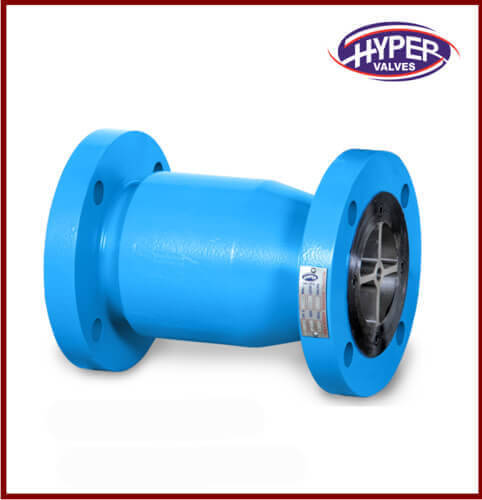
Pressure Relief Valve
Pressure Relief Valves aim to protect reactors and thereby prevent accidents. These open automatically when system pressure exceeds pre-set value without any electrical power or control from outside. Pressure relief valves by Ablaze Glass Works are heat and corrosion resistant. Glass Pressure Relief Valves are part of process equipment in India.
If you need any or mass supply for borosilicate glass process equipment in India, contact Ablaze Glass Works now. Ablaze Glass Works has many more kinds of borosilicate glass process equipment listed on their website.
0 notes
Link
PTFE Lined Safety Relief Valves offer over pressure protection for unfired pressure vessels and plant systems used with corrosive and high purity liquids, gases and vapors.
0 notes
Text
Pressure Regulator vs. Pressure Control Valve: What's the Difference?
PTFE Lined Pressure Relief Valve regulates fluid flow by opening or closing a valve in response to an electrical signal created by a process variable (temperature, pressure, or level). The process directly controls a regulator.
A pressure regulator, for example, does not require external power to operate; instead, pressure from the fluid on the diaphragm activates the open/close action of the valves.
If the pressure in the pipeline is equal to or slightly below the set point pressure, the PCV will open an output valve to let hydrocarbons. Maintaining a safe transit pressure and correct metering of the item are both aided by automating fluid control in this manner.

Although they operate differently, both a pressure relief valve (PRV) and a pressure control valve (PCV) are used to control pressure.
A PCV is the first line of defense in an oil field, preventing hydrocarbons from flowing through a channel under pressure. A PRV is a static secondary safety device used to 'bleed out' excess pressure from a pressurized system or an oil and gas well.
Pressure Relief Valve vs. Pressure Regulator
A pressure regulator differs from a pressure relief valve in several ways. A pressure regulator, like a PCV, is primary safety equipment used in oil and gas facilities to control pressure. On the other hand, a PRV is a secondary safety device that controls secondary (non-critical) pressure.
Safety Valve for Pressure (PSV)
A pressure safety valveis an instinctive safety device that immediately relieves pressure on a squeezable fluid vessel to prevent critical failure and death from over pressurized vessel conditions.
What is the difference between PCV and PSV?
In terms of function, a PSV and a PCV are very similar. The fundamental difference between a PSV and a PCV is that a PSV's valves open almost wholly when the fluid reaches the setpoint temperature. A PCV's valves open gradually.
Choosing the Correct Control Instrument – Response Time
Pressure regulating valve have a faster reaction time than pressure control valves because they are process-controlled and do not require an intermediate relay system for control.
Continuity between DCS, sensors, and actuators is required for PCVs. As a result, when one component fails, the entire system is vulnerable to instrumentation failure.
0 notes