#Pin header connector Push Wire Connector
Explore tagged Tumblr posts
Visit Tumblr Blog
Explore Tumblr blogs with no restrictions, modern design and the best experience.
Last Seen Tumblr Blogs


Fun Fact
The “We are the 99%” Tumblr blog became the slogan for the Occupy Wall Street movement.
Text
https://www.futureelectronics.com/p/interconnect--connectors-rectangular-plastic-industrial/873-902-ve00-5000-wago-7970049
Connectors, Headers and Wire Housings, 873-902/VE00-5000, WA
Yellow 2 Pole Push Wire Connector for Luminaire Disconnect
#Connectors#Headers and Wire Housings#873-902/VE00-5000#WAGO#Electrical wire connectors push-in#connector#Plug Housing#Pin header connector Push Wire Connector#board to board connector#pin header socket#Female pin header#crimp
1 note
·
View note
Text
Wire cable assembly, Plug Housing, pin header cable, push-in wire connectors
2 Position Rectangular Housing Connector Plug Gray
0 notes
Text
"Why Wire-to-Board Connectors Matter in Today's Tech Landscape"
In the ever-evolving landscape of electronics and electrical engineering, wire-to-board (WTB) connectors are fundamental components that provide a secure, efficient link between a set of discrete wires and a printed circuit board (PCB). Despite their small size, these connectors are indispensable in a wide range of applications—from consumer electronics and automotive systems to industrial machinery and telecommunications.Get more news about Wire-to-board Connector,you can vist our website!
What Are Wire-to-Board Connectors? Wire-to-board connectors are used to route electrical signals or power from individual wires onto a printed circuit board. Unlike board-to-board connectors that facilitate connections between PCBs or wire-to-wire connectors that link individual wire sets, WTB connectors interface directly between a cable harness and the board, typically through soldering or press-fit terminals. This facilitates modular design, ease of maintenance, and scalable manufacturing.
They consist of two primary components: the plug (housing the wires) and the receptacle or header (mounted on the PCB). These connectors are available in various pitches (the center-to-center spacing between pins) and configurations (vertical or right-angle orientations), making them adaptable for a variety of design constraints and spatial limitations.
Key Features and Considerations Designers and engineers often evaluate several critical factors when selecting WTB connectors:
Current and Voltage Ratings: Depending on the application, connectors must meet safety and performance thresholds.
Pitch Size: Fine-pitch connectors (≤1 mm) allow for compact design, while larger pitches offer greater robustness.
Locking Mechanisms: Latch or friction locks ensure secure connections that resist vibration or accidental disconnection.
Material and Plating: Contact materials, often copper alloys with gold or tin plating, influence conductivity and longevity.
Environmental Resilience: Some WTB connectors are designed for harsh environments with resistance to moisture, dust, or high temperature.
Applications Across Industries The versatility of wire-to-board connectors is reflected in their widespread use across diverse industries:
Consumer Electronics: Used in smartphones, laptops, and wearable devices for internal signal and power connections.
Automotive: Essential for infotainment systems, sensors, and electronic control units (ECUs), where compact, vibration-resistant connectors are critical.
Medical Equipment: Connectors must meet stringent reliability and safety standards in devices like diagnostic equipment and patient monitors.
Industrial Automation: WTB connectors facilitate modular assembly and simplify maintenance for sensors, controllers, and interface devices.
Trends and Innovations Modern trends push the boundaries of connector miniaturization and performance. As electronic devices become more compact and sophisticated, the demand for high-density connectors with increased signal integrity and EMI shielding continues to grow. Additionally, some manufacturers are integrating features like surface-mount technology (SMT) compatibility and automated cable termination to streamline production and assembly.
Another key trend is the development of eco-friendly, RoHS-compliant connectors to meet global environmental standards while ensuring high performance. With the rise of Industry 4.0 and the Internet of Things (IoT), wire-to-board connectors are playing an increasingly strategic role in enabling smart, connected systems.
Conclusion Although often overlooked compared to high-profile semiconductors or processors, wire-to-board connectors are vital enablers of modern electronic innovation. Their reliability, precision, and adaptability allow designers to build smaller, more powerful, and more efficient systems. As technology continues to advance, the humble WTB connector will remain a quiet but essential hero in the background—connecting ideas to reality, one circuit at a time.
0 notes
Text
https://www.futureelectronics.com/p/interconnect--pin-and-socket-connectors--header-plug-wire-mount/873-953-ve00-0500-wago-8000714
WAGO, 873-953/VE00-0500, Connectors, Pin and Socket, Connectors Plug Housings
873 Series 6 A 3 Position Push Wire Luminaire Disconnect Connector
#WAGO#873-953/VE00-0500#Connectors#Pin and Socket#Connectors Plug Housings#Crimp terminals#Header plugs#board-mount connector#socket plug#plug and socket#Male plug#socket#right angle electrical plug adapter#Newark#Plug adapter outdoor
1 note
·
View note
Text
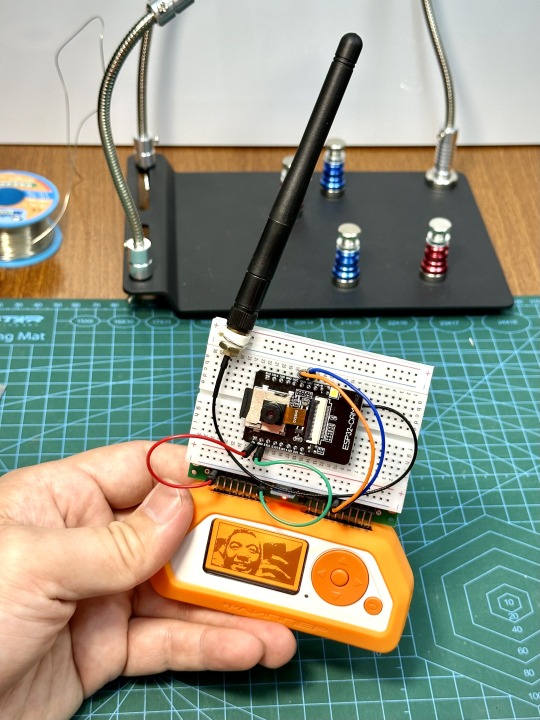
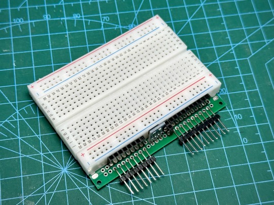
DIY: Flipper Zero Quick Prototype Module
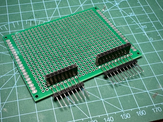
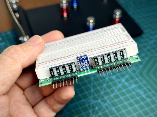
Tinkering with Flipper Zero and adding various modules have been fun, but I found doing it with breadboard and jumper wires have been rather messy and it's difficult to bring the add-on around with wires and components hanging off the Flipper Zero. So, I decided to spend a couple of hours to put together a quick prototype module with breadboard attached that plugs into Flipper Zero. I also added an AMS1117 5v to 3.3v step down power supply buck to the board, so that 3.3v also comes from the 5v pin. This makes the module hot pluggable as long as you don't use the Flipper Zero's 3.3v pin. It's a lot more convenient this way. Here's the final result! What do you think?
Now I can try out quick builds of various projects and bring it around to test it with no issue, before committing to a design and making it permanent. Here are more examples using this quick prototype module.
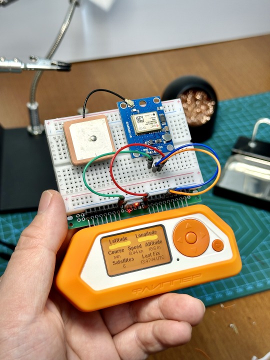

It just cost me a few bucks for the parts and I think it's time well spent. If you wish to make one yourself, here's a quick guide below.
Build Steps
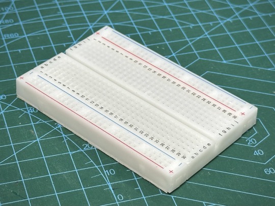
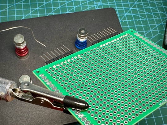
Here are the stuff you will need for this project: An 8cm x 6cm double sided prototype board, a 400 hole breadboard, some 25mm male and female header pins, some jumper wires and an AMS1117 5v to 3.3v step down power supply buck. These can be found in Aliexpress, Amazon, Lazada, etc.

First, cut away the connectors on the side of the breadboard just to give it a cleaner look.

Next is to cut the female header pins to the right length, or you can just get the right sizes of the shelf. You need one with 8 pins and another one with 10 pins.

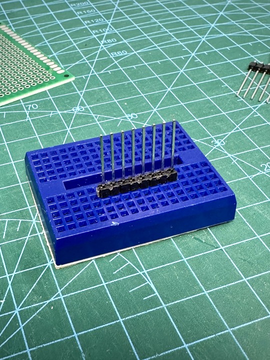
Next, we need to cut the male header pins to length. Again, we need one with 8 pins and one with 10 pins. After that, stick the header pins all the way into a breadboard, then use a ruler/screwdriver to slowly push the plastic thingy holding the pins down until it touches the breadboard.

Use a masking tape to mark the pin at 5mm above the plastic thingy. This is the line where you will bend the pins.

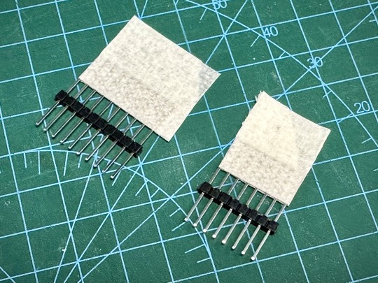
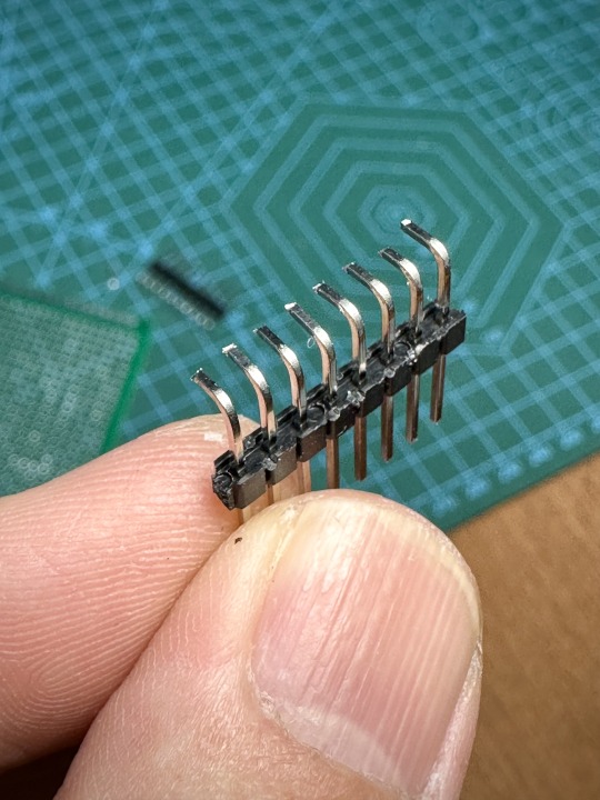
Now use a plier to bend the pins 90 degrees, then cut the pins shorter like below. You can cut the pins after soldering it on to the board, but I find it easier to cut it before.


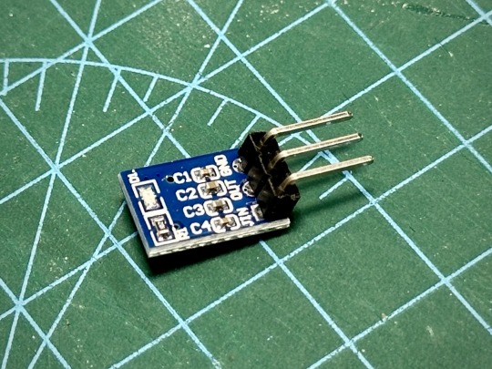
Next, we work on the power supply step down module. You need to remove the plastic thingy from the pins. Just use a cutter to trim it off, then bend the pins straight.

Now you can solder the male header pins to the prototype board like below. You can also see how the female header pins should be placed on the board.
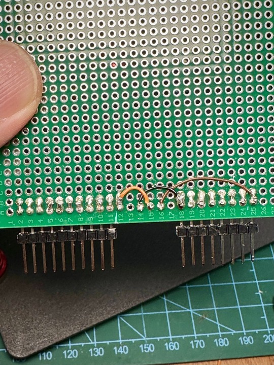
Bend the legs of the female header pins so that they lean towards the solder points of the male header pins, then solder each corresponding pin to bridge them together.

Now go ahead and also solder the power supply module and wire them accordingly. Note that I also cut a 2 pin female header and I wired both to the 3.3V VOUT from the power supply module.
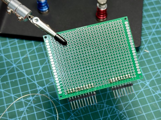
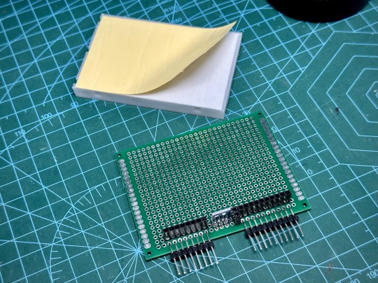
At this point, it's probably good to take out the multimeter (or use the continuity tester app on Flipper) to test all the connections to make sure all the connections are good and that there are no shorts. After that, peel off the tape backing from the breadboard and stick it on the module.
That's it! You're done, and now you have a nifty quick prototyping module for your Flipper Zero that will make your experimenting a lot more enjoyable.

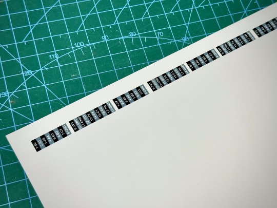
Oh, and just one more thing ... I designed and printed some stickers to label the pins on the module. This makes it a lot less likely that you will stick the connections in the wrong holes. You can download the PDF for the stickers here.
There, now we are really done. Let me know what you think, or how I can improve this. Have fun!
0 notes
Text
Plug wire, Socket Plug connectors, pin and socket connectors, pin headers
873 Series 6 A 3 Position Push Wire Luminaire Disconnect Connector
#WAGO#873-953/VE00-0500#Connectors#Pin and Socket Connectors#Plug Housings#Header plugs#Pin headers#PCB sockets#power connector pins#header contains#Interconnect#Pin Terminal Connector#plug wire#Socket Plug connectors
1 note
·
View note
Note
Hi! It's not something you've talked about in a long time, but do you have any tips for building a pc? My laptop is on its final legs and I'm just gonna upgrade.
I'm using pcpartpicker to make sure everything is compatible and I'm learning what I need for what I'll be using it for, but I'd love some tips if you have any!
the manual that will come with your motherboard will be very thorough and will make it easy to understand where things go, as long as you read it diligently. use youtube guides extensively for anything that is not clear to you, there are hundreds available. just make sure you find one relevant to the brands you're using (don't use a guide for an Intel build if you are building AMD, for example). the front panel connectors are the one thing i always need to look up.
as far as compatibility goes, you said you're using PCParts, but be aware that your CPU and RAM are the largest compatibility concern, as they go hand-in-hand with your motherboard. if you want the latest generation of tech for any one of those three, you have to commit to all three, as there is no backwards compatibility with older generations.* keep this in mind as you consider your price vs. performance options. the older generations are less expensive and still perform very well, but when they will eventually need replacing, if you intend to move to a newer gen (as you may have to unless you scour for secondhand old gen stuff), you will have to replace multiple components, which is expensive and also requires gutting your entire PC. every PC owner who does their own builds faces needing to do these upgrades at some point, it's just a question of how far down the road you want it to be.
if you are pushing on something hard and it's not going into the socket, double and triple check yourself. the sockets are firm but they do not require herculean strength. if something isn't going in, there is a high chance it's not supposed to go there. if you're certain it's the right wire for the socket, make sure you have the orientation correct. a lot of the headers have a specific number of pins in a specific orientation, if you try to put a wire in upside down, it will not go in and pushing too hard will bend or break the pin on the board.
get a fully modular power supply. just trust me on this.
do not touch the pins on your CPU. reference the CPU manual to be very certain you have the orientation correct before you attempt to place it. if you break a pin you are shit out of luck.
for pins on the motherboard, if you bend them by accident you can VERY GENTLY straighten them with tweezers.
do all of your work on a wooden table or hardwood floor, do not work on a carpeted/fabric surface, this will increase the likelihood of introducing static to the components, which can damage or break them. touch something metal to discharge any static before touching your PC parts. some people insist on wearing anti-static bracelets but you don't have to as long as you're careful.
have fun! building a PC is pretty straightforward once you get into it. it's more like putting a puzzle together than anything else, except at the end you have a cool machine and other people will think you're some sort of tech genius.
*some motherboards have backwards compatibility with DDR4 RAM but not all of them, and none of them have compatibility with old gen CPUs.
#Anonymous#PC building#i'm sure there are other things i could say but nothing else comes to mind at the moment
29 notes
·
View notes
Text


This 1965 Ford Mustang fastback (Chassis 5T09A146475) is built for spirited road performance with a Terlingua paint scheme found much less often than the Shelby stripes commonly seen on modified fastbacks. The build sheet is impressive, with a dyno-tuned 302, Tremec 5-speed, 4-wheel disk brakes, Cobra Automotive suspension, and a stiffened unibody. The original A-code 289 and 4-speed transmission are included (needing rebuild), and the car is a turn-key driver with a aged patina that makes it perfect for road events
This car was originally delivered to the state of Florida and discovered in North Carolina wearing its original time-faded body panels and interior. The seller says that the car is amazingly fun to drive, partially because there is no power steering, power brakes, A/C, or radio. We had the same list in our ’65 fastback, and so did the ’65 Shelby cars before they were softened in ’66, and wouldn’t do otherwise if we have one again. Mechanical enhancements from Cobra Automotive are as follows: ■Big spindle kit w/larger bearings (as per the Trans Am cars) ■Billet aluminum racing hub kit ■Deep Trans-Am lug nuts ■Rollerized coil spring pivots ■Road race coil springs (600 lb. with polyurethane spring insulators) ■Koni adjustable shock absorbers w/Koni urethane bushings kit ■Competition front cross member (used on the Boss 302 Trans Am cars) ■Super duty tie rod end kit ■Quick steer kit w/frame pin and rollerized bearing kit w/idler arm pitman arm ■Competition master cylinder upgrade with stainless steel brake lines ■Adjustable brake proportioning valve ■Competition front & rear disc brakes ■Adjustable brake push rod ■Roller bearing steering kit ■Stage 1 Road Race Rear Suspension ■Shelby style under ride traction bars ■Lowering blocks (1 inch) ■Competition kill switch (battery) ■Rotunda racing mirrors ■GT 350 hood pin kit; Other upgrades include: ■Control Freak Suspension upper & lower control arm set ■Torque Thrust aluminum wheels ■Sub-frame connectors ■Heavy duty racing clutch ■1-inch competition front sway bar ■Halogen head lights (Tri-bar) ■LED tail lights ■Battery relocation to trunk ■Electrical rewire (Ron Francis Retro kit) ■Headlight wire mesh stone guards;
The engine was built on a 1992 302 roller block and was broken in on the dyno and tested at 300hp and 315 lb-ft of torque. It has 3000 miles since the rebuild at West Carleton Automotive in Ottawa, Canada, and was assembled in the style of the ’65 Shelby GT 350 with black painted block, Cobra valve covers, hi-po 14″ air cleaner assembly, and ceramic coated Tri-Y headers. Other details on the build include: ■Hot tank and mag tested parts ■Sonic inspection on block ■Align hone ■Pedestal rockers ■E303 roller cam ■Roller lifters ■Eagle connecting rods ■Speed Pro pistons ■Speed Pro oil pump and pick-up ■Clevite cam bearing set ■ARP fasteners ■True roller timing set ■MSD electronic distributor ■140 amp heavy duty alternator ■Heavy duty fuel pump ■K & N air filter ■Competition high capacity oil pan ■4 core aluminum radiator w/ electric fan ■Dual exhaust with Shelby type glass pack mufflers matching revs. There is also an alarm and kill switch installed
The car still features the original seats, headliner, and door panels, and is fully original apart from the new original style carpet and one arm rest. The fold-down rear seat remains intact and a quality wood steering wheel from Tony D. Branda has been added. The dash has the R-model instrument panel with AutoMeter tach, speedo, fuel, water temp, amp., oil pressure, and volts gauges, as well as a competition oil pressure warning light. The ’65 Shelby radio block-off plate means the driver gets to concentrate on matching revs. There is also an alarm and kill switch installed.
#1965 ford mustang#ford mustang#fordperformance#muscle car#classic cars#fastback mustang#pony car#american muscle
12 notes
·
View notes
Text
Nucleo f401re clion

#NUCLEO F401RE CLION CODE#
#NUCLEO F401RE CLION SERIES#
#NUCLEO F401RE CLION FREE#
PC0, PC1, PC2, PC3, PC10, PC11, PC12, PC13, PC14, PC15Ĭan be used to power them module from battery They are also categorized with the table below: The name of the pins can be found in the image above. They comprise of GPIO pins, Analog Pins, Timer Pins, and Power pins. These pins are classified into CN7 and CN10 with each having 38 Pins. These pins can also be used for I2C Communication A4 is SDA and A5 is SCLĬan be used to provide analog reference voltageĪcts as SCK, MISO, MOSI and CS pins respectively for SPI communicationĪcts as Rx and Tx pins respectively for USART communicationĪpart from the Arduino pins, the board also has 76 (38+38) GPIO pins as male headers on either side of the board as shown above. Provides 3.3V as output can also be used to power the MCU Each category pin can be tabulated as follows: The Arduino pins are split into category CN5, CN6, CN8, and CN9. The arduino like pins are female connector pins which exactly match the order and position of Arduino UNO pins and hence any Arduino shield can be used with these development boards. The pin one resembles the Arduino UNO and the blue one is the STM32 style ( Morpho). As you can see, there are two sets of pins. The STM32 Nucleo board pinout is shown above. The Board operates with 3.3V supply but a wide voltage range of 7-12V can be provided to the VIN pin since it has an on-board voltage regulator. Similarly, there are two push buttons where one is user programmable, and the other is to reset the Microcontroller. This board also comes with an integrated ST-LINK/V2-1 programmer and debugger hence it is very easy to get started with this board.Īs shown in the image above, there are three LEDs, where LD1 is for indicating USB communication, LD2 is programmable LED, and LD3 indicates power. The Boards pinout is similar to Arduino UNO and has many other additional pins to expand performance. It features the ARM Cortex M4 32-bit STM32F401RET6 microcontroller which is in LQFP64 package. Errors and Warnings List: The left pane shows the list of errors and warnings and some hints are provided inside the code.The STM32 Nucleo boards are the official Development Boards from STMicroelectronics.
#NUCLEO F401RE CLION CODE#
The code is checked as you type, with suggestions, help and error checking. Check-as-You-Type Code Control: This is really amazing.
#NUCLEO F401RE CLION SERIES#
ATmega-based Trinket boards from Adafruit, - Atmel ATmega- and Cortex-M3 SAM-based boards from Arduino, - Microchip PIC32-based chipKIT boards from Diligent, - Atmel ATmega328 with BLE BLuno board from DFRobot, - Atmel ATtiny85-based board from Digistump, - Intel Quark SoC X1000-based Galileo boards from Intel, - LaunchPad MSP430 and LaunchPad Cortex-M4 Tiva C series boards from Texas Instrument, - ARM Cortex-M3 STM32 F103RB-based board from Maple, - ATmel ATmega328 and ATmega644-based boards from Microduino, - ARM Cortex-M4 Freescale MK20-based Teensy 3.0 and 3.1 from PJRC, - Atmel ATmega644p-based board from Wiring, - Nordic nRF51822 SoC-based boards from RedBearLab, - Nucleo F401RE on mbed from STMicroelectronics, - Freedom KL25Z on mbed from FreescaleĬode Presentation: Syntax colouring, line numbering and function highlighting ease code reading.
#NUCLEO F401RE CLION FREE#
It eases development for the most popular embedded computing boards.Īfter having played with embedded computing platforms for a while, I was looking for one single IDE and a better one.īecause I'm a Mac user, I designed embedXcode, a template for Xcode, the free and standard IDE on Mac.ĮmbedXcode supports the most popular boards based on the Wiring / Arduino framework and on the mbed framework.
1 note
·
View note
Text
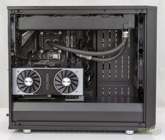
Fractal Design Meshify S2 Black Tempered Glass Edition


Fractal is launching the new version of the Meshify case line which is all about airflow, the Fractal Design Meshify S2. Fractal tends to build a more subdued case. Lacking from Fractal's line up are RGB LED-laden chassis. Don't get me wrong, there's a time and a place for RGB LEDs. Fractal has taken lessons learned from their other lines and has incorporated those features in the Meshify S2. With airflow over aesthetics being the priority for the series, it is easy to see why it is quite popular with enthusiasts and overclockers alike. The Meshify takes what was good about the original design and attempts to improve on it. Technical Specifications Meshify S2 Black Tempered Glass Edition Model Name FD-CA-MESH-S2-BKO-TGL Front Panel Color Black Dimensions (mm) L538 x W233 x H455mm Material Steel, Metal Mesh, ABS, Tempered Glass M/B Type EATX (up to 285mm wide), ATX, mATX, ITX Front Ports 1 x USB 3.1 Gen 2 Type-C 2 x USB 3.0 Audio I/O Drive Bays 5.25″ 0 3.5″ 2 (Convertible to 2.5″ bay) 2.5″ 5 (2 x Converted from 3.5” bays) Expansion Slots 7 + 2 vertical Fan Slots Front 3 x 120/140mm (2 x Dynamic X2 GP-14 included) Rear 1 x 120/140mm (1 x Dynamic X2 GP-14 included) Top 3 x 120/140mm Bottom 2 x 120/140mm Radiator Support Front 120/240/360mm Rear 120mm Top 120/240/360mm 140/280/420mm (max 35 mm MB component height) Bottom 120/240mm 140/280mm PSU max length 300mm Maximum Compatibility VGA Card Length: Max 440mm with front fans mounted CPU Cooler Height (From M/B to side panel): 185mm Cable routing space 23mm Packaging The Meshify S2 ships in a thick cardboard box. On the front of the box is a line art depiction of the case as well as the color indicator. Black and White are available at launch. On the rear, an exploded view is available. The sides of the box list the additional features. Internally, the Meshify S2 is protected from damage during shipping as it is capped with large pieces of Styrofoam. A thin plastic bag covers the case underneath the Styrofoam to protect the case's finish from scuffs and scrapes.

The installation kit is tucked away in one of the 3.5" drive bays on the back of the case. Fractal includes enough screws, zip ties, hard drive dampeners, and other accessories to get your system installed in the case. A user guide and warranty instructions are also included. A Closer Look At The Meshify S2 The most prominent feature on the "business" side of the case is the tempered glass panel. The sample that I received has a light tint to it making the interior of the case clearly visible. From the factory, the glass, as well as a handful of other parts, are covered with a light plastic film that gives a satisfying feeling when removed.

The front of the case features the Meshify's signature angular mesh panel. The panel can be removed to clean the foam behind it. To remove the mesh panel, you'll need to reach under the lip of the front bezel and press upwards on the catch that releases the mesh panel. There is a layer of foam behind the mesh with acts to absorb sound as well as trap dust, although I'm not sure trapping dust was intended. Either way, it is easy to take off, clean, and reassemble. The front of the case can support a 360mm radiator with a maximum width of 147mm. Moving up to the top of the Meshify, you'll find the front panel I/O as well as the power and reset buttons. The front I/O include two USB 3.1 Gen-2 ports, a single USB type C, and 3.5mm audio jacks for headphones and microphone.

The top of the Meshify is, well, mesh. This mesh panel pops up by using a button on the rear of the case to release the plastic catches. The panel can be removed to get easy access to the cooling bracket underneath. The cooling bracket is removable as well. This allows you to install radiators or fans outside of the case and grants easy access to the top of the motherboard. Once the components are in place on the bracket, simply secure it back in place. The top cooling bracket also features a dedicated fill port allowing you to fill your loop without opening the side panels of the case.

On the rear of the case, the power supply is mounted at the bottom of the case. An adapter is included to aid in the installation. 7 horizontal expansion slots, as well as two verticle slots, are available for use. A single 120mm fan is also present on the rear of the case.

Taking a look at the bottom of the case, a removable full-length dust filter held in place by four brackets between the case feet. The chrome plastic case feet have thin rubber pads to keep the Meshify S2 from sliding around the desk. Internally, the Meshify S2 is wide open. Front to back, the case measures 465mm without the front fans installed and 440mm with. The motherboard tray features a large cutout that gives access to the back of the CPU socket when installing a backplate for CPU coolers. The front section of the case features verticle slots, these are the reservoir mounts. Fractal as also included reservoir brackets to aid in mounting. Rubber grommets are in place at each opening where wires would pass from the component area of the case to the backside of the motherboard tray. Fractal includes three of their Dynamic X2 GP-14 140mm fans. These fans push air at 68.4 CFM at a sound level of 18.9 dBA.

A full-length power supply shroud runs from the font to the back of the case. Not only does this allow you to hide wires and preserve a clean looking case, but the shroud also provides alternate mounting locations for 2.5" drives as well as serves as the mounting location for the vertical GPU mount. For those that prefer large reservoirs, the front panel of the shroud can be removed. Looking at the top of the case, you can see the removable cooling bracket. This bracket supports a 420mm radiator with a maximum thickness of 35mm

A Closer Look Continued The backside of the motherboard tray features two 2.5" mounting locations and three 3.5" drive cages. Access to the power supply connectors is provided by a cutout that runs roughly 1/2 the length of the case.

The two 2.5" drive mounts can be removed from the back of the motherboard tray and mounted to the top of the power supply shroud. The three 3.5" drive trays are completely removable when not in use. The design allows them to mount behind the reservoir with little to no interference. The drive trays will also accept 2.5" drives as well. In order to help tidy up cabling, Fractal as included a SATA power extension for 3.5"/2.5" drives installed in these locations.

The Nexus+ PWM fan hub is mounted to the backside of the motherboard tray. The input for the hub comes from the motherboard's PWM header and is powered by a SATA connector. The hub can support three PWM fans as well as six 3-pin fans.

To get the installation started, I chose to start with the power supply. Simply remove the mounting bracket from the back of the case, screw it to the power supply and slide it into place.

Next up I installed the motherboard. All was well and good until I installed the CPU cooler. The cooler I chose to use for this build is EKWB's Predator AIO. The cooler uses 120mm fans, however, as I attempted to install the cooler more towards the center line of the case, the motherboards VRM heatsinks prevented this. Thankfully there are multiple mounting points for 120mm and 140mm fans and radiators.

The rest of the installation went smoothly. Cable routing was made a bit easier as there is ample space behind the motherboard tray. I did find my self wanting longer fan cables to route to the PWM hub, however, an extension fixes this issue. The back side of the case features two velcro strips to help secure cables. Fractal included plenty of zip tie locations, 14 as a matter of fact, to help manage the cables.

The front side of the case came out pretty clean as well. I chose to use the vertical mount GPU as well as mounted the SSD to the power supply shroud.
Conclusion and Final Thoughts Putting together a system inside the Meshify S2 was fairly painless. As I mentioned before, I did find myself wanting a little longer cables to the front fans from the Nexus PWM fan hub. An extension did solve this issue and would allow most of the cables to run as a single bundle. That is except for the USB Type-C cable. Depending on the location on your motherboard, it may be a challenge. The pass-through for the motherboard tray and the power supply shroud do a lot to help hide wires and keep things nice and tidy. There's plenty of space for me to get my meat hooks in and out of the case without too much of a challenge. No sharp edges exist inside as I was able to put our system together unscathed.

The cooling performance of the Fractal Design Meshify S2 was perfectly acceptable. I've spent a bit of time with the case over the last couple of weeks and the stock i7-8700K didn't see temperatures in excess of 60°C and the Nvidia RTX 2080TI reached 78°C during heavy gaming sessions. Even during those sessions, the fans were still quiet. The Nexus+ PWM Fan hub was connected to the motherboards CPU_OPT fan header and set to normal in the BIOS. Good airflow through the case helped keep fan noise and temperatures in check. The Fractal Design Meshify S2 shares its core with another Fractal Design, the Define S2. And why not? Is this bad. For me, I say no. If the design works, then use it. By using the same core, Fractal can produce the cases at a lower cost in both design time and manufacturing. The differences between the two series, the Define series caters to aesthetics more so than airflow whereas the Meshify's focus is on airflow. Granted, in my opinion, the Meshify S2 with its angular front panel looks just as good. I personally have used the Define S2 and like it just fine. Each has their own place. The MSRP for the tempered glass versions will run you $149.99 and the non-glass version will set you back $139.99. Read the full article
0 notes
Photo

Couple of days ago a little fire broke out in my enclosure. Since I got a bit careless during the intense prototyping of the new hotend design and constant coupling and decoupling of the liquid carrying tubes, some liquid leaked in the enclosure causing me to clean that and I forgot to safely redock two current carrying pins which shorted out and set the inside on fire. Luckily I was next to it when it happened because it could have ended a lot worse. In short it was stupid to use current carrying pins with male headers to begin with. And taking the fire alarm out because the prototype was blowing smoke, was fine but it should always return inside afterwards. ____________________________ Two push connectors upstream of the short melted acting as fuses, which happened weeks ago but only when it wasn't desirable on my hotend wiring. So those connectors aren't 10A rated by my experience, I wouldn't trust them above ~1A. ____________________________ Short term I fixed the safety issue and I will add inline fuses at strategic points and added an thermal fuse to the hotend wiring. Long term I will add an fire alarm which I will trigger to somehow call me, and or text me or something. #3dprinter #safety #fire #prevention #electronics #Rotterdam #nultien https://www.instagram.com/p/Bs0Iue2ntlw/?utm_source=ig_tumblr_share&igshid=13lgvunlszcgf
0 notes
Text
They are in games, decorations, shadow boxes, sign borders, torches, spotlights, and so on…
This slideshow requires JavaScript.
Making a Lightshow
Using an Arduino Nano on an expansion board with a push-button to change the color palette mode of the RGB LED strip. A microphone module is used to detect sound and alter the speed of flashing lights.
Why Arduino?
The greatest advantage to using the Arduino family of microcontrollers for these types of projects, is that they are ubiquitous. Since they are so available, they are inexpensive and you can find open-source software to get started. If you’ve ever had the opportunity to work with an Arduino Uno microcontroller board, then you’ve probably executed the flashing LED example. Going further, you might attach a button, or switch, to trigger the LED or to turn it off making the project interactive.
There are many sensors that could be connected to the Arduino Uno and setup to trigger events, such as the LED flashing, using threshold values that we would need to experiment with in order to figure out what settings work best for creating the effect we want.
While the examples that come with the Arduino software and the examples included with libraries are an excellent start to a project; the Arduino family of microcontrollers is often grossly underutilized in many projects. Sure microcontrollers are limited in how many instructions it can run and hitting the program size limit doesn’t take very long when you want to control more than a few blinking LEDs.
Even with creative variable handling and custom libraries, eventually, there is a need for another microcontroller or to move to a larger one. In my hydroMazing Smart Garden System and in my Alien Invasion Slot Machine projects, I push the Arduino closer to its limits.
Time Management and state and trigger flags
At its most basic, a microcontroller loops through a set of instructions handling each action with the focus of The Red Eye of Sauron from Lord of the Rings. There are a few interrupts that can be configured should an event be so important to receive the full attention of the microcontroller. Using some form of time management creates a state machine. If x amount of time has passed since x event, then do something and so on…
“The behavior of state machines can be observed in many devices in modern society that perform a predetermined sequence of actions depending on a sequence of events with which they are presented. Simple examples are vending machines, which dispense products when the proper combination of coins is deposited, elevators, whose sequence of stops is determined by the floors requested by riders, traffic lights, which change sequence when cars are waiting, and combination locks, which require the input of combination numbers in the proper order.” https://en.wikipedia.org/wiki/Finite-state_machine
There are rare instances where: RTOS, AI, neural networks exist on microcontrollers, but that’s best left to software-oriented systems such as a Raspberry Pi.
After trying many different timer and time management libraries I felt they were either too much or not enough of what I was wanting in my timers. A set of timers that are easy to set, keep track of their own state, and each have their own trigger flags.
Button assumptions
Interacting with an electronics device such as a microcontroller or computer system is relatively easy and typically provided as an example for developers looking to use the device in their project. Press a button and an LED illuminates. A button or switch may seem like a simple sensor input, but it’s not.
The device’s system resources are consumed waiting and watching for a button press. When we use a button in a project we typically think of it being activated when pressed. Then what? What should happen if the user holds the button in the active position? Will the button be counted as pressed once, or is the program going to count each second, or x amount of time, as another button press? Does the program need to know that the button has been released?
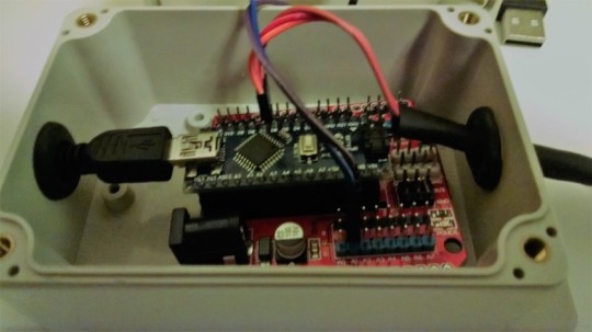
Hardware
I’m going to be adding on a lot of peripheral devices and moving away from basic prototyping. Rather than using the Arduino Uno and a protoboard or breadboard for this project, I’m using the Arduino Nano on an expansion board. I’ve created several color palettes by porting the sample code from the FastLED library examples to my base code templates. with a push-button input to change the color palette mode of the RGB LED strip.
Wiring
Keep it simple using common wiring colors, keep it modular so connections can be made with ease, keep your project sustainable; a part can be replaced rather than the entire system. The DuPont wire connectors that come with prototyping starter kits makes it easy to create your own custom wiring connections. The wires are easy to solder when a more permanent connection is needed. I make custom wiring harnesses for neater, cleaner, and more easily connectable modules.
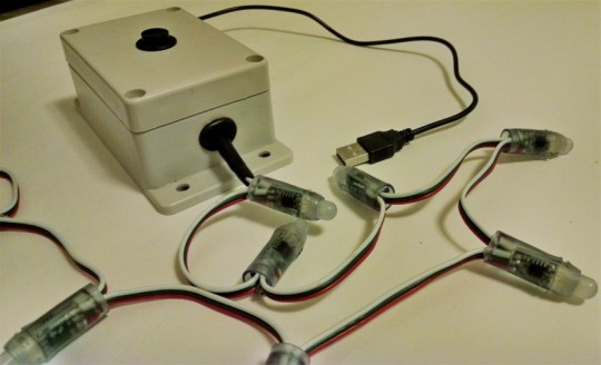
Lighting Effects
There many RGB LED options, so I will be focusing on the WS2811/WS2812 modules. Single RGB LEDs to strings of RGB LEDs in various configurations. Most of the RGB options will have three wires for connecting to the microcontroller board and require 5vdc or 12vdc. Unless you are designing a new printed circuit board, use DC/DC conversion modules to convert your power to the needs of your project. You might need to step-up voltage from 3v to 5v, or maybe step-down 12v to 5v?
*** The more lights added, the more power needed. ***
The Arduino Uno, and variants, should only be used for directly powering peripheral modules and not devices. Consider the maximum current consumption when determining what is a device and what is a module. A string of lights is more of a device as opposed to a panel indicator light, motor controller boards are modules, not the motors they drive, MOSFET boards, not the valves or solenoids that they control.
Common Options for Power
USB Powered Devices
AC/DC wall-wart Power Supplies
Rechargeable Batteries
Solar Panels
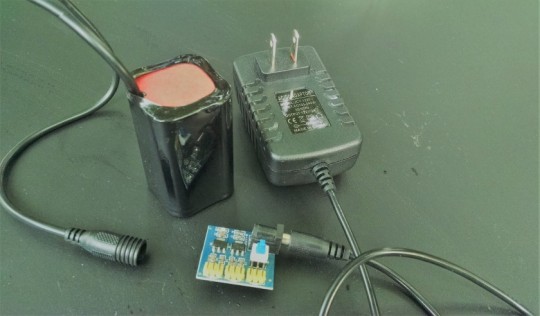
Parts:
Arduino Nano
Expansion Board
USB to mini USB cord
AC/DC Outlet Power Adapter
Project Box
(1-4) strips of 10 RGB 12mm LEDs.
(1) push-buttons
microphone
Steps:
Insert Arduino Nano into the Expansion Board by carefully pressing the Nano pins into the expansion boards headers. Note the picture where only half of the pins are correctly inserted. Plan to provide power using USB to mini USB cord. Optionally, AC/DC Outlet Power Adapter.
Prepare the following wiring connections to the expansion board by soldering and protecting with heat-shrink:
(1-4) strips of 10 RGB 12mm LEDs.
(1) push-button
microphone
Programming considerations:
brightness of lights
color palette
speed of flashing lights
what triggers change?
Connect the push-button to the expansion board.
Connect strip(s) of 10 RGB 12mm LEDs to the expansion board and upload test code.
Optionally, connect the potentiometer to the expansion board and upload test code.
Making projects more interactive
Every sensor gives us a data-point to work with, providing an input so that our program can make a decision based on its current environment or what happens when conditions are met. Going further with the project, I’ve added a microphone to detect sound, and at a later time, I’ll add a PIR sensor to detect motion.
Connect the microphone to the expansion board and upload test code.
Complete the project with an enclosure.
Drill 7/16” – 1/2” holes into the project box:
HOLE 1: side ~ USB to mini USB cord ~ Optionally, AC/DC Outlet Power Adapter
HOLE 2: cover ~ push-button
HOLE 3: side ~ 1-4 x strips of 10 RGB 12mm LEDs
It takes time to learn how to use tools and equipment successfully, let alone, have the time to actually make the project meet your expectations. Time used for the project is time that could be spent with family, friends, learning something more important, etc.
You can purchase a completed Lightshow directly from me as a functioning example.
Making a Lightshow with Arduino They are in games, decorations, shadow boxes, sign borders, torches, spotlights, and so on... Making a Lightshow…
#arduino#crafts#DIY#electronics#expansion board#how-to#interactive#led#making#nano#RGB#uno#WS2811#WS2812
0 notes
Text
Bringing the Tail to a Con (and a few hardware changes)
As I’m sure most regular readers know by now, I was was planning to take my tail to Furnal Equinox. It was a mad rush to get everything done and a few major modifications to the electronics were made, but I’m happy to say that my tail made it to FE.
With a week to go before FE, it very quickly became apparent that my original board was not going to work. I didn’t have time to make a wireless remote for it and it was far too large to fit into my pocket.

The original controller design was huge! It was very nearly 30mm tall without including the battery pack that has to go on the back in order to power everything. There was no way it was going to fit into my pocket. I could have easily made it fit with a custom PCB and surface mount components, but with FE less than a week away, I certainly didn’t have the time to do that.
It was clear that I had to redesign the electronics to fit using parts that I had available.

I quickly got to work designing and etching a new board that I was confident would fit in my pocket. The new board didn’t include a wireless transceiver, but it was small and included four buttons.

This board is based around an Arduino pro mini clone I had sitting around. The pro mini includes an on-board 3.3v regulator and a couple of LEDs, so I didn’t need to add much hardware besides the buttons and a few passives. After assembling the board, I got to quickly porting my code to the new platform. This was actually fairly straight forward as I wrote wrappers around most low level hardware specific functions. I was able to get things working again on the new board in just a couple of hours.
With the new board working, I designed an enclosure for it. I went through quite a few iterations of this enclosure before I was satisfied. I had originally intended to put the battery pack on the back as before, but this made the enclosure too big once again. I later decided to put the battery pack on my belt beside the tail after a friend suggested it.

The controller tucks easily into my pocket, while the batteries stay on my belt (the small piece of electrical tape was added to prevent things like loose change from getting inside the enclosure or shorting the programming header). The battery pack has a simple belt loop screwed into it.
Unfortunately, I ran into issues getting the connectors for the battery pack that I wanted in time and ended up using automotive spade terminals.

These seem to work well in this application as they have excellent vibration resistance and can handle the required current easily. Unfortunately, one of my connectors had a bad crimp and I didn’t realize it until unpacking my tail. It ended up breaking immediately upon removing it from my bag and I wasn’t able to fix it immediately as I had forgotten some of my tools.
Fortunately, I’m not the only furry into electronics and making things and after asking around, I was able to borrow a pair of pliers and temporarily fix it. I forced a pin from one of my buttons through the connector to “uncrimp” it and widen it enough to get the wire back through it. I then recrimped it around the wire. This worked but unsurprisingly, the crimp didn’t really hold too well and I was forced to push the wire back in a few times.
I was able to keep the tail working for the entire con, however. I had a lot of fun using it, and I got to talk to a lot of furries about animatronics and electronics!
I’ll be taking a short break from this project to work on something else but the next step for this project will be working on reducing the noise from the servo. It is pretty difficult to notice in the noisy public con space, but It seems that a few people heard the tail before noticing it was moving.
3 notes
·
View notes
Text
Lian Li’s new UNI FAN SL120 fans have been something we’ve been anxious to get our hands on since CES 2020 where we had a chance to check out early prototypes. RGB fans are a dime a dozen these days, so it takes something special to stand out from the crowd. Lian Li does this with the UNI FAN SL120’s with a rather ingenious way to connect them together. While there have been a few daisy-chainable fans, and even a single frame 120 x 360mm triple fan from Cooler Master recently, Lian Li has a very unique approach. The new UNI Fans lock together to allow up to four fans to be used as a single device with a single set of cables. The power and lighting signals are passed along to the next fan in line without the need of short daisy-chain cables. Each UNI FAN runs up to 1900 RPM, pushing over 58CFM of air with a water-cooling friendly 2.54mm H2O of static pressure. Each fan includes 32LED’s in two mirrored groups down each side. If that isn’t enough, the included controller independently handles up to 4 groups of fans. For those counting, that’s up to 16 fans with a staggering 512 LEDs and over 900CFM supported by a single controller.
PC Test Bench would like to thank Lian Li for sending us over a UNI FAN 3 pack with the controller to check out!
Lian Li’s take on the UNI FAN: The all-new UNI FAN SL120 is an addressable RGB fan which features daisy-chaining, thus saving users’ neck by eliminating the need for unnecessary cable management. Together, the customizable RGB lighting shining through the high-static pressure fans and the L-Connect Software provides quick access to fan speed and lighting effect control, making your dream build more accessible than ever.
Features
Daisy-Chain Design for Unprecedented Flexibility
The daisy-chain structure ensures a pain-free installation process by eliminating the need to unclutter your PC from all the pesky cables. By simply interconnecting the UNI FANs together, users can easily create a cluster of up to 4 fans and control its RPM, colors, brightness, and lighting effects in one go. Compared to most fans on the market that come with at least two cables per fan, it takes only one cable module for 4 UNI FANs to receive power and signals, allowing users to create a neat and clean internal configuration effortlessly.
A Designated UNI FAN Controller to Easily Manage 16 Fans in One Go
The included UNI FAN controller contains 4 designated UNI FAN ports. Each port can connect to a cluster of 4 UNI FANs via the cable module, allowing users to control up to 16 UNI FANs in one go. Together, the cable module and controller help reduce cable clutter and provide for an organized and well-managed connectivity, which lets the user easily create a minimalistic design focused on aesthetics and simplicity.
L-Connect Software for Intuitive Fan Control
The L-Connect software enables users to control and adjust fan RPM, colors, brightness, and lighting effects with extreme ease. The clean and straightforward layout of the L-Connect interface enables users to intuitively control either a single cluster of UNI FANs or all 4 clusters in one go. By dragging the toggle located on the top right, users can also create a synchronized system by passing over the control of the fans to the motherboard software.
EXTREME COOLING CAPABILITY
The UNI FAN SL120 is a high-static pressure fan that can effectively force the heat to dissipate through the tight fin spacing of high-density radiators. With a maximum fan speed of 1900 RPM and the ability to operate silently at full speed, efficient thermal management can be achieved effortlessly
Maximum Static Pressure: 2.54 mm H2O Maximum Fan Speed: 1900 RPM Maximum Airflow: 58.54 CFM
Industrial-Grade Motor
Each of the high-static pressure fans is propelled by an industrial-grade motor that enables the fans to operate silently at full speed.
Fluid Dynamic Bearing (FDB) Technology
Each high-static pressure fan feature fluid dynamic bearing technology, which provides a thin layer of oily fluid to supports the load of the fan blades to effectively reduce the friction caused by the moving parts in contact with the bearings.
Extra Magnetic Support
Extra magnetic force has been added to the center hub to support the fan blades, reducing the vibration level of each fan and thus ensuring a low noise level while in operation.
SOPHISTICATED RGB LIGHTING
Apart from being capable of delivering sufficient airflow in and out of the system silently, the UNI FAN SL120 is also a quick and easy add-on to adorn your build with vivid RGB lighting. 32 addressable RGB LEDs embedded in each fan (16 LEDs on either side of the frame) ensure brighter and more complex lighting effects.
AVAILABLE IN TWO COLORS
The UNI FAN SL120 is available in black or in white and is scheduled to launch on August 19th at a price tag of US$79.99 for a 3 pack (fan controller included), and US$24.99 for a single pack (fan controller excluded). Without the pesky cables slithering and floating around within the build, building a one-of-a-kind PC is a breeze.
Specifications
Fan Dimension 122.8 X 122.4 X 25mm Rated Voltage DC 12V (FAN) & 5V (LED) Fan Speed 800~1900 RPM Air Pressure 2.54 mmH2O (Maximum) Airflow 58.54 CFM (Maximum) Acoustic Noise 17 ~ 31 dB Locked Current >= 0.5mA Bearing Type Fluid Dynamic Bearing (FDB) Operation Voltage DC 12V & 5V Start-Up Voltage DC 6.0V Input Current 0.18A(FAN) / 0.6A (LED) Input Power 3.5Watt
A Closer Look
#gallery-0-10 { margin: auto; } #gallery-0-10 .gallery-item { float: left; margin-top: 10px; text-align: center; width: 33%; } #gallery-0-10 img { border: 2px solid #cfcfcf; } #gallery-0-10 .gallery-caption { margin-left: 0; } /* see gallery_shortcode() in wp-includes/media.php */
Lian LI’s UNI FAN SL120 fan comes in single fans and 3-packs that include a controller. We have the latter today to check out, in the white variant. Inside the box, each fan is individually wrapped in bubble wrap. You get three sets of screws, some paperwork, one connecting cable, and an accessory box.
Inside the accessory box, we get the controller, another pair of connecting cables so that all 3 fans can be used independently If needed, and some cables. Cables include the SATA power cable that runs the controller, a USB cable and RGB/PWM cable, an addressable RGB splitter, and some mounting pads.
The RGB splitter cable is about 120mm long, the power cable is closer to 300mm and the rest are about 500mm long.
The UNI FAN controller has 4 separate channels available.
Each channel has an RGB connector that locks, releasable by pressing the tab on top, and what appears to be a standard 4-pin PWM fan header. Standard PWM fans can’t easily be connected to unused fan headers as the plastic housing is just a little too tight around the connector.
The top edge has three connectors, a large 4-pin for SATA power input, a smaller 4-pin for USB control, and even a small 3-pin to allow PWM and ARGB signals from your motherboard or another device to be passed along to UNI FANs.
#gallery-0-11 { margin: auto; } #gallery-0-11 .gallery-item { float: left; margin-top: 10px; text-align: center; width: 50%; } #gallery-0-11 img { border: 2px solid #cfcfcf; } #gallery-0-11 .gallery-caption { margin-left: 0; } /* see gallery_shortcode() in wp-includes/media.php */
Lian Li’s UNI FANs utilize a sweeping 7-blade design that promotes high static pressure. Rubber dampers cover each of the 8 corners to minimize vibration and noise. Chrome accents on the center hub and two of the outer edges really make the fan look great when viewed from the side.
The other two edges are more for function and are the secret sauce that makes the UNI FAN unique. One side has male protrusions and a contact pad, and the other has female notches and spring-loaded male contact pins.
The two sides mate together.
You then slide the fans sideways so that the centering marks align and the fans are now connected, not only mechanically but also electrically.
At this point, two more UNI FANs can be added up to a maximum of 4 fans, and the entire assembly is treated as a single device.
Each group of fans gets a single cable adapter than slides onto one side.
#gallery-0-12 { margin: auto; } #gallery-0-12 .gallery-item { float: left; margin-top: 10px; text-align: center; width: 50%; } #gallery-0-12 img { border: 2px solid #cfcfcf; } #gallery-0-12 .gallery-caption { margin-left: 0; } /* see gallery_shortcode() in wp-includes/media.php */
That’s really it. You now have anywhere from one to four fans using a single set of cables. They can be installed for general airflow or mated to radiators like normal or even installed on coolers.
We’ll connectors our kit as one chain to channel one of the controllers and connect power and USB cables. We did experiment with the PWM and ARGB cable to control the fans without software form our motherboard headers, which worked fine but moved back to USB control.
One minor note here is that the power, USB, and control cables all slide fully into the controller. You have no way to disconnect these without pulling on the wiring itself which is a bit of design oversite on Lian Li’s part. This really isn’t recommended, it’s always best for any and all electrical connections to grasp the plug itself and not pull on the wires.
As soon as your power on the UNI FAN system, it jumps to life with a slow rainbow. The lighting is very bright and very rich.
Software & Testing
L-Connect Software
The L-Connect software enables users to control UNI FAN’s and adjust fan RPM, colors, brightness, and lighting effects with extreme ease.
Each of the 4 groups is show here, you click on the group or channel you want to select it, and a green box appears around it. Under LED MODE, you pick how many fans are connected. You can then adjust Lighting effect speed in 25% increments as well as brightness in the same steps. For dynamic lighting modes, you can select which direction the effect travels as well.
Many of the LED mode presets have customizable colors as well. A simulated view of the effect will show on the chosen fan group in the top half of the screen.
The Fan Mode can be changed to a few presets, or manual control. Manual control jumps in 110 RPM Increments from 800-1900 RPM. The live feedback speed will be shown on each group just under the fans.
Static Pressure Testing Our Pressure test rig consists of a sealed PVC box with a 120mm fan hole, and the tested fan is bolted to the cutout over a foam rubber gasket than ensures all pressure the fan can develop is directed into the box and will not leak out around the edges of the fan frame. A pressure port on the side of the box is plumbed to a Dwyer DigiMag Digital Differential Pressure rated +/- 2% accuracy over its full-scale range of 0 to 6.35 mm H2O. This means our accuracy is within +/- 0.127 mm H20 for testing.
Unloaded in free air, the UNI FAN SL120 manages around 1965 RPM and drops to around 1845 RPM dead-headed into our pressure test rig. The UNI FAN’s are rated 2.54 mm H2O but push almost 2.7 at peak. We see a fairly linear drop off with RPM down to around 800 RPM and just over half a millimetre H2O static pressure. Lian Li’s L-connect software steps down in ~110 RPM increments in its 800-1900 RPM range, so we used that stepping for test speeds.
From a noise standpoint, the UNI FAN’s are barely audible at full tilt. Our sound meter goes down to 30 dB and they barely register at full speed at close range so unless you live in an extremely quiet area and are highly sensitive to noise, you likely won’t hear the SL120 fans while in operation.
Final Thoughts & Conclusion
Lian Li’s UNI FAN SL120 is the new one-stop-shop for fans. Providing anything you would want in a fan from solid airflow to high static pressure for superior cooling, all while doing it in style. Oh, and did we mention easy cable management? The highly unique system for joining fans makes building a breeze, and even readily lends itself to a test bench lifestyle where you are constantly changing things around. The fans interlock so firmly, you can hold a full string of 4 fans in place with 2 bolts quite easily. The included controller works really well with the L-Connect software, but we do wish you could remove the main cables without needing to pull on the wiring. A few upgrades down the road, you could find yourself pulling the wires out of the connector accidentally. One thing Lian Li does right here compared to most on the market, the controller remembers your last settings. There is nothing that annoys people (or at least, me) more than getting your lighting just how you like it, and having to deal with generic rainbow puke as you boot up until the software loads. What does near-perfection cost? A single fan is a reasonable $25, but a 3-pack with controller sets you back a fair $80, at the cheapest end of the scale for 3-pack of quality RGB fans.
Overall, Lian Li Really knocked it out of the park with the UNI FAN. The SL120 checks every box, including the all-important price.
Great Job Lian Li!
[sc name=”award-must-have” ]
[sc name=”link_to_same_company_reviews” company=”Lian Li” ]
Lian Li UNI FAN SL120 Fan Review Lian Li’s new UNI FAN SL120 fans have been something we’ve been anxious to get our hands on since CES 2020 where we had a chance to check out early prototypes.
1 note
·
View note
Text
GeeekPi 5V 4A Power Supply & X820 V3.0 2.5″ SATA HDD/SSD Shield Expansion Board Kit for Raspberry Pi 1 Model B+/ 2 Model B / 3 Model B / 3 Model B+
Product Description
X820 V3.zero 2.5″ SATA HDD/SSD Protect with 5V 4A Energy Provide Specification Energy provide: 5Vdc +/-5% , 4A Ports & Connectors: DC jack – 5.5×2.5mm, USB socket – USB 3.zero sort A, Energy output connector – XH2.54 2-pin Energy change connector -PH2.zero 4-pin PCB Dimension 107.5mm x 85mm
Energy Provide Unit AC 100 – 240V enter ~50 / 60Hz, 5Vdc 4A output With 2 snap-in plugs for North America (US) and Europe (EU) DC Energy Plug Dimension : 5.5*2.5mm
Notes To be used with unique energy provide unit solely WARNING: Don’t energy your Raspberry Pi by way of the Pi’s 40-pin header and micro-USB socket on the similar time.
Package deal Contains X820 V3.zero HDD enlargement board x 1 USB Jumper x 1 USB 3.zero A-Male to A-Male Information cable x 1 2-Pin Energy Connection Wire x 1 USB 2.zero A-Male to Micro B Energy Cable x 1 Spacer M2.5 x 12mm x 4 Screw M2.5 x 6mm x 8 Screw M3 x 6mm x 6 Spacer M3 x 15mm x 4 Energy Adapter 5V 4A x 1
Product Options
For Use With Raspberry Pi 1 Mannequin B+/ 2 Mannequin B / Three Mannequin B / Three Mannequin B+
Helps as much as 4TB 2.5-inch SATA arduous disk drives (HDD) / solid-state drive (SSD); Helps USB booting out of your HDD/SSD
On-board push button to regulate energy on /off (Press-ON, Maintain the button pressed not less than 2s -OFF); Powers the Raspberry Pi by way of Pi’s 40-pin header or Micro USB socket
On-board XH2.54 connector and USB energy socket to energy different units; USB 3.1 Gen1 to SATA 6Gb/s bridge controller; USB 2.zero connectivity provides plug-and-play performance in your Raspberry Pi; Fast file switch with high-speed USB 3.zero connectivity from a PC or a Mac; Exterior Self-Powered or USB bus-powered
LED purple indicator signifies powered standing and blue indicator signifies drive standing
The post GeeekPi 5V 4A Power Supply & X820 V3.0 2.5″ SATA HDD/SSD Shield Expansion Board Kit for Raspberry Pi 1 Model B+/ 2 Model B / 3 Model B / 3 Model B+ appeared first on The Ram Memory Store.
The article was originally published here! GeeekPi 5V 4A Power Supply & X820 V3.0 2.5″ SATA HDD/SSD Shield Expansion Board Kit for Raspberry Pi 1 Model B+/ 2 Model B / 3 Model B / 3 Model B+
0 notes
Text
GeeekPi 5V 4A Power Supply & X820 V3.0 2.5″ SATA HDD/SSD Shield Expansion Board Kit for Raspberry Pi 1 Model B+/ 2 Model B / 3 Model B / 3 Model B+
Product Description
X820 V3.zero 2.5″ SATA HDD/SSD Protect with 5V 4A Energy Provide Specification Energy provide: 5Vdc +/-5% , 4A Ports & Connectors: DC jack – 5.5×2.5mm, USB socket – USB 3.zero sort A, Energy output connector – XH2.54 2-pin Energy change connector -PH2.zero 4-pin PCB Dimension 107.5mm x 85mm
Energy Provide Unit AC 100 – 240V enter ~50 / 60Hz, 5Vdc 4A output With 2 snap-in plugs for North America (US) and Europe (EU) DC Energy Plug Dimension : 5.5*2.5mm
Notes To be used with unique energy provide unit solely WARNING: Don’t energy your Raspberry Pi by way of the Pi’s 40-pin header and micro-USB socket on the similar time.
Package deal Contains X820 V3.zero HDD enlargement board x 1 USB Jumper x 1 USB 3.zero A-Male to A-Male Information cable x 1 2-Pin Energy Connection Wire x 1 USB 2.zero A-Male to Micro B Energy Cable x 1 Spacer M2.5 x 12mm x 4 Screw M2.5 x 6mm x 8 Screw M3 x 6mm x 6 Spacer M3 x 15mm x 4 Energy Adapter 5V 4A x 1
Product Options
For Use With Raspberry Pi 1 Mannequin B+/ 2 Mannequin B / Three Mannequin B / Three Mannequin B+
Helps as much as 4TB 2.5-inch SATA arduous disk drives (HDD) / solid-state drive (SSD); Helps USB booting out of your HDD/SSD
On-board push button to regulate energy on /off (Press-ON, Maintain the button pressed not less than 2s -OFF); Powers the Raspberry Pi by way of Pi’s 40-pin header or Micro USB socket
On-board XH2.54 connector and USB energy socket to energy different units; USB 3.1 Gen1 to SATA 6Gb/s bridge controller; USB 2.zero connectivity provides plug-and-play performance in your Raspberry Pi; Fast file switch with high-speed USB 3.zero connectivity from a PC or a Mac; Exterior Self-Powered or USB bus-powered
LED purple indicator signifies powered standing and blue indicator signifies drive standing
The post GeeekPi 5V 4A Power Supply & X820 V3.0 2.5″ SATA HDD/SSD Shield Expansion Board Kit for Raspberry Pi 1 Model B+/ 2 Model B / 3 Model B / 3 Model B+ appeared first on The Ram Memory Store.
The article was originally published here! GeeekPi 5V 4A Power Supply & X820 V3.0 2.5″ SATA HDD/SSD Shield Expansion Board Kit for Raspberry Pi 1 Model B+/ 2 Model B / 3 Model B / 3 Model B+
0 notes