#Plug & socket terminal block spring clamp
Explore tagged Tumblr posts
Visit Tumblr Blog
Explore Tumblr blogs with no restrictions, modern design and the best experience.
Last Seen Tumblr Blogs


Fun Fact
Kazakhstan’s Minister of Communications and Informatics has blocked the Tumblr site because it contained 60 sites of terrorism, extremism, and pornography in 2015.
Text
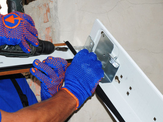
How to Replace the Main Gear at a Garage Door Opener
It is 6:00 AM and you are leaving for work. You press on the garage door opener wall button and listen to a subtle hum from your electric motor but the door failed to maneuver. In case your garage doors springs are intact chances are you garage door openers primary drive equipment has neglected. You can easily inspect your drive gears by simply clipping your garage door opener and taking away the metallic cover. The primary drive gear is made from a white plastic which normally will be your weak link in the opener. Several things can cause this equipment to fail. Some causes of wear are:
O Garage door out of equilibrium (Springs busted or in need of modification ) O Chain to tight a o Old age o Excessive use or higher cycle o Factory flaw or lack of grease at time of fabrication
Fixing the white gear is a very low cost, fast and simple do it yourself repair as long as you've got a few simple hand tools and then adhere to the safety measures. These gears are available online in various degrees of components.
Before you get started It's important for You to Have a record of the few Straightforward tools needed to accomplish this job: O Hammer o Half inch wrench or adjustable wrench or pliers o 3/8" Socket or Nut Driver o 1/4" Socket or Nut Driver o 5/16" Socket or Nut Driver o Flat Standard Screwdriver o 5/32" Punch or comparable
~WARNING ~ To prevent possible SERIOUS INJURY or perhaps DEATH out of electrocution, ALWAYS Disconnect the power cable out of your garage door from the outlet prior to proceeding with any repair or inspection.

Step #1 Ensure your garage door opener is currently unplugged. This step insures that nobody inadvertently tries to close or open the garage door when you are working in it or you don't inadvertently activate the door while servicing it.
Step #2 Disconnect the doorway from the outside trolley by dragging on the red disconnect rope and manually close the door.
CAUTION The Garage door MUST be in the completely closed position during all repairs and inspection.
Assuring that your garage door will be closed will guarantee that your door will not fall or make any movement that would lead to injury or direct you. We recommend that when the door is closed that you clamp the door down using a vise clamp or grip above one of these rollers to stop the door from being opened from the outside.
Step #3 Slacken the series or straps tension by losing the pressure nut on the garage door opener trolley. Typically that is nut and may be adjusted with a 1/2" wrench.
Step #4 Remove the sprocket or belt pulley retainer cap. Usually this has a clip on the back if you press in it will release.
Step #5 I always recommend marking the position of the chain or belt to the sprocket prior to removing. This can easily be done with white out, tape or any other means. This step helps assure that your chain or belt gets reinstalled in the correct position and makes for quick and easy reference if needed later. Remove the chain or belt from the sprocket and then slide the inner trolley to the closed position until it engages the outer trolley. Place loose chain/belt on the end of the rail closest to the sprocket. I typically duct tape the chain to prevent it from falling to the floor and getting all twisted and dirty.
Step #6 It is now time to remove both end covers and the main housing. The end cover are each attached by three or four 1/4" head screws that may be removed using a 1/4" nut driver or socket. Be sure to unplug the wire to the circuit board.
Step #7 Remove the retaining clip and the drive gear for the limits. Also at this time remove the limit switch assembly by squeezing the sides just below the bracket by the drive gears. There is no need to disconnect the wires as it is OK to leave this limit assembly hang by the wires. Do not make any adjustments to the limit assembly screws, this will insure that there is minimal adjustment needed to the limits after you complete your repair and run your garage door opener.
Step #8 Now its time to remove the RPM sensor this can be easily done by unplugging the wire harness and remove the RPM sensor from the securing tabs.
Step #9 Disconnect the red, blue and white wires from the motor. It is important that you note where these wires go. The same color wires go to the same terminals on the capacitor red/red and blue/blue.
Step #10 Remove the four 5/16" hex head screw that hold the motor into the frame of this garage door opener. Make sure you place your hand below the motor prior to removing the last screw to stop the motor from falling. Slide the motor rolling off the drive shaft and set in a secure place. (Not on top of the ladder for obvious reasons).
Step #11 Remove the three hex head screws holding the sprocket assembly to the major chassis employing a 5/16" nut driver or socket. Now it is time to decide if you want to replace the main gear only or the entire sprocket or all chain drive models 1984 to present.
Step #12 Skip this step if you are replacing the entire gear and sprocket or pulley assembly. If you are going to replace the drive gear support the driveshaft on a block of wood and drive the lower roll pin/Tension pin out with a 5/32" punch. See photo example below.
Step #13 Remove and replace the worm gear. Generally it is not necessary to substitute the worm gear unless it shows signs of wear. Should you would like to replace this equipment eliminate the rotating collar with a 1/8" hex wrench. Please be sure to note the location of each of these components as you disassemble so you can re-install in proper order. When you receive your gear kit, you will find there are parts not used in your model this is because these kits are universal and work with many models of Sears, Craftsman, Wayne Dalton, Master Mechanic, Liftmaster, True Value and other brands of garage doors openers. Only replace the parts that are used on your garage door opener. Remove the 3 nuts that hold the motor to the frame and then remove the worm gear. Install the new worm gear making sure the roll pin is properly seated in the new gear. Re-install other components in reverse order. After you complete this assembly I recommend you lube the worm gear so you do not forget.
Step #14 Begin reassembly in reverse order. Be sure to thoroughly lube the main drive gear and that grease is on each and every tooth. Attach the gear and sprocket or pulley assembly to the main chassis with the three 5/16" screws. Install the assembled motor framework to the chassis with the four 5/16" head screws and reattach the red, blue and white wires; now install the limit assembly and the limit drive gear making sure they mesh properly. You can now install the RPM sensor and reconnect wires. Install the metal cover and end panels, be sure to plug in the circuit board and reconnect photo eye and push button wires.
Step #15 Reconnect the power cord to the opener and cycle the opener until the sprocket completes a complete clockwise cycle. The trolley must be in the fully down position before installing the chain. Now you can remove the tape from the rail and reinstall the chain. The chain and sprocket reference mark should be close to lining up. Tighten the chain so that the chain is 1/2" over the bottom of the rail at midpoint for"T" style rails and 1/4" for square tube rails. Secure the chain tightening lock nut.
WARNING Note when adjusting and testing your garage door motor it is important to make sure no one is in the path of the moving door.
CAUTION It is important to know when testing your garage door opener it is possible to over cycle the motor and have the motor temporarily overheat and stop operating. To prevent this try and not operate the door opener more than 10 cycles without giving it 5-10 minutes to cool off
Step #16 Now run the opener and test to see if the door opens to the correct position and closes to the correct position. If you need to make adjustments use the travel adjustments screws to make fine adjustments. I recommend only making slight adjustments 1/4 turn or less at a time. For reference one full turn of the screw equals approx 2" of travel on 1/2 and 1/4 HP versions and 3" on 3/4 HP models.
Step #17 Once you have your doors travel adjustment correct it is time to adjust the force. This is the pressure that it takes to assure your door opener will operate safely. The first step in this process is to check the down force. With the door open simply activate the garage door opener and when the door reaches the half way point grasp the door from the bottom and try and stop it. If the door is hard to stop or does not stop decrease the down force adjustment in small increments until it reverse upon reasonable force. If the door does not close and the light begins to blink increase the down force adjustment in small increments until you can check the reversal at half way. Adjusting the force does not guarantee that your operator will reverse on 1-1/2" object at the floor. To learn more about adjusting the change at the floor find out the owner's manual or call the manufacturer.
1 note
·
View note
Text
How to Replace the Main Gear in a Garage Door Opener
It's 6:00 AM and you are leaving for work. You press the garage door opener wall button and hear a subtle hum from your electric motor but the door failed to move. If your garage doors springs are intact chances are you garage door openers main drive gear has failed. You can easily inspect your drive gears by unplugging your garage door opener and removing the metal cover. The main drive gear is made of a white plastic that typically is the weak link in the opener. Many things can cause this gear to fail. Some causes of wear are:
o Garage door out of balance (Springs broke or in need of adjustment)
o Chain to tight a
o Old age
o Excessive use or high cycle
o Factory defect or lack of grease at time of manufacture
Replacing the large white gear is a low cost, quick and easy do it yourself repair as long as you have a few simple hand tools and follow the safety precautions. These gears can be purchased online in a variety of levels of components.
Before you get started it is important for you to have a list of the few simple tools needed to accomplish this project:
o Hammer
o Half inch wrench or adjustable wrench or pliers
o 3/8" Socket or Nut Driver
o 1/4" Socket or Nut Driver
o 5/16" Socket or Nut Driver
o Flat Standard Screwdriver
o 5/32" Punch or similar
~WARNING ~
To prevent possible SERIOUS INJURY or even DEATH from electrocution, ALWAYS Disconnect the power cord from your garage door from the outlet before proceeding with any inspection or repair.
Step #1
Make sure your garage door opener is unplugged. This step insures that no one unintentionally attempts to open or close the garage door while you are working on it or you do not accidentally activate the door while servicing it.
Step #2
Disconnect the door from the outer trolley by manually pulling the red disconnect rope and manually close the garage door.
CAUTION
The Garage door MUST be in the fully closed position during all repairs and inspection.
Assuring that your garage door is closed will reassure that your door will not fall or make any movement that would cause injury or startle you. We recommend that once the door is closed that you clamp the door down using a vise grip or clamp above one of the rollers to prevent the door from being opened from the outside.
Step #3
Slacken the chain or belts tension by losing the tension nut on the garage door opener trolley. Typically this is nut and can be adjusted with a ½" wrench.
Step #4
Remove the sprocket or belt pulley retainer cap. Usually this has a clip on the back if you press in it will release.
Step #5
I always recommend marking the position of the chain or belt to the sprocket prior to removing. This can easily be done with white out, tape or any other means. This step helps assure that your chain or belt gets reinstalled in the correct position and makes for quick and easy reference if needed later. Remove the chain or belt from the sprocket and then slide the inner trolley to the closed position until it engages the outer trolley. Place loose chain/belt on the end of the rail closest to the sprocket. I typically duct tape the chain to prevent it from falling to the floor and getting all twisted and dirty.
Step #6
It is now time to remove both end covers and the main housing. The end cover are each attached by three or four ¼" head screws that can be removed with a ¼" nut driver or socket. Be sure to unplug the wire to the circuit board.
Step #7
Remove the retaining clip and the drive gear for the limits. Also at this time remove the limit switch assembly by squeezing the sides just below the bracket by the drive gears. There is no need to disconnect the wires as it is OK to leave this limit assembly hang by the wires. Do not make any adjustments to the limit assembly screws, this will insure that there is minimal adjustment needed to the limits after you complete your repair and run your garage door opener.
Step #8
Now its time to remove the RPM sensor this can be easily done by unplugging the wire harness and remove the RPM sensor from the securing tabs.
Step #9
Disconnect the red, blue and white wires from the motor. It is important that you note where these wires go. The same color wires go to the same terminals on the capacitor red/red and blue/blue.
Step #10
Remove the four 5/16" hex head screw's that hold the motor assembly to the frame of the garage door opener. Be sure to put your hand under the motor before removing the last screw to prevent the motor from falling. Slide the motor assembly off the drive shaft and place in a safe place. (Not on top of the ladder for obvious reasons).
Step #11
Remove the three hex head screws holding the sprocket assembly to the main chassis using a 5/16" nut driver or socket. Now it is time to decide if you want to replace the main gear only or the entire sprocket or all chain drive models 1984 to present.
Step #12
Skip this step if you are replacing the entire gear and sprocket or pulley assembly. If you are going to replace the drive gear support the driveshaft on a block of wood and drive the lower roll pin/Tension pin out with a 5/32" punch. See photo example below.
Step #13
Remove and replace the worm gear. In most cases it is not necessary to replace the worm gear unless it shows signs of wear. If you wish to replace this gear remove the shaft collar with a 1/8" hex wrench. Please be sure to note the location of each of these components as you disassemble so you can re-install in proper order. When you receive your gear kit, you will find there are parts not used in your model this is because these kits are universal and work with many models of Sears, Craftsman, Wayne Dalton, Master Mechanic, Liftmaster, True Value and other brands of garage doors openers. Only replace the parts that are used on your garage door opener. Remove the 3 nuts that hold the motor to the frame and then remove the worm gear. Install the new worm gear making sure the roll pin is properly seated in the new gear. Re-install other components in reverse order. After you complete this assembly I recommend you lube the worm gear so you do not forget.
Step #14
Begin reassembly in reverse order. Be sure to thoroughly lube the main drive gear and that grease is on each and every tooth. Attach the gear and sprocket or pulley assembly to the main chassis with the three 5/16" head screws. Install the assembled motor frame to the chassis with the four 5/16" head screws and reattach the red, blue and white wires; now install the limit assembly and the limit drive gear making sure they mesh properly. You can now install the RPM sensor and reconnect wires. Install the metal cover and end panels, be sure to plug in the circuit board and reconnect photo eye and push button wires.
Step #15
Reconnect the power cord to the opener and cycle the opener until the sprocket completes a complete clockwise cycle. The trolley must be in the fully down position before installing the chain. Now you can remove the tape from the rail and reinstall the chain. The chain and sprocket reference mark should be close to lining up. Tighten the chain so that the chain is ½" above the base of the rail at midpoint for "T" style rails and ¼" for square tube rails. Secure the chain tightening lock nut.
WARNING
Note when adjusting and testing your garage door motor it is important
to make sure no one is in the path of the moving door.
CAUTION
It is important to know when testing your garage door opener it is possible to over cycle the motor
and have the motor temporarily overheat and stop operating.
To prevent this try and not operate the door opener more than 10 cycles
without giving it 5-10 minutes to cool off
Step #16
Now run the opener and test to see if the door opens to the correct position and closes to the correct position. If you need to make adjustments use the travel adjustments screws to make fine adjustments. I recommend only making slight adjustments ¼ turn or less at a time. For reference one full turn of the screw equals approx 2" of travel on ½ and ¼ HP models and 3" on ¾ HP models.
Step #17
Once you have your doors travel adjustment correct it is time to adjust the force. This is the pressure that it takes to assure your door opener will operate safely. The first step in this process is to check the down force. With the door open simply activate the garage door opener and when the door reaches the half way point grasp the door from the bottom and try and stop it. If the door is hard to stop or does not stop decrease the down force adjustment in small increments until it reverse upon reasonable force. If the door does not close and the light begins to blink increase the down force adjustment in small increments until you can check the reversal at half way. Adjusting the force does not guarantee that your operator will reverse on 1-1/2" object at the floor. For more information on adjusting the reversal at the floor see your owner's manual or call the manufacturer.
Electric Gate repair Services Palm Beach County:
Electric gate repair
Electric gate repair atlantis
Electric gate repair belle glade
Electric gate repair boca raton
Electric gate repair boynton beach
Electric gate repair briny breezes
Electric gate repair cloud lake
Electric gate repair delray beach
Electric gate repair glen ridge
Electric gate repair golf
Electric gate repair greenacres
Electric gate repair gulf stream
Electric gate repair haverhill
Electric gate repair highland beach
Electric gate repair hypoluxo
Electric gate repair juno beach
Electric gate repair jupiter
Electric gate repair jupiter inlet colony
Electric gate repair lake clarke shores
Electric gate repair lake park
Electric gate repair lake worth beach
Electric gate repair lantana
Electric gate repair loxahatchee groves
Electric gate repair manalapan
Electric gate repair mangonia park
Electric gate repair north palm beach
Electric gate repair ocean ridge
Electric gate repair pahokee
Electric gate repair palm beach
Electric gate repair palm beach gardens
Electric gate repair palm beach shores
Electric gate repair palm springs
Electric gate repair riviera beach
Electric gate repair royal palm beach
Electric gate repair south bay
Electric gate repair south palm beach
Electric gate repair tequesta
Electric gate repair wellington
Electric gate repair westlake
Find Garage Door Services in Palm Beach County:
Garage Door repair atlantis
Garage Door repair belle glade
Garage Door repair boca raton
Garage Door repair boynton beach
Garage Door repair briny breezes
Garage Door repair cloud lake
Garage Door repair delray beach
Garage Door repair glen ridge
Garage Door repair golf
Garage Door repair greenacres
Garage Door repair gulf stream
Garage Door repair haverhill
Garage Door repair highland beach
Garage Door repair hypoluxo
Garage Door repair juno beach
Garage Door repair jupiter
Garage Door repair jupiter inlet colony
Garage Door repair lake clarke shores
Garage Door repair lake park
Garage Door repair lake worth beach
Garage Door repair lantana
Garage Door repair loxahatchee groves
Garage Door repair manalapan
Garage Door repair mangonia park
Garage Door repair north palm beach
Garage Door repair ocean ridge
Garage Door repair pahokee
Garage Door repair palm beach
Garage Door repair palm beach gardens
Garage Door repair palm beach shores
Garage Door repair palm springs
Garage Door repair riviera beach
Garage Door repair royal palm beach
Garage Door repair south bay
Garage Door repair south palm beach
Garage Door repair tequesta
Garage Door repair wellington
Garage Door repair westlake
0 notes
Text
How to Replace the Main Gear in a Garage Door Opener In San Lorenzo CA
It's 6:00 AM and you are leaving for work. You press the garage door opener wall button and hear a subtle hum from your electric motor but the door failed to move. If your garage doors springs are intact chances are you garage door openers main drive gear has failed. You can easily inspect your drive gears by unplugging your garage door opener and removing the metal cover. The main drive gear is made of a white plastic that typically is the weak link in the opener. Many things can cause this gear to fail. Some causes of wear are:
o Garage door out of balance (Springs broke or in need of adjustment) o Chain to tight a o Old age o Excessive use or high cycle o Factory defect or lack of grease at time of manufacture
Replacing the large white gear is a low cost, quick and easy do it yourself repair as long as you have a few simple hand tools and follow the safety precautions. These gears can be purchased online in a variety of levels of components.
Before you get started it is important for you to have a list of the few simple tools needed to accomplish this project: o Hammer o Half inch wrench or adjustable wrench or pliers o 3/8" Socket or Nut Driver o 1/4" Socket or Nut Driver o 5/16" Socket or Nut Driver o Flat Standard Screwdriver o 5/32" Punch or similar
~WARNING ~ To prevent possible SERIOUS INJURY or even DEATH from electrocution, ALWAYS Disconnect the power cord from your garage door from the outlet before proceeding with any inspection or garage door repair.
Step #1 Make sure your garage door opener is unplugged. This step insures that no one unintentionally attempts to open or close the garage door while you are working on it or you do not accidentally activate the door while servicing it.
Step #2 Disconnect the door from the outer trolley by manually pulling the red disconnect rope and manually close the garage door.
CAUTION The Garage door MUST be in the fully closed position during all repairs and inspection.
Assuring that your garage door is closed will reassure that your door will not fall or make any movement that would cause injury or startle you. We recommend that once the door is closed that you clamp the door down using a vise grip or clamp above one of the rollers to prevent the door from being opened from the outside.
Step #3 Slacken the chain or belts tension by losing the tension nut on the garage door opener trolley. Typically this is nut and can be adjusted with a ½" wrench.
Step #4 Remove the sprocket or belt pulley retainer cap. Usually this has a clip on the back if you press in it will release.
Step #5 I always recommend marking the position of the chain or belt to the sprocket prior to removing. This can easily be done with white out, tape or any other means. This step helps assure that your chain or belt gets reinstalled in the correct position and makes for quick and easy reference if needed later. Remove the chain or belt from the sprocket and then slide the inner trolley to the closed position until it engages the outer trolley. Place loose chain/belt on the end of the rail closest to the sprocket. I typically duct tape the chain to prevent it from falling to the floor and getting all twisted and dirty.
Step #6 It is now time to remove both end covers and the main housing. The end cover are each attached by three or four ¼" head screws that can be removed with a ¼" nut driver or socket. Be sure to unplug the wire to the circuit board.
Step #7 Remove the retaining clip and the drive gear for the limits. Also at this time remove the limit switch assembly by squeezing the sides just below the bracket by the drive gears. There is no need to disconnect the wires as it is OK to leave this limit assembly hang by the wires. Do not make any adjustments to the limit assembly screws, this will insure that there is minimal adjustment needed to the limits after you complete your repair and run your garage door opener.
Step #8 Now its time to remove the RPM sensor this can be easily done by unplugging the wire harness and remove the RPM sensor from the securing tabs.
Step #9 Disconnect the red, blue and white wires from the motor. It is important that you note where these wires go. The same color wires go to the same terminals on the capacitor red/red and blue/blue.

Step #10 Remove the four 5/16" hex head screw's that hold the motor assembly to the frame of the garage door opener. Be sure to put your hand under the motor before removing the last screw to prevent the motor from falling. Slide the motor assembly off the drive shaft and place in a safe place. (Not on top of the ladder for obvious reasons).
Step #11 Remove the three hex head screws holding the sprocket assembly to the main chassis using a 5/16" nut driver or socket. Now it is time to decide if you want to replace the main gear only or the entire sprocket or all chain drive models 1984 to present.
Step #12 Skip this step if you are replacing the entire gear and sprocket or pulley assembly. If you are going to replace the drive gear support the driveshaft on a block of wood and drive the lower roll pin/Tension pin out with a 5/32" punch. See photo example below.
Step #13 Remove and replace the worm gear. In most cases it is not necessary to replace the worm gear unless it shows signs of wear. If you wish to replace this gear remove the shaft collar with a 1/8" hex wrench. Please be sure to note the location of each of these components as you disassemble so you can re-install in proper order. When you receive your gear kit, you will find there are parts not used in your model this is because these kits are universal and work with many models of Sears, Craftsman, Wayne Dalton, Master Mechanic, Liftmaster, True Value and other brands of garage doors openers. Only replace the parts that are used on your garage door opener. Remove the 3 nuts that hold the motor to the frame and then remove the worm gear. Install the new worm gear making sure the roll pin is properly seated in the new gear. Re-install other components in reverse order. After you complete this assembly I recommend you lube the worm gear so you do not forget.
Step #14 Begin reassembly in reverse order. Be sure to thoroughly lube the main drive gear and that grease is on each and every tooth. Attach the gear and sprocket or pulley assembly to the main chassis with the three 5/16" head screws. Install the assembled motor frame to the chassis with the four 5/16" head screws and reattach the red, blue and white wires; now install the limit assembly and the limit drive gear making sure they mesh properly. You can now install the RPM sensor and reconnect wires. Install the metal cover and end panels, be sure to plug in the circuit board and reconnect photo eye and push button wires.
Step #15 Reconnect the power cord to the opener and cycle the opener until the sprocket completes a complete clockwise cycle. The trolley must be in the fully down position before installing the chain. Now you can remove the tape from the rail and reinstall the chain. The chain and sprocket reference mark should be close to lining up. Tighten the chain so that the chain is ½" above the base of the rail at midpoint for "T" style rails and ¼" for square tube rails. Secure the chain tightening lock nut.
WARNING Note when adjusting and testing your garage door motor it is important to make sure no one is in the path of the moving door.
CAUTION It is important to know when testing your garage door opener it is possible to over cycle the motor and have the motor temporarily overheat and stop operating. To prevent this try and not operate the door opener more than 10 cycles without giving it 5-10 minutes to cool off
Step #16 Now run the opener and test to see if the door opens to the correct position and closes to the correct position. If you need to make adjustments use the travel adjustments screws to make fine adjustments. I recommend only making slight adjustments ¼ turn or less at a time. For reference one full turn of the screw equals approx 2" of travel on ½ and ¼ HP models and 3" on ¾ HP models.
Step #17 Once you have your doors travel adjustment correct it is time to adjust the force. This is the pressure that it takes to assure your door opener will operate safely. The first step in this process is to check the down force. With the door open simply activate the garage door opener and when the door reaches the half way point grasp the door from the bottom and try and stop it. If the door is hard to stop or does not stop decrease the down force adjustment in small increments until it reverse upon reasonable force. If the door does not close and the light begins to blink increase the down force adjustment in small increments until you can check the reversal at half way. Adjusting the force does not guarantee that your operator will reverse on 1-1/2" object at the floor. For more information on adjusting the reversal at the floor see your owner's manual or call the manufacturer.
Article Source
0 notes
Text
Convertible Top Control Module: Diagram Information and Instructions H-M
2010 BMW 128i Convertible (E88) L6-3.0L (N51) BMW Repair Guide Page 1
Convertible Top Control Module: Diagram Information and Instructions
H-M
H1 Siren With Tilt Alarm Sensor
H2 Fanfare Horn, Low Range
H3 Fanfare Horn, High Range
H1a Horn, Anti-Theft Alarm System
H1b Siren and Tilt Alarm Sensor
H26 Rear Fog Light, Left (N14 Engine)
H29 Rear Fog Light, Right (N14 Engine)
H2a Left Horn
H2b Horn
H2c Horn
H3a Right Horn
H3b Horn 2
H3c Horn 2
H40 Park Distance Control Loudspeaker
H44 Right Front Speaker
H45 Parking Aid Speaker, Rear
H51 Woofer, Front Right
H52 Woofer, Rear Right
H53 Right Rear High Range Speaker
H54 Mid-Range Speaker, Front Right
H55 Mid-Range Speaker, Front Left
H56 Left Rear High Range Speaker
H58 Woofer, Front Left
H60 Woofer, Rear Left
H66 Subwoofer, Right
H75 Subwoofer, Front Left
H76 Subwoofer, Front Right
H77 Center Speaker
H82 Emergency Speaker
H83 Speaker, Left D-Pillar
H84 Speaker, Right D-Pillar
H8a Auxiliary Direction Indicator, Front Right
H8a Direction Indicator Light Repeater, Front Right
H9a Direction Indicator Light Repeater, Front Left
H34a Auxiliary Brake Light
H452 Flash Lamp
H50a Tweeter, Front Right
H53a Tweeter, Rear Right
H56a Tweeter, Rear Left
H59a Tweeter, Front Left
H66a Subwoofer, Left
H68a Mid-Range Speaker, Front Left
H68a Mid-Range Speaker, Front left
H69a Mid-Range Speaker, Front Right
H70a Mid-Range Speaker, Rear Left
H71a Mid-Range Speaker, Rear Right
H71a Mind-Range Speaker, Rear Right
H77a Speaker, Top Centre Instrument Panel
H78a Mid-Range Speaker, Rear Left Door
H79a Mid-Range Speaker, Rear Right Door
H472a Flashing Beacon 2
H472b Flashing Beacon 3
H9115 Mid-Range Speaker, Side Trim Panel Right
H9115 Mid-Range Speaker, Side Trim Panel, Right
H9117 Mid-Range Speaker, Side Trim Panel, Left
H16026 Rear Fog Light (Without N14 Engine)
I01003 Charging Socket, Rear
I01008 Circulation Pump, Independent Heater
I01009 Combustion Air Blower, Independent-Heater
I01010 Heater Plug, Independent Heater
I01012 Rear Window Aerial
I01032 Switch Block Multifunction Steering Wheel, Left
I01033 Switch Block Multifunction Steering Wheel, Right
I01046 Interference Suppression Capacitor For Ignition Coils
I01046 Suppression Capacitor For Ignition Coils
I01058 Ventilation Flap Motor, Left
I01059 Ventilation Flap Motor, Right
2010 BMW 128i Convertible (E88) L6-3.0L (N51) BMW Repair Guide Page 2
I01068 Relay, Terminal 30G
I01069 Relay, Terminal 15
I01086 Volute Spring
I01091 Rocker Switch, Left
I01092 Rocker Switch, Right
I01096 Steering Torque Sensor
I01103 TV Antenna, Rear Left Side Window
I01104 TV Antenna, Rear Right Side Window
I01110 Steering Wheel Heating Control Module
I01116 Hall Sensor, Cowl Panel Released
I01118 Steering Wheel Heating With Temperature Sensor
I01121 B+ Terminal Point, Luggage Well
I01134 Trunk Lid Resistor, Left
I01135 Trunk Lid Resistor, Right
I01139 BI-Stable Relay (Variant-Dependent)
I01139 Bi-Stable Relay (Variant-Dependent)
I01143 Antenna Amplifier, Left Side Window
I01144 Antenna Amplifier, Right Side Window
I01145 Antenna, Left Side Window
I01146 Antenna, Right Side Window
I01157 Seat Belt Positioner Controller, Driver
I01158 Seat Belt Positioner Controller, Front Passenger
I01159 Seat Position Sensor, Driver
I01160 Relay, Terminal 30G 2
I01162 Backpressure Flap Motor
I01163 Front Stratifying Air Flap Motor, Left
I01164 Front Stratifying Air Flap Motor, Right
I01165 Rear Stratifying Air Flap Motor, Left
I01166 Rear Stratifying Air Flap Motor, Right
I01167 Rear Footwell Flap Motor, Left
I01168 Rear Footwell Flap Motor, Right
I01170 Electric Auxiliary Heater, Rear
I01171 Inner Antenna, Luggage Compartment 2
I01172 Washer Pump Relay, Rear
I01173 Ground Distribution
I01174 Infrared Interface
I01179 Rear Spoiler Aerial
I01180 Microswitch, Air Distribution
I01181 Blower Motor, 3RD Row of Seats
I01182 Blower Button, 3RD Row of Seats
I01183 Auxiliary Heater Control Module, 3RD Row of Seats
I01184 Seat Position Sensor, Front Passenger
I01185 FM Antenna 1
I01185 FM Antenna 1 (Convertible)
I01186 FM Antenna 2
I01187 FM Antenna 3
I01187 FM Antenna 3 (Convertible)
I01188 FM Antenna 4
I01197 Microswitch, Coupling Fastener, Left
I01197 Microswitch, Coupling Fastener, Left, Closed
I01197 Microswitch, Coupling Fastener,Left, Closed
I01198 Hall Sensor 5.3
I01198 Hall Sensor, Rear Module Almost Closed
I01199 Hall Sensor 5.2
I01199 Hall Sensor, Rear Module Open
I01200 Microswitch 4.1
I01200 Microswitch, Cowl Panel Locked
I01201 Microswitch 4.2
I01201 Microswitch, Cowl Panel Unlocked
I01202 Microswitch 6.1
I01202 Microswitch, Coupling Fastener, Right
I01203 Hall Sensor 1.1
I01203 Hall Sensor, Roof Package Up
I01204 Hall Sensor 1.2
I01204 Hall Sensor, Roof Package Down
I01205 Hall Sensor 2.3
I01205 Hall Sensor, Roof Shells Partially Closed
I01206 Hall Sensor 2.4
I01206 Hall Sensor, Roof Shells Partially Open
I01207 Hall Sensor 5.1
2010 BMW 128i Convertible (E88) L6-3.0L (N51) BMW Repair Guide Page 3
I01207 Hall Sensor, Rear Module Closed
I01208 Hall Sensor 6.2
I01208 Hall Sensor, Coupling Fastener, Right
I01209 Drive Unit For Hardtop Lock
I01209 Engine Unlocking Convertible Top
I01209 Engine, Unlocking Convertible Top
I01211 Drive Unit For Boot Lid Lift, Left
I01212 Drive Unit For Boot Lid Lift, Right
I01213 Boot Lid Contact Switch, Bottom
I01217 Terminating Resistor D-CAN
I01220 RTTI Splitter
I01221 Split Door Lighting, Right
I01222 Split Door Lighting, Left
I01223 Rear Spoiler AM/FM Aerial
I01223 Rear Spoiler Am/FM Aerial
I01226 CAN Terminating Resistor (S65 Engine)
I01229 Hall Sensor, Main Pillar Erected
I01229 Hall Sensor, Main Pillar Erected
I01230 Hall Sensor, Main Pillar Taken Down
I01231 Hall Sensor, Tensioning Bar Extended
I01232 Hall Sensor, Clamping Bracket Erected
I01233 Hall Sensor, Clamping Bracket Taken Down
I01234 Hall Sensor, Cowl Panel Closed
I01234 Hall Sensor, Cowl Panel Locked
I01235 Incremental Encoder, Locking Motor
I01236 Hall Sensor, Convertible Top Compartment Lid Locked
I01237 Hall Sensor, Convertible-Top Compartment Lid Opened
I01238 TV Antenna, On Left In Bumper
I01239 TV Antenna, on Right In Bumper
I01241 Microswitch, Roof Shell 2 Closed, Right
I01242 Microswitch, Roof Shell 2 Closed, Left
I01243 Hall Sensor, Roof Panel 2 Packed
I01244 Microswitch, Rear-End Module, Closed, Right
I01244 Microswitch, Rear-End-Module, Closed, Right
I01245 Microswitch, Rear-End Module, Closed, Left
I01245 Microswitch, Rear-End-Module, Closed, Left
I01248 NOx Sensor Behind Catalytic Converter
I01249 Heating, SCR System
I01250 Heater, Active Tank
I01251 Temperature Sensor, Active Tank
I01252 Fuel Level Sensor, Active Tank
I01254 Valve 1 For Rectractable Hardtop
I01255 Valve 2 For Rectractable Hardtop
I01256 Valve 3 For Rectractable Hardtop
I01257 Hall Sensor, Stowage Lock, Left
I01258 Incremental Transducer, Direction
I01259 Incremental Transducer, Speed
I01260 Antenna, Digital Tuner
I01261 Antenna, Digital Tuner II
I01555 Component(S) According to Vehicle Equipment Level
I01555 Component(s) According to Vehicle Equipment Level
I13444 Heated Windscreen , Left
I13445 Heated Windscreen , Right
I14255 MOST-Bus Connector
I14255 Most-Bus Connector
I14286 Roof Operating Unit
I011032 Switch Block Malfunction Steering Wheel, Left
I011033 Switch Block Malfunction Steering Wheel, Right
I01111a Valve For Roof Segments
I01123a Valve 1 For Rear Module
I01123b Valve 1 For Convertible-Top Drive
I01124a Valve For Coupling Fastener
I01125a Hydraulic Oil Temperature Sensor
I01127a Valve 2 For Rear Module
I01127b Valve 2 For Convertible Top Drive
I01128a Valve 3 For Rear Module
I01128b Valve 3 For Convertible Top Drive
I011111a Valve For Roof Segments
K1 Compressor Relay
K2 Horn Relay
2010 BMW 128i Convertible (E88) L6-3.0L (N51) BMW Repair Guide Page 4
K4 Heater Blower Relay
K5 Cut-Out Relay, Electric Fan
K5 Washer Pump Relay, Front
K6 Relay, Headlight Washer
K9 Load-Shedding Relay, Terminal 15
K11 Windshield Wiper Relay
K13 Rear Window Defroster Relay
K19 Relay A/C Compressor
K21 Electric Fan Relay
K22 Electric Fan Relay 2
K2a Horn Relay
K36 Wiper Relay 1
K37 Wiper Relay 2
K91 Rear Wiper Relay
K96 Fuel Pump Relay
K126 Relay, Compressor, Air Suspension
K207 Relay, Automatic Soft-Close
K213 Relay, Electric Vacuum Pump
K411 Relay For Transceiver
K416 Windscreen Heater Relay
K424 Gun Mount Relay
K441 Relay, Direction Indicator Repeaters
K91a Relay 2 For Rear Window Wiper
K2068 Relay, Fuel Pump
K2085 Load Relay, SCR System
K2283 Preheater Relay
K2399 Relay, Additive Pump
K6300 DME Relay
K6301 Fuel Pump Relay
K6304 Secondary Air Pump Relay
K6317 Valvetronic Relay 2
K6319 VVT Relay
K6326 Power-Saving Relay, Terminal 15
K6327 Relay, Fuel Injector (N14 Engine)
K6327 Relay, Fuel Injectors
K6341 Relief Relay For Ignition Coils and Fuel Injectors
K6342 Relay, Volume Control Valves
K6539 Engine Breather Heating Relay
K9137 Cut-Out Relay, Electric Fan
K18363 Relay, Convertible Top 1
K18364 Relay, Convertible Top 2
K2003a DDE Main Relay
K6304A Secondary Air Pump Relay
K6304a Secondary Air Pump Relay
K6319a Valvetronic Relay (N12 Engine)
K18363a Relay 1 For Hardtop Drive Unit
K18364A Relay 2 For Hardtop Drive Unit
K18364a Relay 2 For Hardtop Drive Unit
M1 Drive, Longitudinal Seat Adjustment, Passenger's Side
M2 Drive, Seat-Angle Adjustment, Passenger
M2 Electric Fuel Pump
M3 Drive, Seat-Back Angle Adjustment, Passenger
M3 Wiper Module
M4 Lumbar Support Drive, Rear Passenger's Side
M4 Windshield Washer Pump
M7 Footwell Flap Motor, Front Right
M7 Headlight Washer Pump
M8 Rear Compartment Flap Motor
M9 Electric Fan
M9 Stratification Flap Motor, Front Left
M10 Drive For Passenger's Seat Lumbar Support
M11 Power Window Drive, Driver
M12 Wiper Module
M13 Power Window Drive, Passenger
M14 Electric Fuel Pump
M16 Central Locking Drive, Fuel Filler Flap
M17 Slide/Tilt Sunroof Drive Unit
2010 BMW 128i Convertible (E88) L6-3.0L (N51) BMW Repair Guide Page 5
M19 Steering Column Adjustment Motor
M20 Ventilation Flap Motor, Outer Left
M21 Driver'S Window Motor
M21 Driver's Window Motor
M21 Footwell Flap Motor, Front Left
M22 Ventilation Flap Motor, Centre Right
M23 Passenger'S Window Motor
M23 Passenger's Window Motor
M23 Ventilation Flap Motor, Centre Left
M24 Rear Stratifying Air Flap Motor, Right
M25 Fresh Air Flap Motor
M26 Blower Motor
M27 Sunroof Shade Drive
M28 Rear Compartment Footwell Flap Motor, Right
M29 Drive, Backrest-Head Adjustment, Passenger
M30 Blower Motor
M30 Blower Motor (IHKA Integrated Automatic Heating/Air Conditioning)
M30 Blower Motor (IHR Integrated Heater Control)
M30 Drive For Driver's Seat Lumbar Support
M31 Drive For Head-Restraint Height Adjustment, Driver
M31 Footwell Flap Motor
M31 Footwell Flap Motor (IHKA Integrated Automatic Heating/Air Conditioning)
M32 Drive, Seat-Back Angle Adjustment, Driver
M35 Auxiliary Water Pump
M36 Drive, Seat-Back Width Adjustment, Passenger
M37 Auxiliary Water Pump
M37 Drive, Seat-Depth Adjustment, Passenger
M38 Rear Compartment Blower Motor
M38 Ventilation Flap Motor
M39 Drive, Seat-Angle Adjustment, Driver's Seat
M3a Wiper Motor
M40 Drive Unit, Driver's Seat Forward/Backward Adjustment
M42 Lumbar Support-Active Seat Drive Unit, Front Passenger
M43 Rear Lid Lift Drive, Right
M44 Fuel Metering Pump, Independent Heating
M45 Drive For Head-Restraint Height Adjustment, Passenger
M46 Backrest Head Adjustment Drive, Driver's Seat
M48 Drive, Backrest-Head Adjustment, Passenger
M49 Seat Belt Positioner Motor, Left
M4a Lumbar Support Drive For the Driver's and/or Passenger's Side, Rear
M50 Drive, Longitudinal Seat Adjustment, Passenger's Side
M51 Drive, Seat-Angle Adjustment, Passenger
M52 Drive For Head-Restraint Height Adjustment, Passenger
M54 Seat Depth Adjustment Drive, Driver's Seat
M55 Circulation Pump, Independent Heater
M56 Drive For Head-Restraint Height Adjustment, Driver
M57 Drive For Rear Window Roller Sun Blind
M60 Drive Unit, Driver's Seat Height Adjustment
M61 Defroster Flap Motor
M62 Rear Stratifying Air Flap Motor, Left
M62 Seat Belt Positioner Motor, Right
M63 Secondary Air Injection Pump
M64 Drive, Seat-Height Adjustment, Passenger's Side
M65 Drive, Seat-Back Angle Adjustment, Passenger
M66 Power Window Drive, Driver's Side, Rear
M67 Power Window Drive, Passenger's Side, Rear
M68 Drive, Longitudinal Seat Adjustment, Driver's Side
M69 Rear Compartment Blower Motor
M69 Stratification Flap Motor, Front Right
M70 Drive, Seat-Angle Adjustment, Driver's Side
M71 Drive, Seat-Back Angle Adjustment, Driver
M72 Central Locking Drive, Fuel Filler Flap
M73 Drive, Backrest-Width Adjustment, Driver
M74 Lumbar Support-Active Seat Drive Unit, Driver
M74 Motor, Rear Window Roller Sun Blind
M77 Air-Distribution-Flap Motor, Rear Climate Control, L
M78 Air-Distribution-Flap Motor, Rear Climate Control, R
M79 Blower Motor, Rear Air Conditioning System
M80 Drive, Backrest-Head Adjustment, Driver's Side
M81 Radiator Shutter Drive Unit
2010 BMW 128i Convertible (E88) L6-3.0L (N51) BMW Repair Guide Page 6
M82 Lumbar Support Drive, Rear Driver's Side
M83 Ventilation Flap Motor, Outer Right
M84 Rear Compartment Footwell Flap Motor, Left
M85 Automatic Soft-Close Drive, Right
M85 Mixing Air Flap Motor, Rear Air-Conditioning System, Left
M85 Soft Close Automatic Drive, Right
M86 Mixing Air Flap Motor, Rear Air-Conditioning System, Right
M87 Electric Fan
M88 Rear Lid Lift Drive, Left
M89 Release Drive, Glovebox
M89 Roller Sun Blind Drive, Driver's Side, Rear
M90 Roller Sun Blind Drive, Passenger's Side, Rear
M91 Recirculated Air Flap Motor
M92 Central Locking Drive, Oddments Compartment
M93 Washer Pump For Headlight Washer System
M94 Windscreen Washer Pump
M94 Wiper Drive, Rear
M95 Rear Window Washer Pump
M98 Window Regulator Motor, Rear Left
M99 Fan 2, Infotainment
M99 Window Regulator Motor, Rear Right
M101 Convertible Top Drive
M106 Motor, Backrest Head Adjustment, Driver's Seat
M110 Motor, Backrest Head Adjustment, Passenger's Seat
M111 Fan 1, Driver's Seat Cushion
M111 Fresh Air/Recirculating Air Flap Motor
M111 Fresh Air/Recirculating Air Flap Motor (IHKA Integrated Automatic Heating/Air Conditioning)
M111 Fresh Air/Recirculating Air Flap Motor (IHR Integrated Heater Control)
M112 Fan 2, Driver's Seat Cushion
M113 Fan 3, Driver's Seat Cushion
M114 Fan 4, Driver's Seat Cushion
M115 Fan 5, Driver's Seat Cushion
M116 Fan 1, Driver's Seat Backrest
M117 Fan 2, Driver's Seat Backrest
M118 Fan 3, Driver's Seat Backrest
M119 Fan 4, Driver's Seat Backrest
M120 Fan 1, Passenger's Seat Cushion
M121 Fan 2, Passenger's Seat Cushion
M122 Fan 3, Passenger's Seat Cushion
M123 Fan 4, Passenger's Seat Cushion
M124 Fan 5, Passenger's Seat Cushion
M125 Fan 1, Passenger's Seat Backrest
M126 Fan 2, Passenger's Seat Backrest
M127 Fan 3, Passenger's Seat Backrest
M128 Fan 4, Passenger's Seat Backrest
M132 Drive For Locking Cowl Panel
M135 Electric Fan
M137 Seat Cushion Fan, Rear Driver's Side
M137 Steering Column Adjustment Motor
M142 Backrest Fan, Rear Driver's Side
M146 Seat Cushion Fan, Rear Passenger's Side
M148 Front Passenger's Active Seat
M149 Driver's Active Seat
M14a System Lock, Rear Passenger'S Side
M14a System Lock, Rear Passenger's Side
M150 Air Distribution Flap Motor
M150 Air Distribution Flap Motor (IHR Integrated Heater Control)
M151 Backrest Fan, Rear Passenger's Side
M152 Mixer Flap Motor
M152 Mixer Flap Motor (IHR Integrated Heater Control)
M153 Mixed Air Flap Motor, Left
M153 Mixed Air Flap Motor, Left (IHKA Integrated Automatic Heating/Air Conditioning)
M154 Mixed Air Flap Motor, Right
M154 Mixed Air Flap Motor, Right (IHKA Integrated Automatic Heating/Air Conditioning)
M156 Motor, Backrest Width Adjustment, Driver's Seat
M157 Motor, Backrest Width Adjustment, Passenger's Seat
M157 Steering Column Inclination Motor
M158 Blending Pump Unit
M159 E-Box Fan (7er-Reihe_F01/F02 Without N57 Engine)
M159 Fan 1, Driver's Seat Cushion
2010 BMW 128i Convertible (E88) L6-3.0L (N51) BMW Repair Guide Page 7
M15a System Lock, Rear Driver'S Side
M15a System Lock, Rear Driver's Side
M160 Fan 2, Driver's Seat Cushion
M161 Fan 3, Driver's Seat Cushion
M161 Vibration Motor
M162 Fan 4, Driver's Seat Cushion
M163 Fan 5, Driver's Seat Cushion
M164 Drive For Electric Motor-Driven Reel, Left
M165 Drive For Electric Motor-Driven Reel, Right
M179 Steering Gear
M17a Central Locking Drive, Trunk Lid
M17a Central Locking Drive, Trunk Lid (Without Convertible)
M17c Central Locking Drive Unit, Split Door, Right
M17d Central Locking Drive Unit, Split Door, Left
M180 Metering Pump
M184 Motor, Backrest Angle Adjustment, Driver's Side
M184 Motor, Backrest Angle Adjustment, FA Rear
M191 Motor, Driver's Seat Depth Adjustment
M192 Motor, Passenger's Seat Depth Adjustment
M20a Ventilation Flap Motor, Left
M20b Power Window Motor, Rear Driver'S Side
M20b Power Window Motor, Rear Driver's Side
M214 Drive Unit, Driver'S Seat Height Adjustment
M214 Drive Unit, Driver's Seat Height Adjustment
M216 Drive Unit, Driver'S Seat Forward/Backward Adjustment
M216 Drive Unit, Driver's Seat Forward/Backward Adjustment
M218 Drive Unit, Driver'S Seat Angle Adjustment
M218 Drive Unit, Driver's Seat Angle Adjustment
M218 Drive, Seat-Angle Adjustment, Driver's Seat
M220 Turbocharger Coolant Pump (N14 Engine)
M22a Ventilation Flap Motor, Right
M22b Power Window Motor, Rear Passenger'S Side
M22b Power Window Motor, Rear Passenger's Side
M300 Roller Cover Motor, Release, Left
M301 Roller Cover Motor, Release, Right
M35a Defroster Flap Motor
M35a Defroster Flap Motor (IHKA Integrated Automatic Heating/Air Conditioning)
M37a Circulating Pump, Auxiliary Heater
M407 Automatic Soft-Close Drive, Trunk Lid/Tailgate
M408 Automatic Soft-Close Drive, Driver's Door
M409 Automatic Soft-Close Drive, Passenger's Door
M410 Automatic Soft-Close Drive, Rear Left
M411 Automatic Soft-Close Drive, Rear Right
M455 Fan M-ASK/CCC
M50a Drive, Driver's Seat Angle Adjustment
M51a Drive, Driver's Seat Forward/Backward Adjustment
M52a Drive, Driver's Seat Height Adjustment
M53a Drive, Driver'S Seat Backrest Angle Adjustment
M53a Drive, Driver's Seat Backrest Angle Adjustment
M54a Drive, Driver's Seat Head Restraint Adjustment
M55a Drive For Driver's Seat Lumbar Support
M55b Vacuum Pump, Driver's Seat
M55b Vacuum Pump, Passenger's Seat
M55c Lumbar Support-Active Seat Drive Unit, Driver
M56a Drive For Passenger's Seat Lumbar Support
M56b Vacuum Pump, Passenger'S Seat
M56b Vacuum Pump, Passenger's Seat
M56c Lumbar Support-Active Seat Drive Unit, Front Passenger
M57a Drive, Passenger'S Head Restraint Adjustment
M57a Drive, Passenger's Head Restraint Adjustment
M58a Drive, Passenger'S Backrest Angle Adjustment
M58a Drive, Passenger's Backrest Angle Adjustment
M59a Drive, Passenger'S Seat Height Adjustment
M59a Drive, Passenger's Seat Height Adjustment
M60a Drive, Passenger'S Seat Forward/Backward Adjustment
M60a Drive, Passenger's Seat Forward/Backward Adjustment
M610 Parking Brake, Left
M615 Parking Brake, Right
M61a Drive, Passenger'S Seat Angle Adjustment
M61a Drive, Passenger's Seat Angle Adjustment
2010 BMW 128i Convertible (E88) L6-3.0L (N51) BMW Repair Guide Page 8
M79a Automatic Soft-Close Drive, Left
M79a Soft Close Automatic Drive, Left
M82a Lumbar Massage-Seat Drive, Driver's Side, Rear
M89a Unlock Drive Unit, Glove Compartment
M94a Wiper Drive, Rear Left
M94b Wiper Drive Unit, Rear Right
M96a Rear Window Lock
M0159 Fan 1, Passenger's Seat Cushion
M0160 Fan 2, Passenger's Seat Cushion
M0161 Fan 3, Passenger's Seat Cushion
M0162 Fan 4, Passenger's Seat Cushion
M0163 Fan 5, Passenger's Seat Cushion
M101a Hardtop Drive Unit
M107a Release Drive, Glovebox II
M119A Diagnostic Module For Fuel Tank Leakage
M119a Diagnostic Module For Fuel Tank Leakage
M132a Drive Unit, Lock and Sliding Canvas Sunroof
M137a Electric Steering Lock
M137a Electric Steering Lock
M137a Electric Steering Lock (As of 12/04)
M164a Fan 1, Driver's Seat Backrest
M164b Fan 1, Passenger's Seat Backrest
M165a Fan 2, Driver's Seat Backrest
M165b Fan 2, Passenger's Seat Backrest
M166a Fan 3, Driver's Seat Backrest
M166b Fan 3, Passenger's Seat Backrest
M167a Fan 4, Driver's Seat Backrest
M167b Fan 4, Passenger's Seat Backrest
M180a SCR Delivery Module
M1997 Radiator Shutter Drive Unit
M2327 Friction Wheel Drive
M2399 Additive Pump
M2458 SCR Metering Module
M4723 Rear Compartment Mixing Flap Motor
M4729 Front Mixing Flap Motor
M6035 Electric Coolant Pump
M6351 Valvetronic Actuator Motor
M6351 Valvetronic Actuator Motor (N12 Engine)
M6352 Valvetronic Actuator Motor 2
M6353 Actuator, Variable Valve Timing Gear
M6506 E-Box Fan
M6510 Starter
M8533 VTG Actuator
M8540 Drive Unit For Towing Hitch Release
M9149 Luggage-Compartment Fan 1
M9575 Throttle Valve
M14104 Visor Motor
M14105 Glass Roof Motor
M60353 Coolant Pump For Intercooler
M60354 Turbocharger Coolant Pump
M60811 Actuator Motor, Left
M60812 Actuator Motor, Right
M6510a Starter
M6510a Starter (S65 Engine)
M9910a Antenna Amplifier, Rear Window
M13734a Footwell Flap Motor, Left
M13735a Footwell Flap Motor, Right
(adsbygoogle = window.adsbygoogle || []).push({}); from Blogger https://ift.tt/3bVFo4T
0 notes
Text
Top-Quality Terminal Blocks & Spring Clamp Manufacturers – Elmex Electric Pvt. Ltd.
Elmex Electric Pvt. Ltd. in Vadodara specializes in high-quality terminal blocks, including Plug & Socket Terminal Block Spring Clamp solutions. As a leading clamp manufacturer in India, we deliver durable and efficient products designed to meet diverse industrial needs. Terminal blocks vadodara, Plug & Socket Terminal Block Spring Clamp, Clamp manufacturers in india.
Elmex Electric Pvt. Ltd. Add : 12, GIDC Estate, Makarpura, Vadodara -390010, Gujarat, India Ph : 02652642021 / 23 Mo : (+91)8905403005 Fax : 02652638646 mail : [email protected] Visit us at : https://elmex.net/ (+91)8905403006, (+91)8905902016
Facebook : https://www.facebook.com/ElmexControls/ Twitter : https://twitter.com/elmexcontrols LinkedIn : https://www.linkedin.com/company/elmex-controls-pvt.-ltd. Youtube : https://youtu.be/LOooD_SvEMo
0 notes
Text
High-Quality Terminal Blocks in India by Elmex Electric Pvt. Ltd.
Elmex Electric Pvt. Ltd. offers top-grade Terminal Blocks in India, ensuring reliable and efficient electrical connections. Located in Vadodara, our range includes the innovative Plug & Socket Terminal Block Spring Clamp, designed for secure and easy installations. Trust Elmex for superior performance in electrical systems. Terminal blocks in India, Terminal blocks vadodara, Plug & Socket Terminal Block Spring Clamp.
Elmex Electric Pvt. Ltd. Add : 12, GIDC Estate, Makarpura, Vadodara -390010, Gujarat, India Ph : 02652642021 / 23 Mo : (+91)8905403005 Fax : 02652638646 mail : [email protected] Visit us at : https://elmex.net/ (+91)8905403006, (+91)8905902016
Facebook : https://www.facebook.com/ElmexControls/ Twitter : https://twitter.com/elmexcontrols LinkedIn : https://www.linkedin.com/company/elmex-controls-pvt.-ltd. Youtube : https://youtu.be/LOooD_SvEMo
0 notes
Text
Quality Terminal Blocks and Spring Clamps in India - Elmex Controls Pvt Ltd.
Discover Elmex Controls Pvt Ltd.'s premium Plug & Socket Terminal Blocks with Spring Clamp technology, ideal for lighting pole connections and panel mounting in India. Ensure reliable electrical connections with Elmex.
Plug & Socket Terminal Block Spring Clamp, lighting pole terminal block, Panel Mounted Terminal Blocks Spring Clamp india
#Plug & Socket Terminal Block Spring Clamp#lighting pole terminal block#Panel Mounted Terminal Blocks Spring Clamp india
0 notes
Text
The Advantages of Panel-Mounted Terminal Blocks with Spring Clamps
Panel-mounted terminal blocks with spring clamps are an essential component in electrical and electronic systems, offering numerous advantages over traditional screw-type terminal blocks. Panel mounted terminal blocks spring clamps in India, manufactured and supplied by Elmex Controls Pvt. Ltd. are gaining popularity around the world due to their reliability, ease of use, and time-saving capabilities.
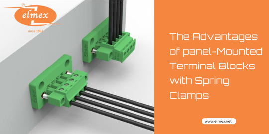
These clamps have become increasingly popular in India due to their numerous advantages over traditional wiring methods. In this article, let’s explore the importance of using panel-mounted terminal blocks with spring clamps, including enhanced reliability, improved safety, and superior performance.
Importance:
Firstly, their reliability is crucial for ensuring the smooth operation of electrical systems. Loose connections or faulty wiring can lead to interruptions in the power supply, equipment malfunction, or even safety hazards. Panel mounted terminal blocks spring clamps in India provide secure and stable connections, reducing the risk of such issues. This reliability is particularly vital in industries where downtime can result in substantial financial losses.
Secondly, the safety features offered by these terminal blocks play a significant role in protecting both equipment and personnel. Loose connections and short circuits can lead to electrical arcing, overheating, or electrical shocks. The spring clamps and clear separation between conductors in panel-mounted terminal blocks minimize these risks, making them a safer alternative to traditional wiring methods.
Moreover, the performance benefits of panel-mounted terminal blocks contribute to the overall efficiency and productivity of electrical systems. By maintaining optimal contact and reducing electrical resistance, these terminal blocks minimize power loss and voltage drops. This improves the performance of equipment, reduces energy consumption, and lowers operating costs.
Additionally, the ease of installation and maintenance provided by terminal blocks saves time and effort. Troubleshooting becomes simpler due to organized wiring and easy accessibility. Wiring errors are minimized, leading to quicker identification and resolution of issues. Furthermore, the flexibility and adaptability of terminal blocks allow for system modifications or expansions without the need for extensive rewiring, providing cost-effective solutions.
Reliability:
Reliability is a crucial aspect of any electrical system, and panel-mounted terminal blocks with spring clamps offer notable advantages in this regard. These terminal blocks provide secure and stable connections, ensuring consistent and uninterrupted electrical flow. The spring clamps exert constant pressure on the conductors, maintaining a reliable connection even in demanding environments with vibrations or temperature variations. This feature reduces the risk of loose connections, which can lead to electrical faults, downtime, and costly repairs.
Furthermore, panel-mounted terminal blocks simplify maintenance and troubleshooting processes. With traditional wiring methods, locating and fixing faulty connections can be time-consuming and challenging. However, with terminal blocks, the wiring is organized and easily accessible, allowing quick identification and resolution of issues. This enhances the overall reliability of the system, minimizing downtime and optimizing productivity.

Safety:
Safety is of utmost importance in electrical installations, and panel-mounted terminal blocks with spring clamps offer significant safety benefits. These terminal blocks have built-in features that help prevent electrical hazards. The spring clamps ensure a secure and vibration-resistant connection, reducing the risk of loose connections that can cause electrical arcing or overheating. Additionally, terminal blocks provide a clear separation between conductors, minimizing the chances of accidental contact and short circuits.
Panel-mounted terminal blocks also simplify installation and reduce the risk of wiring errors. The spring clamps allow for easy and tool-free wiring, eliminating the need for twisting and soldering wires. This reduces the chances of human error, such as loose connections or crossed wires, which can compromise safety. The clearly labelled and organized terminals make it easier to identify and verify correct wiring, ensuring proper circuit configurations.
Moreover, terminal blocks are designed to withstand high voltages and currents, offering excellent electrical insulation. They are manufactured using high-quality materials that provide resistance to heat, chemicals, and other environmental factors. These attributes enhance the overall safety and durability of the electrical system.
Performance:
Panel mounted terminal blocks spring clamps in India offered by Elmex Controls, deliver superior performance compared to traditional wiring methods offered by other companies. The spring clamps provide consistent pressure, maintaining optimal contact between the conductors. This ensures low electrical resistance, minimizing power loss and voltage drops. The reliable connection offered by terminal blocks improves the overall efficiency of the system, resulting in better performance and reduced energy consumption.
Additionally, panel-mounted terminal blocks facilitate easy customization and flexibility. They allow for quick and hassle-free reconfiguration or expansion of the electrical system, without the need for rewiring. This feature is particularly advantageous in industrial settings where frequent changes and upgrades are common.
Furthermore, terminal blocks offer compatibility with a wide range of wire sizes and types. They can accommodate various conductor materials, such as solid, stranded, or flexible wires. This versatility allows for greater flexibility in system design and installation.
Final Thoughts:
Panel mounted terminal blocks spring clamps in India have revolutionized electrical installations in India, offering reliability, safety, and superior performance. Their secure connections, simplified troubleshooting, enhanced safety features, and flexibility make them the preferred choice for a wide range of applications, from industrial automation to building installations. Embracing these terminal blocks supplied by Elmex Controls Pvt. Ltd. can significantly improve electrical systems in terms of efficiency, durability, and overall performance.
#Panel mounted terminal blocks spring clamp India#Component housing block spring clamp#Spring loaded terminal blocks#Plug & socket terminal block spring clamp#Micro terminal block spring clamp#spring loaded terminal connector#spring type terminal block#solar pv panel junction box India#solar pv branch connector India
2 notes
·
View notes
Text
Revolutionizing Connection Technology with Plug & Socket Terminal Block Spring Clamp
Elmex is a leading name in the field of electrical connection technology, and their plug and socket terminal block spring clamps are one of their most innovative offerings. These spring clamps have revolutionized the way electrical connections are made, providing a secure and reliable connection that is easy to install and maintain.

One of the key advantages of Elmex plug and socket terminal block spring clamps is their ease of use. Unlike traditional screw terminals, which require manual tightening and loosening, these clamps use a spring mechanism to create a tight, secure connection with minimal effort. This makes installation and maintenance much faster and more efficient, which is especially important in large-scale industrial applications.
Another advantage of Elmex plug and socket terminal block spring clamps is their reliability. The spring mechanism ensures a consistent level of contact pressure, which minimizes the risk of loose or intermittent connections. This is particularly important in applications where the connection must remain stable and secure over a long period of time, such as in power distribution systems.
Elmex plug and socket terminal block spring clamps are also highly versatile. They can be used with a wide range of wire sizes and types, making them suitable for a variety of applications. In addition, they can be easily mounted on a DIN rail or panel, providing flexibility in installation.

Elmex plug and socket terminal block spring clamps are also designed with safety in mind. They are made from high-quality, flame-retardant materials that meet industry safety standards. This ensures that they can be used in even the most demanding environments without compromising safety.
In conclusion, Elmex plug and socket terminal block spring clamps are a game-changer in the field of electrical connection technology. Their ease of use, reliability, versatility, and safety make them an ideal choice for a wide range of industrial and commercial applications. If you are looking for a secure and efficient way to make electrical connections, Elmex plug and socket terminal block spring clamps are the way to go.
#Plug & socket terminal block spring clamp#Micro terminal block spring clamp#Panel mounted terminal blocks spring clamp India#Component housing block spring clamp#Spring loaded terminal blocks#spring loaded terminal connector#spring type terminal block#solar pv panel junction box India#solar pv branch connector India#electrical wire termination technology#manufacturer#DIN Rail Mounted Connectors#switchgear industry#solar product#PCB connectors#digital voltmeter#digital ammeter#power and signal#current transformer#renewable energy#electrical company
4 notes
·
View notes