#Turbine Oil Cleaning and Flushing System
Explore tagged Tumblr posts
Visit Tumblr Blog
Explore Tumblr blogs with no restrictions, modern design and the best experience.
Last Seen Tumblr Blogs


Fun Fact
Tumblr has been providing a Korean-language service since 2013.
Text
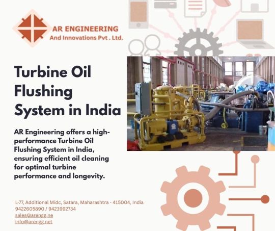
Turbine Oil Flushing System in India – Industrial Oil Cleaning & Purification Solutions
Looking for a high-performance Turbine Oil Flushing System in India? Welcome to OilFilterMachineIndia.com – India’s trusted name for industrial turbine oil flushing system solutions that ensure long-term turbine health, reduced wear, and zero contamination.
We design and supply Turbine Oil Cleaning and Flushing Systems tailored for power plants, refineries, and heavy industrial applications.
⚙️ Our Turbine Oil Flushing Systems Offer:
✅ Deep particulate removal and varnish cleaning
✅ Online and offline flushing options
✅ Ultra-fine filtration down to <1 micron
✅ Customized flow rate & pressure for each turbine type
✅ Portable turbine oil flushing units for on-site service
Whether you need an online turbine oil flushing service in India or a portable turbine oil flushing unit for emergency jobs, we’ve got you covered.
🛢️ We Specialize In:
Industrial turbine oil filtration and flushing system in India
Turnkey flushing solutions for gas & steam turbines
Reliable turbine oil cleaning systems for new and old turbines
Compact mobile units for remote field work
Continuous turbine oil purification in India using high-velocity flushing technology
Our systems are trusted by top power plants, OEMs, and EPC contractors nationwide.
✅ Why Choose Us?
Pan India supply & service support
ISO-certified design and quality
Proven performance with 100+ successful projects
Easy-to-use, low-maintenance machines
Custom design as per turbine specs
📍Get in Touch:
Looking for a Turbine Oil Flushing System that’s efficient, reliable, and built for Indian conditions?
🔗 https://oilfiltermachineindia.com/turbine-oil-flushing-system.html
#Turbine Oil Flushing System#Turbine Oil Flushing System in India#Industrial Turbine Oil Flushing System#Turbine Oil Cleaning and Flushing System#Turbine Oil Filtration and Flushing System in India#Online Turbine Oil Flushing Service in India#Turbine Oil Cleaning Systems#Portable Turbine Oil Flushing Unit#Turbine Oil Purification in India
0 notes
Text
Why Transformer Dry-Out Systems Are the Future of Power Maintenance
Introduction

The Challenges of Moisture in Transformers
Moisture is one of the most significant threats to transformer health. It degrades the insulating properties of transformer oil and solid insulation, leading to several issues, including:
Decreased Dielectric Strength: Excess moisture lowers the ability of the transformer oil and insulation to withstand electrical stress.
Accelerated Aging: Moisture accelerates cellulose degradation, shortening the lifespan of the transformer.
Increased Risk of Failures: Water content in insulation leads to overheating, arcing, and even catastrophic transformer failures.
Traditional moisture management practices often involve oil replacement or reactive maintenance, both of which are costly and time-consuming. This is where Transformer Dry-Out Systems step in as a game-changer.
What Are Transformer Dry-Out Systems?
Transformer Dry-Out Systems are advanced equipment designed to remove moisture from transformer oil and solid insulation without requiring a shutdown. These systems use innovative technologies such as vacuum dehydration, molecular sieve filtration, or thermodynamic processes to extract water from the system efficiently. Unlike traditional methods, dry-out systems provide a continuous, in-service solution, enabling real-time moisture control.
Benefits of Transformer Dry-Out Systems
Oil testing includes a variety of analytical procedures designed to evaluate the condition and properties of insulating oil in transformers. These tests can be categorized into the following key areas:
Enhanced Transformer Reliability Moisture reduction improves the dielectric strength of transformer oil, ensuring stable performance under varying load conditions. With dry-out systems, the risk of dielectric breakdown is significantly reduced, enhancing overall system reliability.
Extended Transformer Lifespan By removing moisture from solid insulation, transformer dry-out systems slow down the aging process of cellulose insulation. This extends the operational life of transformers, maximizing return on investment.
Cost Savings on Maintenance Transformer failures are costly, often requiring significant repairs or complete replacements. Dry-out systems prevent such failures by maintaining optimal moisture levels, reducing the need for reactive maintenance and costly downtime.
Real-Time Monitoring and Control Many modern dry-out systems are equipped with sensors and IoT-enabled technologies that provide real-time data on moisture levels, temperature, and oil quality. This allows for predictive maintenance strategies and improved decision-making.
Environmental Sustainability Replacing transformer oil generates waste and requires additional resources. Dry-out systems reduce the frequency of oil replacements, contributing to a more sustainable maintenance approach.
Key Technologies in Transformer Dry-Out Systems
1.Vacuum Dehydration
Vacuum dehydration is a proven method for removing dissolved and free water from transformer oil. By subjecting the oil to a high vacuum, water is evaporated at low temperatures, ensuring the preservation of the oil's chemical properties.
2.Molecular Sieve Filtration
Molecular sieves are specialized materials with microporous structures that adsorb moisture from transformer oil. This method is highly effective in maintaining oil purity and preventing re-contamination.
3.Thermodynamic Separation
This advanced technique leverages temperature and pressure differentials to separate water molecules from oil. Thermodynamic separation is particularly effective in high-capacity transformers.
Applications of Transformer Dry-Out Systems
1. Power Generation Plants
In power generation facilities, transformers operate under high loads and are critical for uninterrupted power supply. Dry-out systems ensure these transformers remain moisture-free, reducing the likelihood of outages.
2. Industrial Power Distribution
Industries rely heavily on transformers to power operations. Dry-out systems enable industries to maintain uninterrupted production schedules by preventing transformer failures.
3. Renewable Energy Systems
Renewable energy projects, such as wind and solar farms, depend on transformers for efficient power distribution. Transformer dry-out systems enhance the reliability and efficiency of these setups.
4. Utility Networks
In utility networks, where transformers are spread across vast geographical areas, dry-out systems provide an efficient and scalable solution for moisture management.
Minimac Systems’ Transformer Dry-Out Solutions
At Minimac Systems, we specialize in providing state-of-the-art solutions that redefine transformer maintenance. Our Transformer Dry-Out Systems are designed with cutting-edge technology to ensure effective and efficient moisture removal without the need for downtime.
Key Features of Minimac Transformer Dry-Out Systems
High-Efficiency Moisture Removal:Our systems are equipped with advanced vacuum dehydration and thermodynamic separation technologies for unparalleled moisture extraction.
Compact Design:Minimac dry-out systems are portable, allowing easy deployment across sites, even in remote areas.
Real-Time Monitoring:Integrated sensors and IoT compatibility provide actionable data for predictive maintenance strategies.
User-Friendly Interface:Our systems are designed for intuitive operation, requiring minimal training for on-site staff.
Environmentally Conscious:With minimal oil wastage, our systems align with global sustainability goals.
Why Choose Minimac Systems?
Proven Expertise:With years of experience in transformer maintenance solutions, Minimac Systems is a trusted name in the industry.
Custom Solutions:We tailor our systems to meet the unique requirements of every client, ensuring maximum effectiveness.
Reliable Support: From installation to routine maintenance, our team offers comprehensive support services to ensure uninterrupted operations.
Comprehensive Maintenance and Support Services
Implementing Transformer Dry-Out Systems is only the beginning of effective transformer maintenance. To maximize the performance and lifespan of these systems, dedicated maintenance and support services play a critical role.
1. Regular Performance Assessments
Scheduled inspections ensure that the dry-out system continues to operate at peak efficiency. These checks identify any wear, blockages, or system inefficiencies before they escalate into significant issues.
2. System Calibration and Upgrades
Advanced systems may require periodic calibration to ensure accurate moisture detection and removal. Upgrades to software and hardware ensure the system remains compatible with modern operational demands.
3. Emergency Troubleshooting and Repairs
Expert service teams provide immediate assistance during unexpected malfunctions. This minimizes downtime and prevents prolonged exposure to moisture that could damage the transformer.
4. Comprehensive Training Programs
Operators and maintenance teams benefit from hands-on training programs, enabling them to effectively manage the dry-out system and respond to anomalies promptly.
5. Customized Maintenance Plans
Tailored service plans take into account the specific operational environment and transformer requirements, ensuring optimized performance and prolonged equipment life. By integrating routine maintenance with reliable support services, transformer dry-out systems deliver unmatched value and dependability for the power sector.
Why Transformer Dry-Out Systems Are the Future
As the power industry evolves to meet growing demands, reliability and efficiency have become non-negotiable. Transformer dry-out systems align perfectly with these requirements. Here's why they represent the future of power maintenance: 1. Proactive Maintenance
The shift from reactive to proactive maintenance is a significant trend in the power sector. Dry-out systems enable utilities to address moisture issues before they escalate into costly failures.
2. Digital Integration
Modern dry-out systems are compatible with digital monitoring tools and SCADA (Supervisory Control and Data Acquisition) systems. This integration supports data-driven maintenance and enhances operational efficiency.
3. Regulatory Compliance
Governments and regulatory bodies are emphasizing sustainability and operational efficiency in power systems. By minimizing waste and improving transformer performance, dry-out systems help organizations comply with these standards.
4. Cost-Effectiveness
With increasing pressure to reduce operational costs, utilities and industries are adopting solutions that offer long-term savings. Dry-out systems fit this need by reducing maintenance costs and extending equipment life.
Conclusion
Transformer Dry-Out Systems are transforming the landscape of power maintenance by offering a reliable, efficient, and sustainable solution to moisture management. As the industry moves toward more proactive and data-driven maintenance strategies, these systems will play a pivotal role in ensuring the longevity and reliability of transformers. Incorporating comprehensive maintenance and support services further enhances the value of these systems, ensuring they deliver optimal performance throughout their lifecycle. Adopting a transformer dry-out system is not just an investment in equipment—it's an investment in the future of power infrastructure.
Are you ready to future-proof your transformer maintenance strategy?
Choose Minimac Systems’ Transformer Dry-Out Solutions for superior reliability, cost savings, and operational efficiency.
Click here to learn more about Minimac Systems Transformer Dry-Out System: https://www.minimacsystems.com/transformer-dryout-system
Contact us today to learn how the Minimac Transformer Dry-Out System can transform your lubrication practices and ensure the success of your operations!
#frf#oil flushing#minimac systems#power#minimac#oil & gas#hydraulic oil#lube oil filter#contamination#hydraulic oil filter#chemical cleaning flushing#chemical flushing#tofs#elc#bdv#testing kit#oil#oil analysis#oil and gas#turbine oilanalysis maintenance lubrication reliability contaminationcontrol oil powerplants oilfiltration rotatingequipment mechanical bre#power industry#metal#mining
0 notes
Text
Upgrade Your Industrial Cleaning Process with a Multi Stage Washer from Leela Electronics
Introduction: Industrial Cleaning Beyond the Basics
In today's competitive industrial landscape, maintaining cleanliness and operational hygiene is more important than ever. Whether in automotive, aerospace, manufacturing, or healthcare sectors, proper component cleaning can directly influence performance, product quality, and safety compliance. One of the most advanced tools available today is the Multi Stage Washer—a system that offers efficient, repeatable, and deep-cleaning performance.
At Leela Electronics, we specialize in manufacturing high-performance Multi Stage Washer systems tailored for demanding applications. Our washers are built to deliver consistent cleaning results across multiple industries while ensuring sustainability, reliability, and efficiency.

What Is a Multi Stage Washer?
A Multi Stage Washer is a comprehensive cleaning system that integrates several stages—such as washing, rinsing, ultrasonic cleaning, drying, and more—into a single unit. Each stage serves a specific purpose, allowing for complete and consistent cleaning of parts or components.
Unlike traditional single-tank machines, a Multi Stage Washer is engineered to handle high-throughput operations, clean complex parts, and reduce manual intervention. At Leela Electronics, our washers are customizable based on the industry, material, and level of contamination.
Why Choose a Multi Stage Washer from Leela Electronics?
1. Custom-Built Systems for Your Industry
Our Multi Stage Washer machines are not off-the-shelf solutions. We design them specifically for the unique requirements of each industry—be it heavy grease removal for automotive parts or precision cleaning for surgical tools. You choose the number of stages, type of cleaning, and automation level. We handle the engineering.
2. Advanced Ultrasonic Cleaning Integration
Many of our systems include ultrasonic cleaning stages that use cavitation to reach microscopic crevices. This non-invasive technology allows for the effective removal of stubborn contaminants without damaging the surface.
3. Eco-Friendly and Cost-Efficient
At Leela Electronics, sustainability is a priority. Our Multi Stage Washer systems use water and chemical solutions efficiently, often recycling them to reduce waste. This minimizes both your environmental footprint and operational costs.
4. High-Grade Construction and Durability
All our Multi Stage Washers are constructed with industrial-grade stainless steel, designed to endure 24/7 operations in demanding environments. Our machines are robust, corrosion-resistant, and built to last.
5. Automation and Safety
Equipped with digital PLC controls, programmable cleaning cycles, and safety interlocks, our Multi Stage Washer systems are easy to operate and monitor. They reduce human error, improve efficiency, and ensure operator safety.
Core Stages in a Multi Stage Washer
While configurations can vary, a typical Multi Stage Washer may include:
Stage 1: Pre-Wash or Degreasing Removes heavy oils, dirt, and particulates from surfaces.
Stage 2: Ultrasonic Cleaning Cavitation bubbles reach into fine grooves and complex geometries.
Stage 3: Rinsing Flushes away loosened contaminants and detergent residues.
Stage 4: Final Rinse (Optional with DI Water) Ideal for precision applications where purity matters.
Stage 5: Drying Hot air or vacuum drying ensures parts are moisture-free and ready for use or assembly.
Each Multi Stage Washer can be configured with more or fewer stages based on cleaning requirements.
Industries That Benefit from a Multi Stage Washer
Leela Electronics serves a wide range of industries with our advanced Multi Stage Washer solutions:
Automotive – Cleaning engine blocks, gear parts, and transmission components
Aerospace – Precision cleaning of avionics and turbine parts
Electronics – Removing flux, oils, and particulates from PCBs
Medical & Pharmaceutical – Cleaning surgical tools and lab equipment
Metalworking & Fabrication – Preparing parts for coating or welding
No matter your industry, a Multi Stage Washer improves efficiency, reduces rework, and supports better end-product quality.
Key Features of Leela Electronics’ Multi Stage Washer
Our Multi Stage Washer units are designed for performance and flexibility:
Modular design for easy scalability
Custom tank sizes and layouts
Digital temperature and timer control
Oil skimmers and filtration systems
Stainless steel baskets and lifts
Optional conveyor-based or robotic handling
This attention to engineering detail ensures that every Multi Stage Washer we build provides unmatched performance and value.
Why Leela Electronics?
Founded in 2007, Leela Electronics has grown into a leading manufacturer of ultrasonic and industrial cleaning systems. We combine technical expertise with a customer-first approach, ensuring that each Multi Stage Washer meets your exact specifications.
We don’t just sell machines—we deliver complete cleaning solutions backed by:
Consultation and design services
On-site installation and training
Preventive maintenance support
Spare parts availability and upgrades
Client Testimonials
"Our production line experienced a major quality boost after installing Leela Electronics' Multi Stage Washer. The cleaning process is now faster, more consistent, and eco-friendly." — Operations Manager, Automotive OEM
Conclusion: A Smarter Way to Clean
Industrial cleaning has evolved—and so should your equipment. With a Multi Stage Washer from Leela Electronics, you get more than just clean parts. You get improved efficiency, consistent quality, reduced downtime, and long-term savings.
Whether you're looking to improve an existing process or build a new cleaning line from scratch, our expert team is here to guide you every step of the way.
Contact Us
Looking to invest in a powerful, reliable Multi Stage Washer? Reach out to Leela Electronics today and let us design a customized cleaning solution for your facility.
1 note
·
View note
Text
Understanding Steam Blow Service and Procedure in Texas
In industrial processes, steam blowing is an essential maintenance procedure used to clean piping systems, ensuring the efficient operation of steam turbines, boilers, and other critical equipment. A steam blow service involves the use of high-pressure steam to remove any debris, dirt, and impurities that may accumulate in the system during installation or routine operations. In Texas, where industries rely on robust and reliable steam systems, understanding the steam blowing procedure is crucial for maintaining the integrity and longevity of equipment.
What is Steam Blowing?
Steam blowing is the process of using high-pressure steam to clear piping systems, typically in newly installed or repaired steam systems. The steam, generated at high pressures, is blown through the pipes at high velocity to remove any construction debris, oil, dirt, or other contaminants that may have been left behind after installation or maintenance. It is a necessary step before a system can be safely and efficiently put into operation.
The procedure ensures that the system is clean, free of any impurities, and capable of performing at its optimal capacity. It also reduces the risk of potential damage to sensitive components like turbine blades and valves, which could be impacted by foreign particles.
Why is Steam Blowing Important in Texas?
In Texas, the industrial sector relies heavily on steam systems, especially in power generation, petrochemical, and manufacturing industries. The need for a reliable steam system is paramount as even a small blockage or buildup of impurities can lead to costly downtime and reduced efficiency. Steam blowing helps mitigate these risks by ensuring that the system is free of contaminants.
Texas’s industrial plants operate in high-demand environments, often requiring large amounts of steam. This makes it even more critical to ensure that all components are thoroughly cleaned before the system is fully engaged. Additionally, the harsh Texas weather conditions can cause environmental factors like dust and debris to accumulate in equipment. As a result, steam blow service in Texas plays a crucial role in preserving the life of expensive machinery.
The Steam Blowing Procedure in Texas
The steam blowing procedure in texas typically follows a series of well-defined steps, designed to ensure that the piping system is properly cleaned and prepared for use. Here is an overview of the procedure:
Preparation and Inspection Before starting the steam blowing process, it’s essential to prepare the system. Technicians inspect the piping network, ensuring there are no leaks or weaknesses. All valves, flanges, and connections are checked for proper sealing. The entire system is set up to withstand the high-pressure steam that will flow through it.
System Flushing In some cases, a flushing procedure may be carried out before steam is introduced. This step is particularly important if the piping system is new and may contain installation debris or if the pipes have not been cleaned in a while. Flushing is done with water to remove large particles and dirt.
Steam Injection High-pressure steam is then injected into the piping system. The steam is blown at a velocity that is capable of dislodging any remaining particles inside the pipes. This is the most critical step in the steam blowing procedure, as the high-pressure steam ensures the system is completely cleaned.
Monitoring and Observing During the steam blowing process, technicians monitor the system closely. They track the steam flow, pressure, and any debris being ejected from the pipes. The goal is to ensure that all contaminants have been effectively removed.
Post-Blowing Inspection After the steam blowing process is complete, a final inspection is conducted to verify that the system is free of contaminants and fully operational. The pipes are checked for leaks, and the equipment is tested to ensure it is functioning correctly.
System Shutdown and Cleaning Once the steam blowing procedure is completed, the system is allowed to cool down, and any remaining water is removed. The pipes are thoroughly cleaned and dried, making sure they are ready for normal operation.
Conclusion
Steam blow services are a crucial part of maintaining the efficiency and longevity of steam systems in Texas. By following a meticulous procedure, industrial plants can ensure that their equipment runs smoothly, avoiding downtime and costly repairs. Whether it’s a newly installed system or one that’s been in service for years, a proper steam blow procedure is vital to ensure the highest performance standards are met. For industries in Texas, investing in a reliable steam blow service is a step toward ensuring optimal operational efficiency and protecting valuable equipment.
0 notes
Text
Identifying the Most Common Audi Engine Problems: Causes and Solutions

Audi vehicles are renowned for their performance, luxury, and advanced engineering. However, like any car, they are not immune to engine problems. Understanding the common issues, their causes, and potential solutions can help you maintain your Audi’s reliability and performance.
1. Oil Leaks
Causes:
Worn gaskets or seals, such as valve cover gaskets.
A damaged oil pan or loose drain plug.
A malfunctioning oil filter.
Solutions:
Regularly inspect gaskets and seals for wear and replace them when necessary.
Check for visible oil leaks and address them promptly to prevent engine damage.
2. Excessive Oil Consumption
Causes:
Piston ring wear, leading to oil leakage into the combustion chamber.
Valve seal deterioration.
Use of incorrect oil viscosity.
Solutions:
Use manufacturer-recommended oil grades.
Regularly monitor oil levels and refill as needed.
Consult a mechanic to assess internal engine wear and perform repairs.
3. Timing Chain Tensioner Failure
Causes:
Wear and tear over time.
Infrequent oil changes causing poor lubrication.
Solutions:
Replace the timing chain tensioner as part of preventive maintenance.
Stick to Audi's recommended oil change intervals to ensure proper lubrication.
4. Engine Misfires
Causes:
Faulty ignition coils or spark plugs.
A clogged fuel injector.
Carbon buildup in the intake valves, especially in direct-injection engines.
Solutions:
Replace ignition components as recommended in the maintenance schedule.
Use quality fuel and consider periodic fuel injector cleaning.
For carbon buildup, opt for walnut blasting or similar cleaning methods.
5. Cooling System Failures
Causes:
Leaks in the radiator, hoses, or water pump.
Thermostat or coolant temperature sensor malfunctions.
Old or incorrect coolant.
Solutions:
Regularly inspect the cooling system for leaks and replace faulty components.
Flush and replace coolant every 2-3 years using Audi-approved products.
6. Turbocharger Problems (in Turbocharged Engines)
Causes:
Lack of oil lubrication.
Carbon buildup on the turbine.
Worn or damaged bearings.
Solutions:
Ensure timely oil changes to prevent oil starvation.
Use high-quality fuel to reduce carbon deposits.
Address unusual noises or loss of power immediately with professional diagnostics.
7. PCV Valve Issues
Causes:
Blockage or malfunction of the Positive Crankcase Ventilation (PCV) valve.
Oil contamination in the valve.
Solutions:
Replace the PCV valve as part of regular maintenance.
Inspect the valve during oil changes for signs of failure.
Preventive Maintenance Tips for Audi Engines
Follow Audi’s recommended maintenance schedule.
Use OEM (Original Equipment Manufacturer) parts for replacements.
Monitor the engine for unusual sounds, smells, or warning lights.
Invest in professional diagnostic services if you notice performance issues.
By addressing these common engine problems proactively, you can maintain the performance and longevity of your Audi. Regular inspections and timely repairs by Audi-certified technicians will ensure a smooth driving experience and help avoid costly breakdowns.
#audi car#audi engine problem#audi engine service#audi service center#audi car maintenance#audi car mechanic
0 notes
Text
High pressure filter element YD0110D10BN/HC for GMR Turbine generator parts
"High pressure filter element YD0110D10BN/HC for GMR Turbine generator parts YOYIK produced by the development of agents. I plant production of various types of accessories up to tens of thousands of varieties, commodity varieties have been widely covered in the power plant hydrogen oil and water systems, roof pump system, regeneration system equipment, anti-fuel system, recycling system, sealed oil system, stator cooling water system, Purification equipment and other important system. Mainly used in power plants, steel mills, cement plants, chemical plants, shipyards and many other areas of industrial areas, but also to promote high-quality products, establish a brand image to lay a good foundation.
Yoyik can offer many spare parts for power plants as below:
DF-High pressure filter element YD0110D10BN/HC-DF
EH oil main pump discharge filter HQ25.600.14Z filter TZX-E16010 inline water filter SWF5 line filter element SDGLQ-50T-30 filter HX.BH-16010W Wind power filter PA25/H80V-10 actuator inlet filter (flushing) DP6SH201EA01V/F oil filter wrench SWUX-63×30 filter TFX-1000180 replacement filter SC0801-11 pp water filter SGLQB-1000A oil filter housing PQX-50×5Q3 water cleaning filter DLS-800 filter pressure hydraulic housing HQ25.300.15Z filter HX-63020 water filter machine purification system MSL-125 bulk oil filters PI 1710/6 oil filter tool HFX-250×20Q pp water filter SG125/0.8 filter SWCQX-70050 bulk oil filters ZU-H400×10 filter CFF2X-51080 filter 0950R010BN3HC/-V machine oil filter ZX-40×80 Main Pump Inlet Filter Element A100E-589000A-33 pp cartridge filter DLS-150 oil-return filter (working) DR405EA03V/-W hydraulic oil filter element HC4244-20H water machine filter KLS-100I industrial water filters WFF-150-1 hydraulic oil filters EH30-00-00 pp filter cartridge making machine SWF1 pp melt blown filter machine DLS-800 pp spun filter cartridge making machine DLS-600 hydraulic duplex oil filter F600-12Z filter FBX-400*30 High pressure filter element YD0110D10BN/HC
line filter element FX-160×3H water filter purifier SG-65/0.7 filter hydraulic oil TZX2-40×20Q2 melt blown filter cartridge DLS-500 cross reference oil filter LH0160D80BN3HC filter ZL366-2530 melt blown filter SG-65/0.7 filter V6021V4C03 high pressure hydraulic filter HFX-630×20Q hydraulic oil filter housing FAX(NX)-1000×10 best oil filter TFX-63×100 Water filter element DSG-65/08 filter EH50A-02-03 filter replacements HCY0212FK39H hydraulic duplex oil filter SFAX-800×5 water filter cartridge quick SL-31/45 stainless steel filter cartridge YSF-10-60 pp spun cartridge filter machine SL-9/50.03 activated carbon filter cartridge honeycomb 21FX5121-110×250/20 high pressure hydraulic filter XUI-A160×50S filter HC9600FKT8H filter NX-1603 cross reference oil filter TZX-E100×20Q2 automobile filter element ZL12BX-122/180 lube oil filters PI4130Smx25 automobile filter element ZU-H100×30S string wound filter DLS-600 automobile filter element YSF13-4.2J filter QYLX-40030Q2 water filter cartridge DLS-200 filter HCY-45108EOJ4H pp filter element KLS-100I oil press with oil filter WU-800×100-J hydraulic line filter element HQ25.600.11Z filter TZX2W-10180 filter ZX-250*180 High pressure filter element YD0110D10BN/HC
DFYLSYC-2024-7-1-A
0 notes
Text
VARTECH TECHNOLOGY: AN UNBELIEVABLY EASY METHOD THAT WORKS FOR YOUR GAS TURBINE
To understand how VARTECH Technology can work incredibly well for your Gas Turbine, it is important to understand varnish and the problem it creates.
Varnish is a broad term covering various kinds of deposits in oil systems. Some types are rigid and firm, others sticky, and others are commonly referred to as sludge. However, the common factor is that they typically begin from the degradation of the oil in the system.
Varnish usually forms and sticks in areas that are extremely hot or very cool and sluggish.
Now, measuring or finding varnish is an enormous challenge since varnish does not turn up in the oil, but on the metal surfaces. The only way to identify varnish is to see it on a surface or to experience its effect. For example, a sticky valve is an apt indicator of the presence of varnish.
It is triggered in many ways. The cycle of varnish begins with something that upsets the lubricant’s stability, such as excessive heat. This can lead to the degradation of the oil, resulting in the formation of impurities. For a while, these impurities often remain dissolved in the oil, causing no harm. But, as more and more accrue, however, they stick together, forming insoluble, suspended submicron particles and once they stick to metal surfaces, they become varnish.
Varnish accumulation reduces a lubricant’s heat transfer properties and causes your system to run hotter and hotter. The consequences won’t just jeopardise your equipment — it will cause de-rated equipment, unpredicted shutdowns, inefficient operation, enhanced maintenance labor management, and spending, higher costs, and lost profits for the owner.
In some turbines, varnish focuses on servo valves, causing them to stick and either delay movement or refuse to move, which can send the turbine out of operation, causing a complete shutdown. In a peaking turbine, one that is held in reserve for peak demand, stuck servo valves can lead to failure to start. Downtime and repair costs can run anywhere from $100,000 into the millions.
Varnish buildup in gas turbines is a big concern for our industrial lubricant customers. While some cleaners in the market are effective in certain circumstances, they may also present several issues. But, VARTECH Technology has addressed the issues of greatest concern, namely water separability; oxidation stability; and seal compatibility.
Residual dispersal/detergent cleaner remaining in the oil system when the oil is changed can ruin the fresh oil that is installed. To ensure that the cleaner is expunged from the system, a full flush is required.
This is where VARTECH™ Industrial System Cleaner (ISC), can come into play. A non-solvent-based solution that can be added straight to oil during operation, VARTECH technology cleans varnish and sludge from the system before a regular oil change. In exhaustive lab testing against existing products, Chevron VARTECH™ ISC showed very good seal compatibility, water/oil separability, and oxidation performance.
To understand how VARTECH Technology can be an incredibly easy method that works for your gas turbine, we can take a case in point of offshore production platforms with three turbines on board. The turbine in question had a severe varnish issue and the oil cooler had been contaminated, rendering the temperature rise to where the operators would have to shut the turbine down to replace the cooler.
VARTECH ISC was added and over one hour, the main oil header temperature dropped around 10 degrees, from too high to normal. The product had an immediate effect on the operating conditions of the oil cooler. In comparison, when the previous dispersant/ detergent product was used, it took two days to see a temperature drop.
That product was also blocking the filters in the system frequently with varnish debris. VARTECH ISC had no such filter plugging effect over the two-day test period. Subsequent testing continued, it revealed that VARTECH ISC outperformed many other commonly used cleaners in cleaning efficiency, effectiveness, and system compatibility without drastically affecting water separability and oxidation stability. This compatibility also reduces the performance impact for the fresh oil when flushing is unfeasible, and it does not need to be used in combination with a varnish filtration system. It is not recommended not to leave any varnish cleaner in a system indefinitely. Simply add VARTECH ISC before a scheduled oil change, and the removed varnish debris will come out with the old oil.
#CaltexLubricants#Vartech#Varnish#Varnishremoval#gasturbine#Industrialsystemcleaner#Vartechtechnology
0 notes
Link
Turbine Oil Cleaning System,Oil Cleaning Machines,Turbine Oil Cleaning Systems,Oil Filtration Plant,Gear Oil Filtration Systems,Industrial Oil Filter Machine,Oil Filtration Systems,Double Stage Oil Transformer Machine,Oil Filtration Elements,Oil Filtration Machine,Oil Filtration & Cleaning Systems,Thermic Oil Filtration Systems,On Site Oil Testing,Online Oil Cleaning Systems,Hydraulic Oil Online Filters,Mobile Oil Filtration Plant,Portable Oil Filtration Plant,Portable Oil Filtration System,Turbine Oil Filtration Plant,Turbine Oil Filtration Machine,Transformer Oil Filtration System,Transformer Oil Cleaning Systems,Evacuation System for Transformers,Transformer Oil Filtration Plant,Two Stage Transformer Oil Filtration Plant,Transformer Evacuation System,Transformer Oil Filtration Machine,Transformer Oil Filter Machine,Turbine Oil Flushing System,Centrifugal Oil Cleaner,Oil Testing Equipments,Visgage Oil Test Kits,Karl Fischer Moisture Measurement Equipment,Online Inline Particle Counters,Online Oil Contamination Sensors,Laser Particle Counters,Industrial Filters,Transformer Oil Reclamation Units,Industrial Oil Filters
0 notes
Text
Api 660 Latest Edition

Api 660 Latest Edition Price
Api 660 Latest Edition
list of standards
Addeddate 2016-09-25 12:20:51 Identifier API653 Identifier-ark ark:/13960/t4qk2b23h Ocr ABBYY FineReader 11.0 Ppi 300 Scanner Internet Archive HTML5 Uploader 1.6.3. Download do game boy game. API Std 660 currently viewing. March 2015 Shell-and-tube Heat Exchangers, Ninth Edition, Includes Addendum 1 (2020). American Petroleum Institute (API) standards advocate proven, sound engineering and operating practices and safe, interchangeable equipment and materials from drill bits to environmental protection. Included are manuals, standards, specifications, recommended practices, bulletins, guidelines and technical reports.
list of standards
hello guys this are some applicable standards as tips however this document is old a decade! but may be helpful. just shearing. Engineering Rocks!!! 1.0 LIST OF STANDARDS ORGANIZATIONS BY EQUIPMENT CATEGORIES 1.1 GENERAL 1.2 SAFETY 1.3 VESSELS - TANKS 1.4 HEAT TRANSFER EQUIPMENT 1.5 ROTATING EQUIPMENT 1.6 PROCESS EQUIPMENT 1.7 MATERIAL HANDLING 1.8 GENERAL SERVICES 1.9 PLANT SERVICES 1.10 BUILDING SERVICES 1.11 PLUMBING 1.12 PIPING 1.13 MISCELLANEOUS MATERIAL, WELDING, ETC. 2.0 LIST OF MAJOR CODES AND STANDARDS RELATED TO PROCESS ENGINEERING 2.1 ANSI 2.2 API 2.3 ASME 2.4 ASHRAE 2.5 AWWA 2.6 CEMA 2.7 CGSB 2.8 CSA 2.9 CTI 2.10 HYDRAULICS INSTITUTE 2.11 MSS 2.12 NACE 2.13 NEMA 2.14 NFPA 2.15 PFI 2.16 RMA 2.17 SSPC 2.18 TEMA 2.19 ULC TABLE OF CONTENTS (CONTINUED) 2.20 ISA 2.21 ISO 2.22 OFFSHORE PIPELINE 2.23 UNITS OF MEASUREMENT ------------------------------------------------------------ 1.0 LIST OF STANDARDS ORGANIZATIONS BY EQUIPMENT CATEGORIES 1.1 General AGS American Gas Society ANSI American National Standards Institute BSI British Standards Institute CGSB Canadian General Standards Board CSA Canadian Standards Association ISO International Organization for Standardization NBS National Bureau of Standards ISA Instrument Society of America 1.2 Safety ANSI American National Standard Institute Dept. of Labour EPA Environment Protection Agency FM Factory Mutual NBFU National Board of Fire Underwriters NFPA National Fire Protection Association OSHA Occupational Safety and Health Administration UL Underwriters' Laboratories 1.3 Vessels - Tanks API American Petroleum Institute ASME American Society of Mechanical Engineers AWWA American Water Works Association NBBI National Bureau of Boiler & Pressure Vessel Inspectors ULC Underwriters' Laboratories of Canada 1.4 Heat Transfer Equipment API American Petroleum Institute CTI Cooling Tower Institute TEMA Tubular Exchanger Manufacturers Association 1.5 Rotating Equipment ANSI American National Standard Institute API American Petroleum Institute AWWA American Water Works Association DEMA Diesel Engine Manufacturers Association Hydraulics Institute MPTA Mechanical Power Transmission Association 1.6 Process Equipment AWWA American Water Works Association GPSA Gas Processor Suppliers Association API American Petroleum Institute ASME American Society of Mechanical Engineers ASTM American Society for Testing and Materials ANSI American National Standards Institute NBBI National Bureau of Boiler and Pressure Vessel Inspectors CMAA Crane Equipment Manufacturers Association of America 1.7 Material Handling CEMA Conveyor Equipment Manufacturers Association CMAA Crane Equipment Manufacturers Association of America CSA Canadian Standards Association FEM Fédération Européenne de la Manutention (Rules for the Design of Hoisting Appliances) MHI Material Handling Institute RMA Rubber Manufacturers Association 1.8 General Services SAMA Scientific Apparatus Makers Association 1.9 Plant Services ACGIH American Conference of Governmental Industrial Hygienists AGA American Gas Association AWWA American Water Works Association CAGI Compressed Air and Gas Institute CGA Canadian Gas Association CGA INC. Compressed Gas Association 1.10 Building Services AMCA Air Moving and Conditioning Association ARI Air-Conditioning and Refrigeration Institute ASHRAE American Society of Heating, Refrigerating and Air-Conditioning Engineers 1.11 Plumbing ASPE American Society of Plumbing Engineers ASSE American Society of Sanitary Engineers - Canadian Plumbing Code PDI Plumbing and Drainage Institute - Provincial Plumbing Code 1.12 Piping API American Petroleum Institute ASME American Society of Mechanical Engineers MSS Manufacturers Standardization Society of the Valve and Fittings Industry PFI Pipe Fabricators Institute PPI Plastic Pipe Institute 1.13 Miscellaneous Material, Welding, etc. ASME American Society of Mechanical Engineers ASTM American Society for Testing and Materials TIMA Thermal Insulation Manufacturers Association 2.0 LIST OF MAJOR CODES AND STANDARDS RELATED TO PROCESS ENGINEERING 2.1 ANSI A1 Liquefied Petroleum Gas System A13.1 Scheme for Identification of Piping Systems B.16.1 Cast Iron Pipe Flanges and Flanged Fittings, Class 25, 125, 250, and 800 B.16.5 Pipe Flanges and Fittings B16.9 Steel Buttwelding Fittings B31 Corrosion Control for B31.1 B31.1 Power Piping B31.2 Fuel Gas Piping B31.3 Chemical Plant and Petroleum Refinery Piping B31.4 Liquid Petroleum Transportation Piping Systems B31.5 Refrigeration Piping B31.8 Gas Transmission and Distribution Systems (1982) B31.11 Slurry Transportation Piping Systems B36.10 Welded and Seamless Wrought Pipe B36.19 Stainless Steel Pipe B73.1M Horizontal, End Suction Centrifugal Pumps B73.2M Vertical In-line Centrifugal Pumps B133.2 Basic Gas Turbine B133.4 Gas Turbine Control and Protection Systems LOS4C1 Flushing and Cleaning Gas Turbine Gen. Lube Systems 58 Standard for the Storage and Hauling of Liquefied Petroleum Gas MC96.1 Temperature Measurement Thermocouples 2.2 API Publ. 941 Steel for Hydrogen Service at Elevated Temperature and Pressures in Petroleum Refineries and Petrochemical Plants Publ. 2009 Safe Welding and Cutting Practices in Refineries Publ. 2015 Safe Entry and Cleaning of Petroleum Storage Tanks Publ. 2021 Fighting Fires In and Around Flammable and Combustible Liquid Atmosphere Storage Tanks Publ. 2030 Guidelines for Applications of Water Spray Systems for Fire Protection in the Petroleum Industry Publ. 2517 Evaporation Loss from External Floating-Roof Tanks Publ. 2557 Vapour Collection and Control Options for Storage and Transfer Operations in the Petroleum Industry RP 14C Analysis, Design, Installation and Testing of Basic Surface Safety Systems on Offshore Platforms RP 14F Design and Installation of Offshore Platforms RP 14G Fire Prevention and Control on Open Type Offshore Production Platforms RP 30 Calculation for Heater Tube Thickness in Petroleum Refineries RP 500 Recommended Practice for Classification of Locations for Electrical Installations at Petroleum Facilities RP 520 Sizing, Selection, and Installation of Pressure Delivery Devices in Refineries. Parts 1 and 2 RP 521 Guide for Pressure Delivery and Depressuring Systems RP 526 Flanged Steel Safety Relief Valves RP 551 Process Measurement Instrumentation RP 560 Fired Heater for General Refinery Services RP 651 Cathodic Protection of Aboveground Petroleum Storage Tanks RP 652 Lining of Aboveground Storage Tank Bottoms RP 682 Shaft Sealing System for Centrifugal and Rotary Pumps RP 1110 Pressure Testing of Liquid Petroleum Pipelines RP 2001 Fire Protection in Refineries RP 2003 Protection Against Ignitions Arising out of Static, Lighting and Stray Currents Spec. 5L Line Pipe Spec. 6D Pipeline Valves Spec. 6FA Fire Test for Valves Spec. 12D Field Welded Tanks for Storage of Production Liquids Spec. 12F Shop Welded Tanks for Storage of Production Liquids Spec. 12J Oil and Gas Separators Spec. 12K Indirect Type Oil Field Heaters Spec. 12L Specification for Vertical and Horizontal Emulsion Treaters Spec. 12P Specification for Fibreglass Reinforced Plastic Tanks Std. 510 Pressure Vessel Inspection Code Std. 526 Flanged Steel Safety - Relief Valves Std. 527 Seat Tightness of Pressure Relief Valves Std. 594 Wafer and Wafer-Lug Check Valves Std. 598 Valve Inspection and Testing Std. 599 Metal Plug Valves - Flanged and Butt-Welding Ends Std. 600 Steel Gate Valves - Flanged and Butt-Welding Ends Std. 602 Compact Steel Gate Valves - Flanged Threaded, Welding, and Extended-Body Ends Std. 603 Class 150, Cast, Corrosion-Resistant, Flanged-End Gate Valves Std. 607 Fire Test for Soft-Seated Quarter-Turn Valves Std. 608 Metal Ball Valves - Flanged and Butt-Welding Ends Std. 609 Lug - and Wafer - Type Butterfly Valves Std. 610 Centrifugal Pumps For Petroleum, Heavy Duty Chemical and Gas Industry Services Std. 611 General Purpose Steam Turbines for Refinery Services Std. 612 Special Purpose Steam Turbines for Refinery Services Std. 613 Special Purpose Gear Units for Refinery Services Std. 614 Lubrication, Shaft-Sealing and Control Oil Systems for Special Purpose Application Std. 615 Sound Control of Mechanical Equipment for Refinery Services Std. 616 Gas Turbines for Refinery Services Std. 617 Centrifugal Compressors for General Refinery Services Std. 618 Reciprocating Compressors for General Refinery Services Std. 619 Rotary-Type Positive Displacement Compressors for General Refinery Services Std. 620 Design and Construction of Large, Welded, Low Pressure Storage Tanks Std. 630 Tube and Header Dimensions for Fired Heaters for Refinery Service Std. 650 Welded Steel Tanks for Oil Storage Std. 660 Heat Exchangers for General Refinery Service Std. 661 Air-Cooled Heat Exchangers for General Refinery Service Std. 670 Vibrations, Axial Position, and Bearing-Temperature Monitoring System Std. 671 Special Purpose Coupling for Refinery Service Std. 674 Positive Displacement Pumps - Reciprocating Std. 675 Positive Displacement Pumps - Controlled Volume Std. 676 Positive Displacement Pumps - Rotary Std. 677 General Purpose Gear Units for Refineries Services Std. 678 Accelerometer-Base Vibration Monitoring System Std. 1104 Welding Pipelines and Related Facilities Std. 2000 Venting Atmospheric and Low-Pressure Storage Tanks - Non-Refrigerated and Refrigerated Std. 2530 Measurement Standard Chapter 14, Natural Gas 2.3 ASME Boiler and Pressure Vessel Code Section I Power Boilers Section II Materials Specifications Part A Ferrous Materials Part B Non-Ferrous Materials Part C Welding Rods, Electrodes and Filler Metal Part D Properties Section IV Heating Boilers Section V Non-Destructive Examination Section VIII Pressure Vessels - Division 1 Division 2 Section IX Welding and Brazing Qualifications Section X Fibreglass-Reinforced Plastic Pressure Vessels Standards Std. 120 Gas Turbine Generator Lube Oil Systems Performance Test Codes PTC 1 General Instructions PTC 2 Definitions and Values PTC 4.1 Steam Generating Units PTC 8.2 Centrifugal Pumps PTC 9 Displacement Compressors, Vacuum Pumps and Blowers PTC 10 Compressors and Exhausters PTC 22 Gas Turbine Power Plants 2.4 ASHRAE ASHRAE Handbooks 2.5 AWWA C110 Gray-Iron and Ductile Iron Fittings, 3 in. through 48 in. for Water and Other Liquids C151 Ductile Iron Pipe, Centrifugally Cast in Metal Molds or Sand-Lined Molds for Water and Other Liquids E101-88 Vertical Turbine Pumps - Live Shaft and Submersible Types C502 Dry Barrel Hydrants Fire Hydrants 2.6 CEMA Belt Conveyors for Bulk Materials Handbook 2.7 CGSB 41-GP-22 Standard for Process Equipment Reinforced Polyester, Chemical Resistance, Custom-Contact Molded 2.8 CSA B-51 Boilers and Pressure Vessels B-53 Identification of Piping Systems B-52-M Mechanical Refrigeration Code B-63 Welded and Seamless Steel Pipe B-137.3 Rigid Poly (Vinyl Chloride) (PVC) Pipe B-137.4-M Polyethylene Piping Systems for Gas Service W-48.1 Mild Steel Covered Arc-Welding Electrodes W-48.3 Low-Alloy Steel Arc-Welding Electrodes Z-183 Oil Pipeline Transportation Systems Z-184-M Gas Pipeline Systems Z-245.1 Pipeline Systems and Materials Z-245.10 Wrought Steel Buttwelding Fittings and Flanges Z-276-M LNG - Production, Storage and Handling 2.9 CTI STD-103 Standard Specifications for the Design of Cooling Tower Structures with Redwood Lumber STD-111 Gear Speed Reducers STD-114 Standard Specifications for the Design of Cooling Tower Structures with Douglas Fir Lumber NCL-109 Nomenclature for Industrial Water - Cooling Towers WMS-112 Pressure Preservative Treatment of Lumber for Industrial Water - Cooling Towers ATC-105 Acceptable Test Code for Water-Cooling Towers 2.10 Hydraulics Institute Standards for Centrifugal, Vertical, Rotary and Reciprocating Pumps 2.11 MSS Standard Practices SP-6 Standard Finishes for Contact Faces Pipe Flanges and Connecting End Flanges of Valves and Fittings SP-25 Standard Marking System for Valves, Fittings, Flanges and Union SP-44 Steel Pipeline Flanges SP-53 Quality Standards for Steel Castings and Forgings for Valves, Flanges and Fittings and Other Piping Components - Mag. Particle SP-54 Quality Standards for Steel Castings and for Valves, Flanges and Fittings and Other Piping Components - Radiographic SP-55 Quality Standards for Steel Castings and for Valves, Flanges and Fittings and Other Piping Components - Visual SP-58 Pipe Hangers and Supports - Material, Design and Manufacture SP-61 Pressure Testing of Steel Valves SP-69 Pipe Hangers and Supports - Selection and Application SP-75 High Test Wrought Butt Welding Fittings SP-82 Valve Pressure Testing Methods SP-89 Pipe Hangers and Supports - Fabrication and Installation Practices 2.12 NACE MR-01-90 Sulfide Stress Cracking Resistant Metallic Material for Oil Field Equipment RP-01-78 Design, Fabrication and Surface Finish of Metal Tanks and Vessels to be Lined for Chemical Immersion Service RP-0188-88 Discontinuity (Holiday) Testing of Protective Coatings 2.13 NEMA SM23-1979 Steam Turbines for Mechanical Drive Service 2.14 NFPA 11 Low Expansion Foam Systems 11A Medium and High Expansion Foam Systems 12 Carbon Dioxide Extinguishing Systems 12A Halon 1301 Fire Extinguishing Systems 12B Halon 1211 Fire Extinguishing Systems 13 Installation of Sprinkler Systems 14 Stand Pipe and Hose Systems 15 Water Spray Fixed Systems 16 Deluge Foam-Water Sprinkler and Spray Systems 17 Dry Chemical Extinguishing Systems 20 Centrifugal Fire Pumps 22 Water Tanks for Private Fire Protection 24 Installation of Private Fire Service Mains and Their Appurtenances 25 Water Based Fire Protection Systems 37 Stationary Combustion Engines and Gas Turbines 51 Oxygen-Fuel Gas Systems for Welding 54 National Fuel Gas Code CUA 58 LP Gas Storage, Use 59 LP Gases at Utility Gas Plants 59A Storage and Handling of Liquefied Natural Gas 82 Incinerators, Waste and Linen Handling Systems and Equipment 214 Water Cooling Towers 291 Fire Flow Testing and Marking of Hydrants 655 Prevention of Sulphur Fires and Explosions 2.15 PFI ES 4 Hydrostatic Testing of Fabricated Piping ES 5 Cleaning of Fabricated Piping ES 7 Minimum Length and Spacing for Welded Nozzles ES 18 Ultrasonic Examination of Tubular Products ES 22 Recommended Practice for Color Coding of Piping Materials 2.16 RMA Conveyor and Elevator Belt Handbook 2.17 SSPC PA1 Shop, Field and Maintenance Painting SP1 Solvent Cleaning SP5 White Metal Blast Cleaning SP6 Commercial Blast Cleaning SP7 Brush-Off Blast Cleaning SP8 Pickling SP10 Near-White Blast Cleaning Guide to Vis1 Guide to Pictorial Surface Preparation Standards for Painting Steel 2.18 TEMA TEMA Standard 2.19 ULC S603M Standard for Shop Fabricated Steel Underground Tanks for Flammable and Combustible Liquids S630M Standard for Shop Fabricated Steel Aboveground Tanks for Flammable and Combustible Liquids 2.20 ISA 85.1 Instrument Symbols and Identification 2.21 ISO 5167 Sizing of Metering Orifice 2.22 Offshore Pipeline DNV Rules for Submarine Pipeline Systems 2.23 Units of Measurement ISO 1000 SI Units
NACE MR0175 is identical to ISO 15156. ANSI / NACE MR0175 / ISO 15156 lists the requirements for carbon steels, low alloys and corrosion resistant alloy exposed to H2S in oil and gas exploration and production environments.
This page is maintained by Oil and Gas Corrosion Ltd. and allows you to track the latest edition of NACE MR0175.


The current NACE MR0175 revision is:
Encarta Encyclopedia free download - Microsoft Encarta Encyclopedia Deluxe 2002 Patch Shockwave, 1-Click Answers, Pro Football Statistics Encyclopedia, and many more programs. Download Microsoft Encarta for free. Complete encyclopedia dictionary which shows the definition of any term. Wikipedia Gadget 1.0.0 Download. The whole of Wikipedia on your desktop. Indywikia 0.9.9.1 Download. A program that lets you browse Wikipedia more intuitively and visually. Microsoft encarta free download.
ISO 15156 2020 (not a national standard ANSI/BSI and still not ratified by NACE)
The previous revision is
The 2015 revision is supplemented by several Technical Circulars published via ISO:
The Technical Circulars are integral part of the document.
Oil and Gas Corrosion Ltd provides technical support to understand and implement the requirements of NACE MR0175
Contact our team today!
With a wealth of experience in the oil and gas industry, we provide independent materials and corrosion consultancy to help companies reduce risk, save money and apply best practice in their oil and gas businesses.
Find out more by getting in touch – you’ll get an answer from a qualified, experienced materials engineer every time.
Api 660 Latest Edition Price
Tama serial number check digit. US: 877-399-1010 (toll free) UK: +44(0)1144000850
Api 660 Latest Edition
66 Eldon St Sheffield S1 4GT United Kingdom Portrait professional 15 full.
0 notes
Text
Evacuation System for Transformers – Enhance Transformer Efficiency with Advanced Oil Filtration Solutions ⚡🛢️
Transformers require high-purity oil for optimal insulation and performance. The evacuation system for transformers ensures complete removal of moisture, air, and gases, enhancing oil dielectric strength. At OilFilterMachineIndia.com, we offer advanced oil filtration systems, transformer oil cleaning systems, and oil filtration plants designed to improve transformer efficiency and longevity.
Reliable Transformer Oil Filtration & Evacuation Solutions
Our transformer evacuation system plays a crucial role in transformer maintenance by eliminating air pockets and moisture, preventing breakdowns. Our transformer oil filtration plant and transformer oil filtration machine are engineered for high-performance oil purification.

Our Key Products & Solutions:
✔ Evacuation System for Transformers – Removes gases and moisture to ensure better insulation. ✔ Transformer Oil Filtration System – Enhances transformer performance by purifying oil. ✔ Turbine Oil Cleaning System & Turbine Oil Cleaning Systems – Ensures clean turbine oil for improved machinery efficiency. ✔ Gear Oil Filtration Systems – Keeps industrial gear oils free from contamination. ✔ Industrial Oil Filter Machine – Removes sludge, carbon, and water from industrial oils. ✔ Portable Oil Filtration System & Mobile Oil Filtration Plant – On-site oil maintenance solutions. ✔ Two Stage Transformer Oil Filtration Plant – High-efficiency transformer oil purification. ✔ Transformer Oil Filter Machine & Transformer Oil Filtration Machine – Essential for transformer longevity. ✔ Turbine Oil Filtration Plant & Turbine Oil Filtration Machine – Ensures long-lasting turbine oil quality. ✔ Turbine Oil Flushing System – Cleans turbine oil systems efficiently.
Advanced Oil Testing & Contamination Monitoring Equipment
🔹 Online Inline Particle Counters & Online Oil Contamination Sensors – Real-time oil quality monitoring. 🔹 Karl Fischer Moisture Measurement Equipment – Detects moisture in transformer oil. 🔹 Laser Particle Counters – Measures contamination levels with precision. 🔹 Visgage Oil Test Kits – Provides quick oil condition analysis.
Upgrade Your Transformer Maintenance Process Today!
Looking for oil filtration elements, thermic oil filtration systems, or transformer oil reclamation units? We provide industry-leading solutions to maintain transformer and turbine efficiency.
Explore our full range at 🔗 https://oilfiltermachineindia.com/evacuation-system-for-transformers.html
#TransformerOilFiltration #OilCleaningSystems #EvacuationSystem #TransformerMaintenance #IndustrialOilFilters #PortableOilFiltration ⚡🔥
#Turbine Oil Cleaning System#Oil Cleaning Machines#Turbine Oil Cleaning Systems#Oil Filtration Plant#Gear Oil Filtration Systems#Industrial Oil Filter Machine#Oil Filtration Systems#Double Stage Oil Transformer Machine#Oil Filtration Elements#Oil Filtration Machine#Oil Filtration & Cleaning Systems#Thermic Oil Filtration Systems#On Site Oil Testing#Online Oil Cleaning Systems#Hydraulic Oil Online Filters#Mobile Oil Filtration Plant#Portable Oil Filtration Plant#Portable Oil Filtration System#Turbine Oil Filtration Plant#Turbine Oil Filtration Machine#Transformer Oil Filtration System#Transformer Oil Cleaning Systems#Evacuation System for Transformers#Transformer Oil Filtration Plant#Two Stage Transformer Oil Filtration Plant#Transformer Evacuation System#Transformer Oil Filtration Machine#Transformer Oil Filter Machine#Turbine Oil Flushing System#Centrifugal Oil Cleaner
0 notes
Text
Unveiling the Power: Exploring the Importance of Transformer Oil Testing
Introduction

Importance of Oil Testing in Transformers
Oil testing serves as a diagnostic tool to evaluate the condition of the insulating oil used in transformers. By analyzing the oil’s composition and properties, experts can detect potential issues such as contamination, oxidation, or degradation. This enables early detection of problems, facilitating timely preventive maintenance or repairs.
Regular oil testing provides multiple advantages:Early Problem Detection:It helps identify abnormal conditions that might otherwise go unnoticed, reducing the risk of unexpected failures and costly downtime.Enhanced Decision-Making: It offers valuable insights into the overall health of the transformer, aiding in informed decision-making regarding maintenance and replacement strategies.
In conclusion, oil testing is an indispensable practice for ensuring the reliability and longevity of transformers. By leveraging oil analysis, companies can proactively address potential problems, optimize performance, and ultimately save significant costs in the long run.
Why is Oil Testing Important for Transformers?
Transformers are the backbone of modern electrical power systems, playing a crucial role in the efficient transmission and distribution of electricity. These vital components rely on insulating oil to maintain performance and longevity. The insulating oil not only acts as an electrical insulator but also helps dissipate heat generated during the transformer's operation. Over time, this oil can become contaminated, oxidized, or degraded, leading to issues that compromise the transformer’s functionality and may result in catastrophic failures.
Oil testing provides a comprehensive evaluation of the oil's condition, allowing for the early detection of potential issues. By analyzing the oil’s physical, chemical, and electrical properties, experts can identify abnormalities or changes that may indicate underlying problems within the transformer. This proactive approach enables timely preventive maintenance, repairs, or replacements, ultimately enhancing the transformer’s reliability and extending its service life.
Furthermore, oil testing is a critical component of a transformer’s health monitoring and maintenance program. By regularly assessing the oil’s condition, operators can make informed decisions about the transformer’s operational status and maintenance requirements. This helps minimize the risk of unexpected failures and ensures the reliable delivery of electricity to end-users.
Types of Tests Conducted in Oil Testing
Oil testing includes a variety of analytical procedures designed to evaluate the condition and properties of insulating oil in transformers. These tests can be categorized into the following key areas:
Physical Tests:Focus on the oil’s physical characteristics, such as color, appearance, viscosity, and dielectric strength. These parameters can indicate contamination, oxidation, or degradation of the oil.
Chemical Tests:Chemical analysis provides insights into the oil’s composition and the presence of contaminants or byproducts. Tests such as dissolved gas analysis (DGA), acid number measurement, and water content determination can help identify issues like overheating, partial discharges, or moisture presence.
Electrical Tests:Evaluate the oil’s electrical properties, such as dielectric breakdown voltage, power factor, and resistivity. These tests determine the oil’s ability to withstand electrical stress and provide early warning signs of potential insulation failures.
Understanding BDV Testing
The BDV test uses a specialized apparatus that gradually increases the voltage applied to the oil sample until breakdown occurs. A low BDV value indicates reduced insulating capacity due to contamination or deterioration. Regular BDV testing ensures that the oil maintains its dielectric strength, allowing the transformer to operate safely under various electrical loads. Maintaining a high BDV value allows transformers to operate more reliably and efficiently, minimizing the risk of insulation failure and unexpected downtime. As part of a comprehensive oil testing program, BDV testing provides a clear indication of the oil’s health and supports informed maintenance decisions.
Benefits of Regular Oil Testing
Regular oil testing offers a multitude of benefits for transformer owners and operators, making it an essential component of a comprehensive asset management strategy:
Early Problem Detection:Regular monitoring allows for early identification of potential issues like contamination, oxidation, or degradation, enabling timely preventive maintenance or corrective actions.
Optimization of Maintenance Strategies:Oil testing provides data that can be used to optimize the transformer’s maintenance schedule, ensuring efficient resource allocation and peak performance.
Improved Reliability and Lifespan:Addressing issues identified through oil testing helps extend the equipment’s lifespan and enhance its overall reliability, reducing the need for costly replacements.
Cost Savings:Regular oil testing can lead to significant cost savings by proactively addressing problems before they escalate, avoiding high expenses associated with emergency repairs, unplanned downtime, and premature equipment replacement.
Common Issues Detected Through Oil Testing
Oil testing is a powerful tool for identifying a wide range of issues that can affect the performance and longevity of transformers. Some common problems detected through oil analysis include:
Contamination: Foreign particles, such as dirt, moisture, or metal particles, can compromise the oil’s insulating properties, leading to increased electrical stress.
Oxidation:Over time, insulating oil can oxidize, forming sludge, varnish, and other byproducts that impair cooling and insulating capabilities.
Thermal Degradation:Excessive heat can break down the oil, forming gases and byproducts that indicate overheating or insulation failure.
Partial Discharges: Localized electrical discharges can be detected through oil testing, indicating insulation issues or maintenance needs.
Frequency of Oil Testing
The frequency of oil testing depends on the transformer’s size, age, and operating conditions. For smaller transformers, testing may be conducted annually or every two years. However, for larger, more critical transformers, more frequent testing, semi-annually or quarterly is typically recommended. Factors such as operating environment, load conditions, and any known issues can also influence testing frequency. For example, transformers in harsh environments or under high-stress conditions may require more frequent testing to ensure reliable performance.
Oil Testing Methods and Equipment
Oil testing for transformers involves various analytical techniques and specialized equipment, including:
Dissolved Gas Analysis (DGA):Measures dissolved gas concentrations in the oil, providing insights into potential issues like overheating, partial discharges, or arcing.
Dielectric Breakdown Voltage Testing: Assesses the oil’s ability to withstand electrical stress, a key indicator of its insulating performance.
Interfacial Tension (IFT) Measurement:Evaluates the oil’s stability at the water interface, with changes indicating contamination or oxidation.
Fourier Transform Infrared (FTIR) Spectroscopy: Identifies the chemical composition of transformer oil, including the presence of additives, contaminants, and degradation by-products.
How to Interpret Oil Testing Results
Interpreting oil testing results is critical for understanding the transformer’s condition and determining appropriate actions. Experienced professionals evaluate various parameters, comparing them to industry standards and historical data to identify abnormalities or trends that may indicate underlying issues. For example, increased concentrations of dissolved gases like hydrogen or acetylene may suggest partial discharges or overheating. Similarly, a decrease in dielectric breakdown voltage or an increase in acid number may indicate the need for oil filtration or replacement. By taking a holistic approach to interpreting oil testing data, professionals provide informed recommendations for maintenance, repairs, or replacement, ensuring reliable transformer operation.
Importance of Professional Oil Testing Services
Entrusting oil testing to professional service providers ensures the accuracy and reliability of results, as well as the effective implementation of maintenance strategies. Professional services offered:
Accurate and Reliable Results:Calibrated equipment and strict quality control protocols ensure accurate and reliable oil testing results.
Comprehensive Analysis and Interpretation:In-depth analysis and interpretation of data, identifying potential issues, and recommending corrective actions.
Compliance with Industry Standards:Adherence to ASTM (American Society for Testing and Materials) standards ensures quality testing procedures and reporting.
Customized Maintenance Strategies:Tailored maintenance strategies based on the specific needs and conditions of the transformer.
Conclusion
In the world of electrical power systems, the importance of oil testing for transformers cannot be overstated. As the backbone of modern power grids, transformers play a crucial role in delivering reliable electricity. Oil testing provides invaluable insights into the condition of a transformer’s insulating oil, enabling early detection of potential issues and facilitating timely maintenance actions. The benefits of regular oil testing include improved reliability, extended lifespan, and significant cost savings. By embracing this essential practice, companies can unlock the power of their transformers, ensuring they remain resilient, efficient, and ready to meet the evolving energy needs of the future.
#frf#oil flushing#minimac systems#power#minimac#oil & gas#hydraulic oil#contamination#lube oil filter#hydraulic oil filter#lube oil#oil analysis#lvdh#transformer oil#transformers#transformer oil cleaning#oil condition monitoring#flushing#chemcial cleaning#oil testing#oil industry#oil and gas#turbine oilanalysis maintenance lubrication reliability contaminationcontrol oil powerplants oilfiltration rotatingequipment mechanical bre#power industry#steel#metal#mining#oil#lube oil flushing
0 notes
Text
Top Tips on Maintaining Dental Equipment
Maintaining, cleaning and sanitizing dental equipment is a vital part of a dental practice. It can be time consuming because of the large and varied amount of equipment that needs to be cleaned, serviced, and sterilized between patients to ensure both staff and patient safety.
In a dental practice, its usual to have a dental maintenance checklist, this ensures that all equipment is regularly checked and serviced to keep the practice running reliably, smoothly and all equipment is well maintained.
It also helps to extend the working life of tools and other dental equipment needed to perform the different functions of the dentist
Dental equipment Checklist
Hygiene, patient safety and professional dental care are the first priorities of any dental practice. This starts with maintenance checks on all dental equipment.
There should be daily, weekly, monthly and yearly tasks that need to be performed by staff to ensure the practice runs correctly and meets all the standards and regulations required.
These maintenance and disinfecting tasks need to be performed daily
· All handpieces and air water syringes need fresh water flushed through them
· After flushing they should be lubricated and sterilized
· All operating equipment must be disinfected between patients
· Handpiece water lines need to be flushed between patients
· Operatory HVE lines as well as saliva ejector tubings need suction cleaner run through them
· Delivery unit traps and ultrasonic cleaner need to be cleaned
Sharps containers, infectious and hazardous waste containers need to be replaced
These maintenance and disinfecting tasks need to be performed weekly
· Taps on delivery unites need to be changed
· The O rings on all handpiece couplers need to be checked and replaced
· Handpiece gaskets need to be replaced or checked
· Every steriliser needs to have a spore test completed
· Look for any safety hazards in the office or operating areas
These maintenance and disinfecting tasks need to be performed monthly
· Check the plaster trap by cleaning and/or replacing
· Check and clean the model trimmer
· Check and clean the cephalic- panoramic cassettes as well as the intensifying screen
· Check the emergency oxygen units ensuring they are working and full
· Check nitrous oxide systems ensuring they are working and full
· Check the master trap and clean or replace
· Check all patient monitoring and extra dental equipment to ensure it meets standards and is operating properly
These maintenance tasks need to be performed yearly
· Check and change door gaskets and cassette seals of sterliser
· Change oil in compressor
· Inspect emergency lighting, smoke detectors and fire extinguishers
· Schedule x-ray equipment inspection, calibration and certification
· Review all emergency procedures
Check the dental equipment maintenance kit
These items should be on hand for emergency repairs and replacements as required during working hours
· Handpiece - Cleaner, lube, spare chucks, turbines and bur tools
· Vacuum – line cleaner, intake filter, canisters and traps
· Light bulbs, curing lights, operatory lights, handpieces
· Spare gaskets and O rings as needed
Keeping your dental equipment well maintained and serviced is vital, Have regular cleaning sanitizing, maintenance and servicing routines for all equipment to ensure a long trouble free service life.
0 notes
Text
การล้างทำความสะอาดระบบ มีหลายวิธี การใช้น้ำยาล้าง Hydraulic Flushing & Testing Fluid Medium Completed น้ำยาล้างปรับสภาพผิว / กันสนิม ทำความสะอาด ระบบไฮดรอลิค Hydraulic Cleaning by Medium Fluid ก็เป็นวิธีหนึ่งที่นิยมใช้กัน ในต่างประเทศ และ ที่ บริษัทฯ โดย ช่างเทคนิค ที่ชำนาญ )
Product ID รายการสินค้า Products จำนวน QTY งาน Job หมายเหตุ Remark 2086 น้ำยาล้าง สายไฮดรอลิค / กระบอก / อุปกรณ์ Hydraulic Flushing & Testing Fluid Medium ( BAYPURE DS 100/40 ) completed ผสมเสร็จพร้อมใช้งาน : Packing 20 kg./Pail * เป็นหัวเชื้อเข้มข้นนำไปปรับผสมเองได้ตามความเหมาะสม เพื่อเป็นการประหยัดน้ำมันล้าง ที่นับวันยิ่งมีราคาสูงขึ้น*
Pack ( ขนาดบรรจุ 20 ก.ก / บี๊บ ) Job.งานล้างสายไฮดรอลิค Flushing-Cleaning BAYPUREDS 100/40 ( Flushing Fluid Medium ) น้ำยาล้างปรับสภาพผิว / กันสนิม 2087 ชุดหัวปืนพ่นน้ำยาล้างผงฝุ่น Air Assisted Spray Gun
ชุดหัวพ่นสเปรย์ น้ำยาล้าง STRADA F75S Spray Gun w/ Suction Cup 1,000 CC สำหรับส่งน้ำยาล้างFlushing Fluid Medium(BAYPURE DS 100/40)
1. หัวพ่นน้ำยาล้าง STRADA F75S 1 หัว 2. กาใส่น้ำยาล้าง ISOMAX 1,000 cc. 1 ลูก
ใช้คู่กับ หัวพ่นลมแบบท่อยาว 1 เมตร Pipe Nozzle Gun สำหรับงานพ่นล้างผงฝุ่น Cleaning สอดเข้าไปในท่อยาง สายไฮดรอลิค ( ใช้ใน workshop ) 1 หัว
** ชุดหัวส่งน้ำยาล้างผงฝุ่นละเอียด ภายในท่อสายไฮดรอลิค ตามมาตรฐาน นาสเซเว็น NAS-7 **
set Job.งานล้างสายไฮดรอลิค Flushing-Cleaning
ถังผสมน้ำยา_Agitator Tank_Testing Medium Fluid
1) การล้างทำความสะอาด สายไฮดรอลิค ด้วยระบบน้ำยาล้าง Solvent Hose Cleaning Equipments
2) Optioned Products อุปกรณ์สำหรับดัดแปลง ทำ เครื่องล้างทำความสะอาด สายไฮดรอลิค ด้วยระบบ Solvent Hose Cleaning Equipment ( Options ) :-
Product ID รายการสินค้า Products จำนวน QTY งาน Job หมายเหตุ Remark 2095 Pole Gun ( Pipe Nozzle Spray Gun ) ปืนพ่นสี 1K และ 2K Paint , Sovent Bases & Solvent Free Epoxy หัวพ่นยาว 1 เมตร รุ่น PG-130 (High Pressure Feed ,operated at W.P 120 bar ) 1 EA project เครื่องล้างทำความสะอาด สายไฮดรอลิค ด้วยระบบ Solvent Hose Cleaning Equipment 2096 DEER อัตราทด 25:1 ( สี : ลม ) Model BD-251 “BANDO” / Japan ชุดปั๊มโช๊คพ่นสี บนรถเข็น ชนิด AAA (Air Assisted Airless Spray System ) แรงดันลมเข้า 3 – 7 bar ( 40 – 100 psi) , สร้างแรงดันพ่นสีได้สูงสุดที่ 171 bar ( 2,537 psi ) สำหรับพ่นสีสำหรับพ่นสี 1K และ 2K เคลือบชิ้นงานขนาดใหญ่มาก 1 Unit project เครื่องล้างทำความสะอาด สายไฮดรอลิค ด้วยระบบ Solvent Hose Cleaning Equipment 2097 PMG Pole Gun ( Pipe Nozzle Spray Gun ) ปืนฉีดน้ำแรงดันสูง หัวฉีดพ่นยาว 1.00 เมตร รุ่น PG-130 Weight 1,300 gm. , High Pressure Feed ,operated at W.P 170 -210 bar ( 2,465 – 3,045 psi ) *ใช้งานกับแรงดันในระดับไฮดรอลิค 1 EA project เครื่องล้างทำความสะอาด สายไฮดรอลิค ด้วยระบบ Solvent Hose Cleaning Equipment 2098 Model 105-1074 ชุดปืนพ่นสี 1K/2K/3K ครบชุด Gelcoating Spray Gun Complete Outfit (Plural Components:Promoted Resin + Hardener+Air) : 2001GW Gun + 83-5668 2 GAL.Tank + 71-131 Air Hose + 71-299 Fluid Hose ( ชุดดั้งเดิม แบบไม่แยกขาย ) สำหรับพ่นสี 1K , 2K และ 3K Option 1 Unit project เครื่องล้างทำความสะอาด สายไฮดรอลิค ด้วยระบบ Solvent Hose Cleaning Equipment 2099 ถังพ่นสีอัดแรงดัน P/N AT-10HT Pressure Pot รุ่น AT-10HT ขนาด ความจุ 10 ลิตร (ไม่มีหัวปั่นในตัว) ; ใช้ได้กับสีพ่นรถ ระบบแห้งช้า และ แห้งไว ทุกชนิด เช่น Water-Base , Oil-Base & Water-Borne EDP paints , Epoxy 2K และ Thermosetting Gelcoat เป็นต้น 1 ชุด project เครื่องล้างทำความสะอาด สายไฮดรอลิค ด้วยระบบ Solvent Hose Cleaning Equipment 2100 สายพ่นสี ทนเคมี เสริมเส้นใยสังเคราะห์ถัก 1 ชั้น ( Ultimate R6HT-04 ) ขนาด I.D Ø 1/4″ W.P 500 psi (34.5 bar) x ยาว 10 เมตร พร้อมย้ำหัว 20513-0404 x 2 + สปริงข้อมือเสือ-04 ยาว 30 ซ.ม 1,707.00 1 เส้น 1,707.00 1 เส้น project เครื่องล้างทำความสะอาด สายไฮดรอลิค ด้วยระบบ Solvent Hose Cleaning Equipment 2101 สายพ่นสี ทนเคมี เสริมเส้นใยสังเคราะห์ถัก 1 ชั้น ( Ultimate R6HT-06 ) ขนาด I.D Ø 3/8″ W.P 500 psi (34.5 bar) x ยาว 10 เมตร พร้อมย้ำหัว 20513-0606 x 2 + สปริงข้อมือเสือ-06 ยาว 30 ซ.ม 1 เส้น project เครื่องล้างทำความสะอาด สายไฮดรอลิค ด้วยระบบ Solvent Hose Cleaning Equipment 2102 Plastic Spiral Guard SW-19 for Hose bundle O.D 28 mm. ( พลาสติกไส้ไก่ รัดมัดรวบ หุ้มสายพ่นสี PE ผิวแข็ง สีขาว ) ช่วงรัด 15 – 100 มิล x หน้ากว้าง 15 มิล x หนา 2.0 มิล x 10 เมตร 1 เส้น project เครื่องล้างทำความสะอาด สายไฮดรอลิค ด้วยระบบ Solvent Hose Cleaning Equipment 2103 หัวพ่นสีสเปรย์ รุ่น JGX-502-165-FF (P ) รูเปิด 1.4 มิล 4 วาล์วปรับ ( Air + Paint + Spreader + Cheater ) w/ หัวฉีด Fluid Nozzle FF x หัวเข็ม Needdle FF x ฝาครอบลม Air Cap 165 without pot ( Pressure Feed ) แบบอัดสีจากถังแรงดัน Spray Gun DeVibiss JGX-502 P Gun ( สภาพใหม่ 100 % ) 1 ตัว project เครื่องล้างทำความสะอาด สายไฮดรอลิค ด้วยระบบ Solvent Hose Cleaning Equipment 2104 ถังผสมสี เหล็กชุบซิงค์ (สังกะสี) สวมด้านใน Zinc Galvanized Steel Tank Liner Ø 205 x H 250 ( 12 pcs. or 1 Dozen/set ) 11 ใบ project เครื่องล้างทำความสะอาด สายไฮดรอลิค ด้วยระบบ Solvent Hose Cleaning Equipment 2105 ถังสีอัดแรงดัน P/N PTS-122 Pressure Pot รุ่น PT10B ขนาด ความจุ 10 ลิตร (ไม่มีหัวปั่นในตัว) พร้อมแถม ชุดสายพ่นสี 3/8″ + สายลม 1/4″ ยาว ประมาณ 3 เมตร ; ใช้ได้กับสีพ่นรถ ระบบแห้งช้า และ แห้งไว ทุกชนิด เช่น Water-Base , Oil-Base & Water-Borne EDP paints , Epoxy 2K และ Thermosetting Gelcoat เป็นต้น 1 ชุด project เครื่องล้างทำความสะอาด สายไฮดรอลิค ด้วยระบบ Solvent Hose Cleaning Equipment 2106 ถังผสมสี มอเตอร์กันระเบิด Mixing tank with the 2AM-AG40 exposion-proof Air-Driven Motor agitator was assemblied with a 100 Liter capacity mixing tank ( SUS 304 ) for variuos kinds of specialty volutile fluids& mediums สำหรับ ผสม-ปรับแต่งสี-ผสมน้ำยาเคลือบผิว-น้ำยาล้าง_Agitator Tank_for Paint Mixing , Color Tinting , Surface Treatment Chemicals , Cleaning Fluid Mediums etc. ปรับระดับความสูง Agitator_2AM-AG40 ได้ ; ใช้ได้กับสีพ่นรถ ระบบแห้งช้า และ แห้งไว ทุกชนิด เช่น Water-Base , Oil-Base & Water-Borne EDP paints , Epoxy 2K และ Thermosetting Gelcoat เป็นต้น 1 ชุด project เครื่องล้างทำความสะอาด สายไฮดรอลิค ด้วยระบบ Solvent Hose Cleaning Equipment
P.S :
NAS stands for ‘National Aerospace Standard of America’. It is the standard for oil cleanliness which indicates the number of microscopic particles of different size say 2-5, 5-15, 15-25, 25-50, 50-100 and above 100 micron present in 100 ml oil sample. In naked eye human can see only the macroscopic or large particles which is larger than 40-70 micron size. But the particle size below 40-70 micron which is called microscopic particles can not be seen without microscope. Whereas under normal circumstances thousands of such microscopic particles are always present in air, oils and containers. These particles creates lots of problems including damage of sophisticated hydraulic and turbine equipments specially servo valves.
Through ordinary filtration system in blending plants microscopic or humanly invisibleparticles can not be removed. In NAS filtration system a specially designed membrane filter is used where all microscopic particles ranging from 2 micron to above and even pathogenic bacteria which can not be seen in naked eye are removed.
Depending on the number of particles in different size present in 100 ml of oil there are following cleanliness levels called NAS values.
1. NAS 0
3. NAS 1 to 12
4. NAS-99
Ordinary or Raw Oils possess NAS Value 11-12. Standard NAS for oil is NAS 6 Special requirement for NAS is below 6 and the lower the batter because lower NAS value indicates the lower number of particles present in the oil. There are two systems of measuring NAS values. One is called “On-line” and another is called “Off-line”. In “On-line” measurement system NAS value is measured in operation site during filtration process is going on. On the other hand, in “Off-line” filtration system a sample is collected from the system and taken to the laboratory in a sample bottle and tested. Off-line is more erotic than On-line measurement because the probability of particle contamination is high in Off-line as particles may come from sample bottle or containers.
NAS ย่อมาจาก ‘National Aerospace Standard of America’ มันคือ มาตรฐานความสะอาดน้ำมันซึ่งระบุจำนวนของอนุภาคด้วยกล้องจุลทรรศน์ที่แตกต่างกัน ขนาดพูด 2-5, 5-15, 15-25, 25-50, 50-100 และสูงกว่า 100 ไมครอนนำเสนอในน้ำมัน 100 มล ตัวอย่าง. ในตาเปล่ามนุษย์สามารถมองเห็นได้ด้วยตาเปล่าหรืออนุภาคขนาดใหญ่ซึ่งก็คือ ขนาดใหญ่กว่า 40-70 ไมครอน แต่ขนาดของอนุภาคต่ำกว่า 40-70 ไมครอนซึ่งเรียกว่าไม่สามารถมองเห็นอนุภาคขนาดเล็กได้โดยไม่ใช้กล้องจุลทรรศน์ ในขณะที่อยู่ในสภาวะปกติ
สถานการณ์หลายพันอนุภาคขนาดเล็กเช่นนี้มักปรากฏอยู่ในอากาศน้ำมันและ ตู้คอนเทนเนอร์ อนุภาคเหล่านี้สร้างปัญหามากมายรวมถึงความเสียหายที่ซับซ้อน อุปกรณ์ไฮดรอลิกและกังหันพิเศษเซอร์โววาล์ว ผ่านระบบการกรองธรรมดาในการผสมพืชด้วยกล้องจุลทรรศน์หรือมองไม่เห็นมนุษย์ อนุภาคไม่สามารถกรองแยกคัดออกได้ ในระบบการกรอง NAS ใช้ตัวกรองเมมเบรนที่ออกแบบมาเป็นพิเศษในทุกที่ อนุภาคขนาดเล็กตั้งแต่ 2 ไมครอนขึ้นไปและแม้แต่แบคทีเรียที่ทำให้เกิดโรคซึ่ง
ไม่สามารถมองเห็นได้ด้วยตาเปล่าจะถูกกรองคัดออก ขึ้นอยู่กับจำนวนของอนุภาคที่มีขนาดแตกต่างกันในน้ำมัน 100 มล ตามระดับความสะอาดที่เรียกว่าค่า NAS
1. NAS 0
3. NAS 1 ถึง 12
4. NAS-99
น้ำมันธรรมดาหรือน้ำมันดิบมีค่า NAS 11-12 มาตรฐาน NAS สำหรับน้ำมันคือ NAS 6
ข้อกำหนดพิเศษสำหรับ NAS ต่ำกว่า 6 และยิ่งเศษผงแป้งน้อยลงเพราะค่า NAS ต่ำ ระบุจำนวนอนุภาคในน้ำมันที่ต่ำกว่า มีระบบการวัดค่า NAS สองระบบ หนึ่งเรียกว่า “ออนไลน์” และอื่น ๆ คือ เรียกว่า “ออฟไลน์” ในระบบการวัด “ออนไลน์” ค่า NAS ถูกวัดในพื้นที่ดำเนินการระหว่างการกรอง กระบวนการกำลังเกิดขึ้น ในทางตรงกันข้ามในระบบการกรองแบบ “ออฟไลน์” จะมีการเก็บตัวอย่างจากระบบ และนำไปที่ห้องปฏิบัติการในขวดตัวอย่างและทดสอบ การวัดแบบออฟไลน์มักมีค่ามากกว่าการวัดแบบออนไลน์เพราะความน่าจะเป็นของอนุภาค การปนเปื้อนอยู่ในระดับสูงเนื่องจากอนุภาคอาจมาจากขวดตัวอย่างหรือภาชนะบรรจุ
Most common level of NAS in new oil is 7-8. Oil companies will propably argue this and i would accept a NAS 6 if we are talking 1gallon plastic containers tapped on site. But in barrels and in bulk it will for obvious reasons be much higher (logistics chain and container type). It has become more and more common for the aware maintenance crew to do a filling through a filter. (hope they have a fixed filter on the system or it will be in vain, due to accumulated dirt in te tank)., because cleanliness levels should becompred to dynamic clearances in the system. Look at the clearances and then consider if an in-line 10micron filter will have much effect on wear… But ISO code Class is mentioned with only 2 numbers. This is normal for lubeoils (SAE grade engine oils) because sootparticles are so abundant. All other oiltypes should show 3 numbers (4406, 4,6,14micron ranges). if only two numbers are given it is the 4 micron range that is omitted, so you are looking at 6 and 14 micron numbers. Have a look at the dynamic clearances again an let me know if the analysis provides much useful info… On the topic of additives or the “removal” of same… Yes the filter often gets the blame. But dont blame the gun, blame the shooter. If a filter removed additives, it is because of other factors influencing the system. The filter does what it is inteded to do: keep the system clean and dry. The filter only removes particles within the rate/range of filtration given and as stated by most additives are soluble in the oil and most machinery manufacturers specify “all additives must be soluble”. One exemption though, Antifoam silicone can sometimes be inadequately distributed in the oil and appear as droplets larger than they should be. They will agglomerate if particles are present and if they are large enough, the filter removes the lot.Funny thing is, that if silicone agglomorates, they loose the AF capability. They still show up on the spectral analysis but they are not active. Hence the filter gets the blame, regardless if the AF capabilities are unchanged if you should compare the two oils (oil with effective filter vs.oil with no filter and high particle count). Simple solution, use acrylate as AF. But of course this shows on the pricetag. And please beware, in any case particles less than stated in the standard (NAS or ISO) will not be counted, regardless of how abundant they are represented. You can have a ok cleanliness on paper, but in real life the oil is pitch black, just tink of diesel engine oils. Also beware that a single analysis/particle count only represents a moment in time. “Will fine particle filters, in the range of 0.5 microns to 5.0 microns filter out the additives from lube oils ? Is it correct that most of these additives are soluble in oil and, those which are not, are of the sizes 0.05 microns or lesser ?
ระดับที่พบมากที่สุดของ NAS ในน้ำมันใหม่คือ 7-8 บริษัท น้ำมันจะเถียงอย่างนี้และจะรับ NAS 6 ถ้าเราพูดถึง 1gallon บรรจุภัณฑ์พลาสติก แต่ในถังและในจำนวนมากมันจะด้วยเหตุผลที่ชัดเจนจะสูงกว่ามาก (ห่วงโซ่โลจิสติกและประเภทภาชนะ) มันเป็นเรื่องธรรมดามากขึ้นสำหรับทีมงานซ่อมบำรุงที่รู้ตัวเพื่อทำการเติมผ่านตัวกรอง (หวังว่าพวกเขาจะมีตัวกรองคงที่ในระบบหรือมันจะไร้ประโยชน์เนื่องจากสิ่งสกปรกสะสมในถัง )
เนื่องจากระดับความสะอาดควรกลายเป็นระบบที่มีการกวาดล้างแบบไดนามิก ดูที่การพิจารณาว่าตัวกรอง 10 ไมครอน จะมีผลกระทบต่อการสึกหรอหรือไม่ … แต่รหัส ISO คลาสนั้นมีเพียง 2 หมายเลขเท่านั้น นี่เป็นเรื่องปกติสำหรับ lubeoils (น้ำมันเครื่องเกรด SAE) เพราะอนุภาคมีมากมาย สปีชีส์อื่นควรแสดง 3 หมายเลข (ช่วง 4406, 4,6,14 ไมครอน) ถ้าให้ตัวเลขสองตัวเท่านั้นมันคือช่วง 4 ไมครอนที่ถูกละไว้ดังนั้นคุณจะดูที่ 6 และ 14 ไมครอนตัวเลข มาดูการฝึกปรือแบบไดนามิกอีกครั้งและแจ้งให้เราทราบหากการวิเคราะห์ให้ข้อมูลที่มีประโยชน์มาก … ในหัวข้อของสารเติมแต่งหรือ “การลบ” ที่เหมือนกัน … ใช่ตัวกรองมักจะได้รับการตำหนิ แต่อย่าโทษว่าเป็นปืน หากตัวกรองลบสารเติมแต่งนั่นเป็นเพราะปัจจัยอื่น ๆ ที่มีอิทธิพลต่อระบบ ตัวกรองทำในสิ่งที่ต้องทำ: รักษาระบบให้สะอาดและแห้ง ตัวกรองจะกำจัดอนุภาคภายในอัตรา / ช่วงของการกรองที่ระบุและตามที่ระบุโดยสารเติมแต่งส่วนใหญ่จะละลายได้ในน้ำมันและผู้ผลิตเครื่องจักรส่วนใหญ่ระบุว่า “สารเติมแต่งทั้งหมดต้องละลายได้” แม้ว่าจะได้รับการยกเว้นหนึ่งครั้งซิลิโคน Antifoam บางครั้งสามารถกระจายในน้ำมันไม่เพียงพอและปรากฏเป็นหยดที่มีขนาดใหญ่กว่าพวกเขา ควรจะเป็น. พวกมันจะจับตัวเป็นก้อนถ้ามีอนุภาคอยู่และถ้ามีขนาดใหญ่พอตัวกรองก็จะทำการกำจัดสิ่งที่น่าสนใจก็คือถ้าซิลิโคนจับตัวเป็นก้อน พวกเขายังคงปรากฏในการวิเคราะห์สเปกตรัม แต่พวกเขาไม่ได้ใช้งาน ดังนั้นตัวกรองจะได้รับการตำหนิโดยไม่คำนึงว่าความสามารถของ AF จะไม่เปลี่ยนแปลงหากคุณควรเปรียบเทียบน้ำมันทั้งสอง (น้ำมันที่มีตัวกรองที่มีประสิทธิภาพเทียบกับน้ำมันที่ไม่มีตัวกรองและนับอนุภาคสูง) วิธีง่ายๆในการใช้อะคริเลตเป็น AF แต่แน่นอนว่าสิ่งนี้แสดงให้เห็นในราคาตั๋ว และโปรดระวังไม่ว่าในกรณีใด ๆ อนุภาคที่น้อย��ว่าที่ระบุในมาตรฐาน (NAS หรือ ISO) จะไม่ถูกนับรวม คุณสามารถมีความสะอาดตกลงบนกระดาษ แต่ในชีวิตจริงน้ำมันเป็นสีดำสนิทเพียงน้ำมันเครื่องดีเซล นอกจากนี้ระวังว่าการวิเคราะห์ / นับอนุภาคเพียงครั้งเดียวแสดงให้เห็นถึงช่วงเวลา “ตัวกรองอนุภาคขนาดเล็กในช่วง 0.5 ไมครอนถึง 5.0 ไมครอนจะกรองสารเติมแต่งจากน้ำมันหล่อลื่นหรือไม่ถูกต้องหรือไม่ว่าสารเติมแต่งเหล่านี้ส่วนใหญ่ละลายได้ในน้ำมันและที่ไม่ได้มีขนาด 0.05 ไมครอนหรือน้อยกว่า ?
การใช้น้ำยาล้าง Hydraulic Flushing & Testing Fluid Medium Completed น้ำยาล้างปรับสภาพผิว / กันสนิม / การล้างทำความสะอาด สายไฮดรอลิค ด้วยระบบน้ำยาล้าง Solvent Hose Cleaning Equipments การล้างทำความสะอาดระบบ มีหลายวิธี การใช้น้ำยาล้าง Hydraulic Flushing & Testing Fluid Medium Completed น้ำยาล้างปรับสภาพผิว / กันสนิม ทำความสะอาด ระบบไฮดรอลิค Hydraulic Cleaning by Medium Fluid ก็เป็นวิธีหนึ่งที่นิยมใช้กัน ในต่างประเทศ และ ที่ บริษัทฯ โดย ช่างเทคนิค ที่ชำนาญ )
#การล้างทำความสะอาด สายไฮดรอลิค ด้วยระบบน้ำยาล้าง Solvent Hose Cleaning Equipments#การล้างทำความสะอาดระบบงานไฮดรอลิค ( Hydraulic Cleaning Service ) Control Valve Block / Piston Pump / Motor#การล้างระบบไฮดรอลิค#Case history#case reference#Case Study#cleaning#Cleaning Service Control Valve Block / Piston Pump / Motor#CLEANING SERVICE EQUIPMENTS#CLEANING SERVICE FILTER
0 notes
Text
10 Ways to Reduce Costs and Boost Welding Productivity
Welding is a cost-effective manufacturing process. However, several factors can significantly increase or reduce the cost-effectiveness and productivity of a welding project. These range from operational efficiency to the use of consumables.
In this article, we will go through 10 ways to significantly reduce welding costs and boost the productivity of welding projects.
1. Avoid Overwelding
Overwelding occurs when a weld is larger than it needs to be. This is a common occurrence in the welding industry, especially with inexperienced welders. An overweld may result when there is no specified weld size in a design, when there is no fillet weld gauge, or when a big weld is created just to play it safe.
Overwelding is a significant resource drain; it uses more arc time, labor, shielding gas, and filler metal, which leads to higher costs. To put this waste into perspective, consider a 1/4″ overweld instead of a required 3/16″ weld: The overweld results in a 78% increase in both weld metal deposition and arc-on time. This goes up to 177% when the overweld is 5/16″.
Increased cost and time are not the only negative implications of overwelding. Bigger-than-required welds tend to distort more because of the increased heat input. Also, excessive convexity may increase the likelihood of a weld failing due to fatigue. In groove joints, excessive reinforcements do not create stronger welds compared to welds that are flush (or just above) the base material surface.
To save resources and time, stick to weld specifications in designs, make use of a fillet weld gauge, and avoid excessive reinforcements on groove joints. A change in wire diameter may also be used to avoid overwelding.
2. Employ Weld Automation
Weld automation is the use of equipment that automates part or all of the welding process. Human operators, no matter how skilled, are susceptible to fatigue. They can also make errors during welding or other related activities (e.g., positioning and handling pieces of the weldment). These factors, coupled with safety concerns, can affect the productivity of welding.
There are numerous types of automation equipment that can greatly increase productivity and save cost. However, different levels of automation can be applied in welding, and the term automation doesn’t necessarily mean robotic welding. For example, hard automation is the use of weld positioners, manipulators, and turning rolls to keep a weldment in place. There are also fully automated setups in which the actual welding is carried out by robotic arms—this is known as robotic welding.
The use of automation makes welding safer, faster, more productive, and more cost-effective. Compared to humans, machines are quicker, more consistent, and less prone to errors. Machines are also easily programmable, thus reducing the cost of hiring, managing, and training human workers.
3. Use the Right Welding Process
Weld aesthetics To effectively boost productivity, it is important to review all these factors before selecting a welding technique. For example, welding is more precise than metal inert gas (MIG) welding but requires more skill. If aesthetics is an important consideration, TIG should be used, as MIG would cause you to spend more time later on in finishing. There is no need to select the submerged arc welding (SAW) process, with its high deposition rate of , when your project only requires the 5 lb/hr deposition rate of stick welding.
To make sure that you are not consuming more resources than necessary you need to review all considerations. Also, selecting the wrong process may lead to the production of rejects.
4. Handle and Arrange Materials Properly
The proper handling of materials during welding is crucial to improving productivity. Valuable time is wasted when a welder has to stop a welding process, go somewhere else to look for (and procure) a needed welding accessory, return to the welding spot, and resume welding. Even more time is wasted when weldment pieces are scattered around the welding area. While these short interruptions may seem trivial, they add up to significant time-related costs.
Before welding begins, all consumables, welding accessories, and parts to be welded should be sorted out and arranged in proximity to the welder.
5. Properly Maintain All Welding Equipment
The importance of having equipment in excellent condition for productivity and cost savings can hardly be overemphasized, as faulty equipment may consume more resources while generating more waste.
Frayed cables and faulty appliances can lead to voltage losses, wire feeding problems, and erratic arcs. Likewise, faulty gas systems can lead to gas leakage. All these contribute to the potential inefficiency of welding operations.
There is also the problem of defective equipment producing poor-quality welds, which may lead to more rejects, compromised worker safety, and costly downtime.
Investing in a comprehensive preventive maintenance program reduces costs in the long run.
6. Prepare Joints and Gaps Properly
Adequate preparation of joints is required for a hitch-free welding process. To start, welding operators should carefully clean the surface of the base materials. This will help prevent contaminants, such as dirt and oil, from entering the weld puddle. Next, welding operators must ensure they have the right fit-up and no excessive gaps.
A poor fit-up can have numerous negative consequences. One example is the potential for distortion or burn through, which compromises the strength of welds. Poor fit-up also leads to overwelding, as gaps increase the size of weld required to achieve the same load-bearing capacity. For example, a 1/4″ fillet is required for a joint when there is no gap. A gap of 1/8″ in that same joint would require a new fillet size of 3/8″ to achieve the same strength. That amounts to a 124% increase in filler metal consumption.
7. Control the Use of Consumables
Consumables such as shielding gas, filler material, anti-splatter compounds, grinding wheels, back bars, and gun components account for a noteworthy portion of the total welding cost. As a result, their proper use is important in keeping costs low. Certain consumables should only be used when necessary.
Gas delivery systems should be checked regularly so that leaks can be identified and sealed off. Surge turbines and surge guards can be attached to the end of welding guns to measure gas surge and reduce pressure, respectively.
8. Boost Efficiency
Labor cost is the largest cost variable in any welding project. One way to reduce this cost and boost welding productivity is by ensuring efficiency in all operations. The following operations are all time-dependent activities that can be optimized:
Preparing the metal for welding
Preparing the joint
Assembling components
Preheating, if required
Tack welding components, if required
Positioning/repositioning , if required
Moving between welds
Interpass cooling, if applicable
Grinding spatter
Inspecting and testing for
Reworking/repairing of welds and subsequent
Postweld heat treating, if applicable
It is evident that a lapse in one operation can have a domino effect on the operations that follow it. For example, poorly prepared joints can lead to overwelding, which in turn can lead to avoidable grinding and polishing. Likewise, poor positioning may lead to reworking and repairing of welds.
While inefficiencies in operations may be difficult to track and measure, the rewards are worth the effort. An effective way to spot inefficiencies is as follows: If step 2 is a required process for step 3, then all is in order. However, if step 2 is carried out to correct or optimize step 1, then there are inefficiencies inherent in step 1.
Another way of boosting productivity is by using technology that enhances efficiency. One of which is with cable length compensation (CLC), adjust while welding (AWW), Auto-Line, and SuitCase wire feeder which delivers smooth wire feeding with accurate, consistent speed. These boost productivity and reduce labor time and cost.
9. Minimize Rejects and Reworks
When a reject is produced, 100% of the filler material, shielding gas, electricity, labor, and time used is wasted. This is terrible for cost savings. Reworks also result in wasted time, resources, and labor. Ensure that through skill and efficiency, rejects and reworks are eliminated.
10. Prioritize Welding Safety
While they do not directly contribute to welding costs, workplace accidents are never desirable nor do they contribute to the efficiency of any production environment. Worker safety should always be a top priority in any company.
Ensure that you take all necessary precautions and follow the pertinent guidelines and regulations to maintain the safety of welding operators throughout a welding project. High-quality safety gear and comprehensive safety plans help to prevent injuries and save costs in the long run.”
Conclusion
The 10 ideas we’ve presented here could greatly improve your welding profitability and productivity.”Further cost- and time-saving opportunities may be discovered by carefully analyzing your welding operations.
The post 10 Ways to Reduce Costs and Boost Welding Productivity appeared first on Red-D-Arc Welderentals.
0 notes
Text
screw GB70A-76 GH4145 Steam Turbine IP diaphragm for Power plant material
screw GB70A-76 GH4145 Steam Turbine IP diaphragm for Power plant material Sold by YOYIK. Deyang YOYIK is a professional production, development, sale of power plant dedicated spare parts and accessories processing company. Through more than 21 years of efforts, the majority of customers have been fully recognized. Yoyik can offer many spare parts for power plants as below: #DF-screw GB70A-76 GH4145 Steam Turbine IP diaphragm-DF element filter SDGLQ-4T-100K water filter machine purification system DSC-125/08 1 micro pp melt blown filter cartridge KLS-125T/60 filter ZX-400*80 water filter cartridge purifier SGLQ-1000A F30-A return oil filter ZX-80 filter HXW-10*80 filter IX-800*80 excavator filter element DP301EA10V/-W water cleaner filter SWF1 pp spun filter DSG-125/08 filter SPX-10*25 EH Circulating oil pump oil-return working filter DP1A401EA03V/W filter HX-800*40Q oil filter tool STZX2-25×40 cartridge stainless steel filter housings XUI-A63×80S filter SFX-850*1 dehydration filter T-100*400 aqua water filter price KLS-50T/80 filters oil GX-10×5 oil filter housing XU-A40×100S hydraulic filter GX-40×10 pp filter cartridge making machine KLS-50U/200 pp spun filter DLS-700 pp filter cartridge making machine KLS-125T/20 hydraulic filter housing STXX-100×10 oil-return filter HY-125-001 filter TZX-E250*10Q cartridge filters JJ-915 air filter QUQ2.5 oil filter WUI-A160*50S filter YWUX-63*80 filter HBX-400*10 filter UX-800*80 EH oil system oil feeder manifold outlet filter DP602EA03V/-W hydraulic spin on return line filter FAX-400×5 screw GB70A-76 GH4145 Steam Turbine IP diaphragm water purifier filter MSL-32 air filter production line QUQ3-10*40 water filter cartridge quick SL-31/45 water filter replacement SGLQ-600A water cleaning filter SGLQ-6000A filter HX-40*40 filter STXX-160*1 Filter element 0060 D 010 BH4HC Filter disc SPL-15 filter WU-800*180-J pp filter core KLS-65T/80 best water filter SG-125/0.8 filter HX-630*5W oil filter house TZX2I-160×30 filter FWX-800*10 excavator filter element SFBX-250×20 filter HX.BH-800*30Q hydraulic filter price list HC9100FNP9Z oil filter GY93-63*10 EH oil actuator pressure filter ZTJ-00-07 coalesce filter J-150*500 pp water filter cartridge KLS-125T/60 filter HDX-10*30 pp filter cartridge WFF-150-1 filters oil HBX-630×10 oil filter ZU-H25*10S filter element cartridge FAX-630×30 filter STXX-63*5 pp water filter cartridge machine WFF-125-1 Oil-source oil-return filter (flushing) DP405EA01V/-F melt blown filter SL-9/50.03 5 micron pp filter SG-65/0.7 filter hydraulic servo SKX-160×10 pp filter cartridge SG-125/0.8 water filter purifier SL-31/45 oil filter making machine HQ25.10Z-1 screw GB70A-76 GH4145 Steam Turbine IP diaphragm DFYLSYC-2024-5-16-A
0 notes
Text
LAB VACUUM FURNACES
INTRODUCTION OF EXPERIMENTAL ELECTRIC FURNACE


The experimental electric furnace has many advantages in the course of operation, but some experimental electric furnaces have a certain influence on the work if they are used for a long time. This is also very important for the maintenance of the electric furnace. In the process of using the experimental electric furnace, do not stay in the tube area of the experimental electric furnace for a long time except for the test. Wear gloves when dealing with HF to avoid burning. If you accidentally touch HF, flush immediately, add 2% water with calcium gluconate and rub the abrasion area for 15 seconds. The experimental electric furnace steelmaking mainly uses arc heat, in the arc action area, the temperature is as high as 4000 degrees Celsius. Smelting process is generally divided into melting stage, oxidation stage and reduction stage, in the high temperature furnace can not only create an oxidation atmosphere, but also a reduction atmosphere, so the efficiency of dephosphorization and desulfurization is very high. We can add hot metal, pig iron, direct reduced iron, hot briquetting, etc. The smelting time is longer, generally at least two times of the converter smelting time. The arc zone temperature of the electric arc furnace is as high as 3000-6000 C and the furnace temperature is as high as 2016 C, which is much higher than the temperature needed for smelting general steel. It can be used to smelt alloy steel and stainless steel which can not be smelted by converter. It is a kind of high temperature heat treatment equipment. It can be used for long-term stability of the furnace. Therefore, it is widely used in alloy steel products, various metal parts normalizing, quenching, annealing, sintering, heat treatment ashing and so on. Applicable to all metal parts of alloy steel products, normalizing, quenching, annealing and other heat treatment, or diamond cutting blades, such as high temperature sintering furnace.
WHAT ARE THE CHARACTERISTICS OF THE EAF?
1. Powder spraying process of external material (SPCC) > 1.2 mm thick plate is formed by gathering silicon carbide or ceramic fiberboard inside. 2. Automatic controller and PID microcomputer calculus PV/SV display at the same time, the key; through heat treatment can adjust its mechanical properties of stainless steel, generally speaking, is a kind of hardening stainless steel. Typical brands are Cr13, such as 2Cr13,3Cr13,4Cr13. After quenching, the hardness is higher, and different tempering temperature has different strength and toughness combination. It is mainly used in steam turbine blades, tableware, surgical instruments. In many ways, there are different applications, these will have a huge relationship with our use, while its different uses and many different ways to classify the corresponding, these are one of its characteristics, and will be different from what we have. It is its work philosophy, but also closely related to the concept of life, life will provide a huge place to use.
THE OPERATION PROCEDURE OF THE LAB VACUUM FURNACES IS:
1. Check whether there are any obstacles in the track of the electric furnace before starting up. The wire rope, hoist, bracket and trolley must be in good condition and lubricated according to the regulations. 2, drivers must obey the command of furnace operators and cooperate closely. Lack of material placed at the bottom of the furnace, to use a steel ruler to insert three points (both ends and the middle), according to the size of the specified inspection, stove head corner of the lack of material to be fully stepped on to prevent wall burning salt. 3. The position of the furnace core should be determined accurately. The reaction box must be placed vertically, with a moderate height and a correct position. The distance between the two rows of boxes should be kept equidistant, and the width and dimension of the furnace core should be determined accurately. The four corners of the reaction chamber and the ends of the end walls are filled with paper. 4, when lifting the reaction box, the crane should be directed to the upright position and vertically lifted. Only when the box is fully allocated can the cart be lifted. It is strictly forbidden to lift the reaction box in the operation of the resistance electric furnace. Put the reaction box in order. The loader should place the removed four-chain hook in the box so as not to hang the outer edge of the box to make the box move or hurt the operator. 5. After each charging is finished, the hopper closer must be tightly closed. After charging, the waste material or graphite sprinkled on the end wall tie rod should be cleaned up. The winch trolley should be parked in a safe position, the top axle should be pressed up, and the cover should be well covered. The furnace number and the abnormal situation of the furnace should be filled in the process card, and the trolley should be transferred with the furnace. In order to avoid insulation failure, the dust in the machine room, the power cabinet and the induction coil with copper bars should be cleaned thoroughly under high temperature, high voltage and high current. We often check whether the cooling water and water pressure are normal. The screws and screw caps of each device should be tightened regularly to avoid contact failure and burn down devices. Regularly protect and maintain the shrinkage motor of water cooling system and the motor of hydraulic station, keep the hydraulic oil clean and ensure the normal water supply and oil supply of facilities. Regular implementation of the fixed voltage and current of the facility will avoid any effort to take care of the circuit.
0 notes