#Viscoelasticity
Explore tagged Tumblr posts
Visit Tumblr Blog
Explore Tumblr blogs with no restrictions, modern design and the best experience.
Last Seen Tumblr Blogs


Fun Fact
Tumblr was attacked by a cross-site scripting worm deployed by the Internet troll group GNAA on Dec 3, 2012.
Photo

What happens when you step on lava? (First off, don't try this yourself.) Lava is both very dense and very viscous, so, as illustrated in the animation above, it does not give all that much under pressure. If you were to fall on it, you'd land, sink a little bit, and then get burned. It's also interesting to note that the lava springs back after being indented. Basaltic lava like that found in Hawaii, where this clip originates, does have viscoelastic properties, which might explain the elasticity of the deformed fluid. (Image credit: A. Rivest, source video; via Gizmodo)
13K notes
·
View notes
Photo
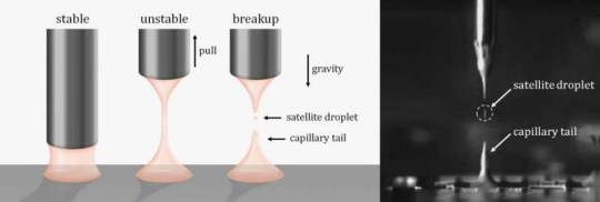
A new 'twist' to break viscoelastic liquid bridges
If you've ever tried to lift a pizza slice covered in hot, melted cheese, you've no doubt encountered the long, cheesy strings that bridge one pizza slice from the next. Keep lifting the pizza slice and these cheese bridges eventually break, covering the plate, table (or even your lap) in long, thin strands of cheese. While this is just a minor inconvenience with pizza, it is a longstanding problem in industry, where liquids with similar properties to melted cheese—dubbed viscoelastic fluids—need to be cleanly and speedily dispensed.
Now, scientists have developed a new technique that uses rotation to break these liquid bridges. Their findings, published 11 June 2021 in PNAS, could improve the speed and precision of dispensing viscoelastic fluids, in applications ranging from circuit board production and food processing to live tissue engineering and 3D printing.
"Viscoelastic fluids, like ketchup, silly putty and toothpaste, have very strange properties—when squeezed slowly, they flow like a fluid, but at faster speeds, they act like an elastic solid," said co-first author, San To Chan, who is a Ph.D. student and JSPS DC2 Fellow in the Micro/Bio/Nanofluidics Unit at the Okinawa Institute of Science and Technology Graduate University (OIST). "These unique properties make dispensing these fluids quite difficult."
Read more.
39 notes
·
View notes
Text
再谈流变学的振荡剪切测试方法
我在2009年,还是博士生的时候,在这里发表过关于Wladimir Philippoff的文章,标题是一个问答:《谁最先对材料施加正弦形变?W. Philippoff。》当时我很有自信,这个答���是对的。 流变学的先驱之一R. Bird和大幅振荡剪切的主要推广者A. Giacomin在2012年发表过一个有关类似���题的文章:谁先构思“复数粘度”的 。答案是另一位学者Andrew Gemant。 我前几年曾认真回顾过粘弹性研究的历史。可以说,人们对材料的粘弹性的认识,在最初的时候(Weber…
View On WordPress
1 note
·
View note
Text
Investigation of Extensional Flow Behavior of Polyethylene Melts through Birefringence by using Extrusion Cross-slot Die

Abstract
Flow parameters of polymers melt under steady state condition in shear are required to assess flow behaviour of the molten material in the die or downstream operations. Very often this is not sufficient to have a full understanding of the polymer processability, and additional information of flow response in extension is also needed. In this paper, the extensional properties of two molten polyethylene have been investigated by measuring stress response when a high extensional deformation is applied in a cross-slot die. Flow induced birefringence analysis and stress-optical rule are applied to determine rheological properties. Two polyethylene’s with similar rheology in shear but different molecular structure (HDPE and LLDPE) are analysed. Very interestingly, this approach appears capable of capturing differences in extensional flow that are not detectable using other conventional analytical methods.
Keywords: Flow Birefringence; Stress Optical Rule; Extensional Flow; Extensional Rheometry; Viscoelasticity
Introduction
Viscoelastic responses in shear and extensional regime of polymer melts are of paramount importance as they dominate most of the processing of polymers in the molten state [1]. Therefore, in industrial field, knowledge of rheology of polymers plays a central role in designing and understanding many processing operations: extrusion, blow molding, cast-blow extrusion, injection molding [2,3]. Specifically, extensional flow al high strain rate (ε ̇) is easily encountered in many industrial processes and there is increasing demand for generating more information about it [4]. It is usually more difficult to characterise properties of extensional flow than for simple shear. This kind of flow is commonly achieved with rheometers designed to uniaxially stretch the material. They typically include filament stretching [5] and dual wind-up stretching device [6]. However, true steady-state flow conditions are quite often difficult or impossible to reach because unlimited deformation is theoretically required [7], whereas elongational test is prone to sample inhomogeneity (due to localized necking) and rupture [8,9]. Gravity and non-isothermal condition on the sample, if the test is not carried out in climatic chamber or in thermostatic fluid, conspire to add limitation with these approaches. In many cases, when materials need to be tested at relative high temperature and broad strain rate close to effective industrial processing conditions, conventional lab-scale approaches in extensional flow with existing stretching rheometers are not capable to fully provide the required information. Low melt strength or sagging of molten materials promote premature deformation of the specimen, forcing to carrying out test at lower temperatures and it is not representative of real process conditions. This can limit the usage of conventional devices and methods. Therefore, there are relatively few data available for extensional flow [10] and especially for low viscosity molten polymers, measurements are very often overlooked and sometimes results are an over-simplification of real behavior.
For these reasons, full characterization of true steady state value for extensional stress response over a broad range strain rates is still an open topic in the field of polymer melts. In this scenario, cross-slot die, and rheo-optical approach appear to be a valid tool to get insight into rheology of complex flow and mimic and capture more closely extensional flow typically encountered in industrial operations [11,12]. Specifically, rheo-optical method offers potential to explore and evaluate the spatial-temporal evolution of the stress response of polymer melts [13]. It is an elegant and non-invasive way to generate extensional flow in controlled environment and confined geometries (the cross-slot die), it is well suited for polymer melts with poor melt strength, and/or non-homogeneous deformation at relatively high Henky strain or in case of not-achievement of a robust steady state [14]. Lastly, extensional flow can be sustained indefinitely in long run. This is possible through the connection of flow cell to a couple of extruders that provide a continuous feed of molten polymers up to relatively high flow rate. Thanks to the execution of the test in confined geometries, the method is insensitive to problems of melt yielding and high fluidity that, on the contrary, could make problematic the use of current rheometers operating in “not confined” environment. The specific geometry of the crossslot used in these experiments provides, for material transiting close to the stagnation point, high planar extensional flow that propagates along the entire plane of symmetry toward the outlet, which results in high level of extensional rate. Flow induced birefringence measurement (FIB) is used to evaluate interaction of the light with the polymer melt flow. Moreover the birefringence property is related to the stress distribution, polymer chains orientation and stretching with respect to stress directions.
Stresses in the melt stream were evaluated and quantified from flow-induced-birefringence (FIB) pattern along the centerline using the stress optical rule (SOR). It is well known that there exists, under a wide variety of conditions, a constant in the ratio of birefringence n and stress σ and is expressed as:
Where SOC is the stress optical coefficient for the polymers under analysis. It is given in unit of Pa-1. For the work presented in this paper a SOC of 1,80 x 10⁻⁹ Pa-1 is used for HDPE and LLDPE, which is in good agreement with the range given in literature for PE from 1,2 to 2,4 x10⁻⁹ Pa-1 [15,16]. Stress-optical rule has been found to remain linear in a wide stress range [17] and SOC weakly dependent on temperature [17,18]. The main goal of this paper is to investigate if melt flow induced stress birefringence can capture and well allow distinction of the behavior in extensional flow of the two polymers, otherwise not distinguishable with conventional rheological techniques. At the same time, we want to verify how sensitive the method is to capture differences in behaviour due to branching.
Materials and Experimental Setups
Materials
Materials used in this paper are a linear HDPE (Eraclene ML70U) and LLPDE (Clearflex CLD0) produced by Versalis, both with a very similar melt flow index. The first one is designed for extrusion application, whereas the second one is more suitable for injection moulding and film processes. They have very different degree of branching but despite this different molecular structure and application, still exhibit similar shear viscosity (Table 1).
Material Characterization in Shear Flow
The viscoelastic behaviour of two polyethylene samples has been evaluated in shear capillary experiment and by dynamic analysis. Results are reported in Table 1 and in Figure 1 (Master Curves). The grades have been selected because have very similar shear viscosity and master curve but very different degree of branching. It must be pointed out that both PE’s grades, neither elongational viscosity test nor fiber melt spinning measurements can be performed, due to the very low melt strength and sagging of the polymers at high temperature. Oscillating shear capillary rheometry (OSCAR) [19] has been also used to assess the complex rheology of LLDPE and of HDPE. The behaviour of the elastic modulus was measured at 190 °C for a shear cycle of period p=180s and amplitude . The elastic shear modulus reaches almost the same low shear rate value of 0.12 MPa for both PE but shows a plateau only for the HDPE up to 200 s-1 while for the LLDPE it keeps constantly decreasing within the same range of shear. It is also important to report that the shear viscosity modulus V(γ ̇) for both samples is perfectly superimposable.The elastic shear modulus behaviour can give some explanation to the industrial evidence on why the LLDPE is not suitable for extrusion production due to the inconsistency of its melt strength, also providing an explanation on why those polymers are not suitable for the same transformation process. Unfortunately, this approach requires a dedicated instrument with a very time-consuming experimental approach. In this work we have investigated the extensional viscosity at high ε ̇ rate of strain to fully access the rheological response of both material in many industrial processes.
Experimental Set Up
Equipment used for flow induced birefringence (from now on named as FIB) experiments is called “GEMINA”. It was designed and manufactured by Isotattica [20]. It basically consists of a couple of extruders and a patent pending cross-slot die including an optical bench for flow visualization.
Single screw extruders
To obtain a continuous flow of molten polymer to be delivered to the cross-slot die, the two independent-controlled extruders are coupled with the cross-slot apparatus. Each extruder is equipped with a 30 mm barrel/screw diameter and a L/D ratio of 25. Each of them is heated by three electrically powered zones on the barrel, a fourth one on the flange and a fifth one on die. It is powered by a 4 kW electric motor with a drive gear and electronic speed controller. Experiments are carried out at three different melt temperatures: 160, 190 and 220 °C, the extents of this range has been chosen in order to reproduce typical situations of use in machining processes. Pellets of polymers are feed in the hopper and molten polymer is transported along the extruder into the die. Setting temperatures from hopper to the die are selected in such way to get an effective temperature of the molten polymers as indicated above. Flow visualization experiments were performed after waiting for a certain time (15 min) for extruder parameters stabilization. Typical data collected for each run are as follows: flow rate, video and picture capturing for subsequent sequencing and processing via FIB. The range of flow rate used for experiments is from 20 cm3/min up to 290 cm3/min (i.e. from 16 s-1 to 225 s-1 in terms of apparent shear rates near inlet flow passageway).
Cross-slot die
A modular cross-slot die is fitted at the extruders exit from when the molten polymers flow. The cross-slot geometry provides four perpendicular, intersecting coplanar channels (width 4 mm, channel depth 8 mm), rounded at intersection point (Figure 2). The flow involves two opposed inlet streams which lies on the same axis meeting at a planar stagnation point and then exit orthogonally. It has a pair of stress-free transparent viewing windows (borosilicate glass) that allows a light beam to pass through the midsection of flow field and orthogonal analyzer before being captured using a digital video camera. The entire die is heated with electric heaters deeply inserted in the die, then connected with two independent temperature probe and controlled by the two zones 5B of the extruder panel control. The die is also equipped with 4 thread holes, in the passageway between adapters and cross die, for inserting melt pressure transducer or temperature probe (flush mounted). The two molten polymers are extruded with controlled flow rate and temperature in opposite directions towards the centre along the opposing collinear flow channels. By impinging these two fluids, flow induced stress birefringence is generated, allowing visualization and mapping of stress fringes, that correspond to a locus of constant value of principal stress differences PSD. Largestrain extensional flow deformations, preferred alignments and stagnation flow are generated along the inlet-outlet symmetry plane of the collinear channels and then analysed via flow-induced birefringence.
Optical bench
The flow birefringence measurements are performed using an optical bench as shown schematically in Figure 3. From top to the bottom, it consists of light source (white light), polarizer, two quarter wave plate (the cross-slot die is placed between them), analyser, extension tube with camera lens, and digital video camera. Firstly, the light beam passes the polarizer and quarter wave pate, enter through glass windows the melt stream which rotates its polarization state, then exit through the other glass window, quarter wave plate and analyser before reaching video camera. With this arrangement polarization of light is circular (circular polariscope in dark or bright field), isoclinic extinction bands (loci of points where principal stresses directions are constant) are not visible, leaving only stress-related isochromatic fringes (loci of points where the difference of principal normal stresses is constant). The optical parts are designed for fast assembly on a stand, are mechanically independent and moveable in all three dimensions for precise tuning of each component. Additionally, said stand, after competition of runs, can be moved away from die housing and extruders. With white light, coloured bands are observed, they are called “isochromatic fringes”. Firstly, fringe tracking and fringe order assignment are done. Considering that each isochromatic fringe with same colour carries the same light retardation and corresponds to a constant value of principal stress difference, the latter can be quantified through the stress optical rule.
The most important relation that allows us to calculate the PSD is given below:
Here N is the fringe order, l is the wavelength of light, d the channel depth. Combining stress optical rule (Equation 1) and Equation 2 it is possible to calculate the PSD by determining birefringence in molten flow on each isochromatic fringe.
Results and Discussion
Elongational flow/FIB
In the symmetry plane inlet-outlet along the centreline, at steady state regime, polymer flow experiences a constant extension rate ε̇. It can be estimated by the formula:
Where Vavg is the average velocity in the passageway and w the channel width. In this area flow approaches fully developed planar stretching flow. The steady state elongational viscosity is calculated from tensile stress (σstd is the PSD-principal stress difference between X-extensional and y-compressional axes, determined by FIB analysis) and the steady state strain rate ε̇ (Equation 4):
The evolution of the fringes as function of flow rate indicates a progressive increase of level of anisotropy between inlet and outlet channels (Figure 4). The isochromatic fringes of the birefringence are used to determine the principal stress difference in steadystate condition: each fringe carries a fixed stress contribution and through fringe sequencing and assignment of fringe order along the exit symmetry plane (fringe counting technique) is possible to determine PSD. An increase on concentration of isochromatic fringes is observed at high flow rate, mainly located along the exit symmetry plane where stretching flow is supposed to be fully developed. Quantitative representation of stress build-up versus extension rate is well illustrated in Figure 5. The graph corresponds to steady state conditions of fringe patterns. It is observed that the difference in stress between HDPE and LLDPE is maintained throughout the extended range of extension rate investigated. For both materials, the level of stress anisotropy between inlet and outlet channel flow increases as flowrates increase. The difference in stress concentration leads finally to a different evolution of extensional viscosity vs extension rate (Figure 6). The effect of difference in structure between HDPE and LLDPE is also well illustrated in Figure 7 & 8. The differences in fringe numbers sequencing made at same level of extensional rate are representative of the polymer type. LLDPE (short chain branching) shows the lower level on center-line stress fringes on comparison to HDPE (extensive branching), thus indicating for the former a lower stress concentration localized in the area of outlet symmetry plane.
As explained above, the configuration of the optical train used for the evaluations (circular polarization) is such as to examine isochromatic fringes. We have mentioned that with a different optical setup (linear polarization in dark field) is possible to also evaluate the isocline bands, loci of points where principal stresses directions are constant. With this configuration the initial field is dark, the principal stresses on melt produce a pattern of coloured fringes that vary with loading (isochromatic), on the same time some dark bands remain fixed with stress (isoclines); by rotating the polariser and analyser together, the coloured fringes do not vary (isochromatic) while the dark fringes change (clearly detectable isoclines). It has been made an exploratory survey and it has provided an interesting mapping of their distribution (Figure 9). Isoclinic fringes of HDPE are practically superimposable to those of LLDPE, an indicator that materials express a similar spatial orientation of stresses. There are some points which remain dark during simultaneous rotation, they are called singular points (S1 and S2) where both principal stresses are equal and hence σ1 = σ2 or σ1 – σ2 = 0. If σ1 = σ2 they represent fringe order 0 (black colour) in isochromatic evaluation. Isoclinic fringes allow, through a subsequent graphic elaboration, to determine the so-called isostatics which are the trajectories of the stresses. However, this issue is not the subject of this investigation, it will be addressed in future studies.
Summary and Conclusion
The cross-slot device coupled with two extruders allows measurement of steady-state planar extensional viscosity in a broad strain rate regime through stress birefringence. Specifically, the properties of two polyethylenes under extensional flow have been assessed by using this non-invasive rheo-optical approach. This analysis show how steady-state extensional flow can be evaluated through cross-slot measurement and how different branching in the molecular structure has an impact on stress in elongational flow. The PSD at different level of strain rate was captured using flow-induced birefringence. The PSD pattern developed from an initial near-Newtonian response (slow flow, quasi symmetric pattern between inlet and outlet) to gradually increasing level of asymmetry between inlet and outlet flow as the flow rate increases (stretching flow). It has been experimentally verified that these two materials show a difference in extensional viscosity, and the presence of long chain branches in the molecular morphology in HDPE affects the stress in extensional flow. On the other hand, LLDPE shows a lower extensional viscosity. The advantage of this method lies in the possibility to replicate the same temperature of industrial process and extensional optical device has confined geometry that allows the testing on molten polymers that, due their poor melt strength, sagging, localized necking at test temperature, cannot be otherwise tested in free-surface devices (not-confined geometries) like current commercial stretching rheometers.
Additionally, high strain steady-state limit can also be reached in long stable extrusion run. According to our findings, this approach is capable to detect and differentiate extensional rheology of different polymers that would not otherwise be captured with other techniques Cross slot die and rheo-optical analysis does have some limitations. At high stress values, fringes stratification become very high and the sequencing and counting may be more demanding. The PSD patterns for HDPE show a higher level of stress vs LLDPE at same strain rate, and it is observed that sequence of patterns of HDPE is always approximately two levels of fringe orders more forward than the LDPE compared at same level on central extension rate. The difference in growing number of fringes for HDPE versus LLDPE ultimately lead to a different extensional viscosity response. It should be remembered that these two materials have very similar shear viscosity and mater curve, despite significant different degree of branching is present. On the same time the differentiation observed in extensional viscosity is in good qualitative agreement with mechanical behaviour - elastic shear modulus under shear flow - performed via-OSCAR technique. Results obtained with these two techniques corroborate the explanation of the different evidence of extensional behaviour of these two polyethylenes. This also reflected in the industrial field: HDPE is more suitable for extrusion than LLDPE.
The design of the die inevitably leads to a compromise in relation to channel dimension and aspect ratio. Ideally twodimensional flow is desirable, even if an increase in branching enhance localized three-dimensional flow with stress pattern increasingly asymmetric. In conclusion, it has been shown that rheo-optical approach with flow induced birefringence analysis can be used for mapping and measuring properties of melts in extension along the plane of the outlet channels, or simultaneously shear properties in the inlet channels as well, depending on geometry of die, thus providing to be a very useful and intriguing tool to capture the smallest differences in flow behaviour and assess polymer performances. This methodology can become an indicator of rarely observed phenomenon that are not made manifest with conventional approaches and/or non-fully predict with simulation. It can be seen as a complementary approach to current extensional rheometers, towards which it strengthens the measuring range, provides kinematically steady extensional flow, exceeds their limits in maximum allowable testing temperature and applicable extension rate. The connection of the rheooptical die with extruders also guarantees a constant support of homogeneous molten material to the flow cell and above all a long and stable test duration. Lastly, this kind of lay out (cross-slot die and extruder coupling) makes this equipment quite innovative among the available equipment for industrial rheology. It can be used with the purpose of quality control, polymer and compounds design, R&D and optimization in tooling designing.
Future Works
Rheo-optic analysis with cross-slot die coupled with extruders is certainly a field of investigation still to be fully exploited. Further tests with polymers different from each other or belonging to the same monomeric identity but different molecular architecture are to be encouraged, making the most of the potential of the flow-induced birefringence. New potential field of study is certainly the evaluation of isoclines, in parallel to birefringence analysis of isochromatic. Isotropic points appearing in low fringe order zones are often either overlooked or entirely missed in conventional rheo-optical analysis. Vice versa, isoclines and especially their processing into isostatics, could provide complementary information to understand the stress trajectories in flowing materials. This will be the subject of a future work.
For more Open Access Journals in Juniper Publishers please click on: https://juniperpublishers.com/
For more articles in Academic Journal of Polymer Science please click on: https://juniperpublishers.com/ajop/index.php
0 notes
Text
Investigation of the Boundary Layer Blood Flow and the Initial Factors of Atherosclerosis by the Magnetic Resonance Imaging | Chapter 03 | Emerging Research in Medical Sciences Vol. 2
Aim: study the blood flow and vessel wall viscoelastic alterations at the boundary layer and initial factors of atherosclerosis.
Study Design: Magnetic resonance angiography with the follow up flow quantification was carried out voluntary on the healthy persons.
Place and Duration of Study: MRI department of the Institute of Clinical Medicine in Tbilisi Rep. Georgia, between September 2012 and July 2017.
Methodology: In 12 healthy men (18-52 years of age) at the different sites of the aorta peak velocity, net flow, flow acceleration has been investigated by Magnetic Resonance Angiography. Blood radiodensity (HU) were studied (CT) in different sites of the aorta and vena cava.
Results: In the aortic arch in the end systole blood flow separates into the opposite directed streams resulting in the wave superposition. At the outer curvature of the isthmus, flow acceleration in the initial diastole is 6.26 times higher than that in systole. Net flow from systole to diastole increases 2.5±0.5 folds. From the end systole to the initial diastole there is a plateau on the net flow graph. At the outer curvature of isthmus, group wave at the boundary reflection, changes in phase at 180°. At the same time flow wave oscillation frequency at the outer curvature is two times higher (1.6Hz.) than that at the inner (0.8Hz).
Conclusion: During the heart cycle, blood motion at the boundary layer, forms the surface wave and facilitates the blood structural rearrangement and flow. At the end systole, at the outer curvature of the isthmus, pulse pressure at the reflection is in the resonance with the end systolic pressure drop. Amplitude of the wall stress increases. Forming standing wave leads to the dissipation of the wall’s mechanical energy. Here, at the initial diastole, group wave, due to the wave reflection, and frequency dispersion, facilitates to the structural rearrangement/denudation of the vessel wall.
Author(s) Details
M. Beraia MRI Department, Institute of Clinical Medicine. 13 Tevdore Mgvdeli str. 0112. Tbilisi, Georgia.
G. Beraia Medical student (B.S.) Tbilisi State Medical University. 33 Vazha-Phshavela ave. 0177. Tbilisi. Georgia.
View Books: http://bp.bookpi.org/index.php/bpi/catalog/book/92
0 notes
Photo

You may have noticed when baking that fluids don’t always behave as expected when you agitate them. If you put a spinning rod into a fluid, we’d expect the rod to fling fluid away, creating a little vortex that stirs everything around. And for a typical (Newtonian) fluid, this is what we see. The fluid’s viscosity tries to resist deforming the fluid, but the momentum imparted by the rod wins out. With a viscoelastic fluid, on the other hand, the story is much different. As before, the spinning of the rod deforms the fluid. But the viscoelastic fluid contains long chains of polymers. As those polymers get stretched by the deformation, they generate their own forces, including forces parallel to the rod. Instead of being flung outward, the viscoelastic fluid starts climbing up the rod, with the stretchy elasticity of the polymers helping pull more fluid up and up. (Image credit: Ewoldt Research Group, source)
#fluid dynamics#science#physics#viscoelasticity#viscous flow#Newtonian fluid#non-Newtonian fluid#polymer effects#Weissenberg effect
1K notes
·
View notes
Text
惯量与粘弹性
[latexpage] 最近为了搞清楚仪器的测量极限,和学生一起考虑了一通仪器惯量的问题。结果这一考虑就是几个月。…
View On WordPress
0 notes
Text
Effects of Nanoparticles on Rheological Behavior of Polyacrylamide Related to Enhance Oil Recovery-Juniper Publishers
JUNIPER PUBLISHERS- ACADEMIC JOURNAL OF POLYMER SCIENCE
Abstract
The effect of nanoparticles SiO2, TiO2 and Fe2O3 on the rheological behavior of anionic polyacrylamide and a mixed assembly of polymer and cationic surfactants were measured systematically by shear viscosity and oscillatory testing at different concentration of Nano-materials. The results of shear viscosity measurement indicate that for all of the systems, the shear viscosity increases with the addition of nanoparticles and show shear thinning behavior at low shear rate. In the oscillatory test, all of the systems show elastic behavior, which depend on the concentration of nanoparticles. The storage modulus (G’) and loss modulus (G’’) increased as nanoparticles concentration increase. The core flooding experiment were also done with polymer-surfactant solution in presence and absence of nanoparticles and the obtained result indicates the higher oil recovery in presence of nanomaterials. In enhance oil recovery process; the viscosity and viscoelasticity are key parameters for the success of the recovery process.
Keywords: Wettability; Viscoelasticity; Displacement efficiency; Nanoparticles
Introduction
Due to the increasing demand of energy and diminishing amount of conventional oil, the oil industries have been relying on enhanced oil recovery methods for decades. Presently, lots of researches are being carried out globally to improve enhanced oil recovery techniques to fulfill the demands of oil. Recently, the use of nanoparticles in enhance oil recovery has been proved very efficient. With a nano size and large surface area to volume ratio, nanoparticles have the potential to penetrate the pores in the reservoir rocks where conventional enhance oil recovery process are unable to. The nanoparticles can alter the oil reservoir characteristics such as mobility ratio, wettability, interfacial tension, injected fluid viscosity and are stable than the polymer-surfactant at harsh and saline conditions [1-3]. The oil recovery decreases by increasing the salt concentration during the polymer flooding, whereas in the case of flooding with a suspension of nano-silica in the polymer, decreasing the rate of oil recovery is lower [4]. The nanoparticles are more capable of the reduction of interfacial tension and the alteration of wettability in the case of light oil reservoir [5].
In the last decade, nanoparticles have attracted many researcher’s attention in the field of enhance oil recovery due to their unique properties. Maghzi et al., [6] reported that at the same salinity, the oil recovery is 10% higher with nanoparticles than the polymer flooding in the absence of nanoparticles. Hu et al., [7] reported that with 5ppm concentration of nanoparticles recovered the original oil in place about 35.8%, with 10ppm of nanoparticles it is 41.8% and with 20ppm of nanoparticles, 39.8% of original oil in place was recovered. At low nanoparticles concentrations, the rate of recovery of oil increases with an increase of nanoparticles concentration and reaching a peak value at 20ppm, above which it starts to decline.
Joonaki et al., [8] reported in his result, the total oil recovery by using nanoparticles is 92.5%, 88.6% and 95.3% in the three scenarios. This result indicates that the oil recovery will be higher, and less amount of oil is remaining trapped within the porous media, if the nano fluid injection begins earlier. In the experiment of Pei et al., [9], 50% of the OOIP were recovered with silica nanoparticles. These results demonstrate that the injection of nanoparticles with polymer and surfactant system can significantly increase the wettability, reduce the mobility ratio and thus leads to the improvement of enhance oil recovery. Yousefvand et al., [10] reported in his paper that the oil recovery factor after one pore volume of the injected fluid has been obtained and results indicate that in the presence of nano silica an improvement about 10% in the ultimate oil recovery can be achieved and this is due to the viscosity enhancement of the injected fluid. Also, nanoparticles have ability to change the wettability to water-wet in some portions of the micro model.
In this study, we have organized a series of experiments to know the potential effects of nano-materials on the rheological behavior of polyacrylamide solution. The sample viscosities in different concentrations of nanoparticles, shear rates, temperature were measured. Because the viscosity plays a very important role in enhance oil recovery. Also, this paper presents a comparison between the effects of different nanoparticles on the rheology of polyacrylamide in the presence of surfactants. In addition, the viscoelasticity of polyacrylamide solution in the presence of different nanoparticles was also measured.
Procedure
Materials
For this study, polyacrylamide (PAM) of molecular weight 150000, was purchased from Sigma Aldrich, U.S.A. CTAB surfactant (≥99.0%, Merck, Germany) was used as received. Gemini surfactants α,ω- bis (hexadecyldimethylammonium) alkane dibromides (16-6-16 and 16-5-16) were prepared and purified. Also, three types of nanoparticles were used for this study. These nanoparticles are Silica fumes (particle size 0.007μm, specific surface area 395 ± 25m2/g, density 36.8424649kg/m3), TiO2 (particle size < 100nm, purity 99.5% trace metal basis, specific surface area 50 -100nm) and Fe2O3 (particle size 50- 100nm, purity 97% trace metal basis, specific surface area 40- 60m2/g) was purchased from Sigma Aldrich, St. Lucia, U.S.A. All the experiments were conducted at 50 °C and all the solution was prepared in double distilled water (Table 1).
Preparation of solution
The polymer solution of 1.0wt% concentration was prepared in distilled water. The nanoparticle of SiO2, TiO2, Fe2O3 in a concentration of 0.2wt% to 1.0wt% was mixed with polyacrylamide solution. After conducting several tests of polymer and nanoparticle mixture, we add cationic surfactants with these solutions. It is also observed that above 1.0wt% of a nanoparticle of SiO2 and TiO2 (except Fe2O3), the solution of polymer and Gemini surfactants gets precipitated. This will set the limit and we add the nanoparticle at low concentration very carefully. The solutions of polymer-surfactant-nanoparticle are not easily mixed with each other and the solution will require a heating and agitation for several hours.
Methods
There is a wide range of rheological measurement techniques are available and each one has its advantages and disadvantages. To maximize the value of the data generated it is obviously important to ensure that the most appropriate technique is used for the application. The shear viscosity of the prepared solution as a function of shear rate and concentration were measured using Anton Paar’s Modular Compact Rheometer (series 102) with cone shaped measuring geometry at 50°C. The shear viscosity at all solution concentrations, over a shear rate range of 0 to 500s- 1 was measured. The oscillatory frequency test was also carried out at an angular frequency of 0.1 to 100 rad. s-1. Generally, the oscillatory tests were carried out to determine the viscoelastic behavior of the solution.
Core flooding experiment were performed to measure the recovery of crude oil by using sand pack system. The crude oil was obtained from Rajasthan oil field, India with API of 19.2 at 28 °C. The sandstone with the permeability of 2.5 milli Darcy and porosity 0.19 was used for the test. During the test, the sand pack was flooded with crude oil at 30psig. Then, the polymer-surfactant and polymer-surfactant-nanoparticle solution was introduced in a sand pack when water cut exceeded 95%.
Results and Discussion
Effect of different concentration of nanoparticles on viscosity
The rheological properties of the injected fluid are an important parameter in a chemical flooding process. The additional increase in viscosity of injected fluid, the oil displacement efficiency is increased, and more oil recovered from the porous rock. To observe the effect of silica nanoparticles on the viscosity of polymer solution, the viscosity measurement test was performed with 1.0 wt.% of a polymer solution and also with polymersurfactants system containing different silica concentration at 50 0C. From a Figure 1, the viscosity of polymer solution increases with increase in a concentration of Nano-silica. The ion-dipole interaction is developed between cations and oxygen atoms in the tetrahedral structure of silica. Thus, the attack of cations to polymer molecules is reduced to some extent and the increase in viscosity of the solution is observed in the presence of silica nanoparticles. Consequently, the oil recovery increases during chemical flooding test by increasing the silica nanoparticles concentration [4].
The same effect of nano-TiO2 and nano-Fe2O3 on the rheology of polyacrylamide was also obtained at the same operating conditions (Figure 2&3). The viscosity of the polymer increases with increase in the concentration of nano-TiO2 and nano-Fe2O3 as expected. But there is a more drastic change in the viscosity of polyacrylamide is observed with the nano- materials of metal oxides. TiO2 shows the ability to provide much better result in enhance oil recovery process while chemical flooding. Comparing with the nano-silica, the nano- TiO2 increases the viscosity of polymer solution up to 83.33% and the nano-Fe2O3 increases the viscosity of about 64.28%. Also, some research studies suggested that the reduction of oil viscosity is possible via nanoparticles of metals oxide. A Bayat et al., [11] reported in his work, that SiO2, TiO2, Al2O3 and nano-fluids flooding at 60 ͦC caused 8, 24 and 34% viscosity reduction compared to the original oil viscosity at the same temperature, respectively. This is because TiO2, Al2O3 and Fe2O3 have higher thermal conductivity than SiO2.
The effect of nanoparticles on the mixed assembly of polymer and surfactant are shown in Figure 4,5 and 6. The concentration of polymer and surfactants are fixed and the test was conducted at 50 0C. The shear viscosity of all the systems increases with nanosilica concentration. As shown in Figure 4, the polymer solution with CTAB surfactant shows a more drastic change in the viscosity with a given Nano-silica concentration range. In a case of TiO2 and Fe2O3, the Gemini (16-5-16) surfactant shows more effect on the rheological property of polyacrylamide. The interaction between the polymer and nanoparticles are affected by the presence of a surfactant (Figure 5&6). The surfactants in the solution can dislocate and relocate on the surface of the nanomaterial and ultimately created new surfactant coated particles. This will lead to increase in the viscosity of the solution.
Effect of shear on the rheological properties of the polymer-nanoparticles and polymer-surfactant-nanoparticles hybrid system
In this section, the effects of shear rate on the viscosity of polymer-nanoparticles and polymer-surfactant-nanoparticles hybrid system were studied. The results are plotted in Figure 7, 8 and 9 for a fixed PAM concentration of 0.5 wt.% with varying concentration of nano-Si, nano-TiO2 and nano-Fe2O3 from 0.5 to 1.0 wt.%. The results indicate that the addition of nanoparticles in the polyacrylamide solution leads to increase in viscosity. Because of the irreversible adsorption of polyacrylamide on nanoparticles, the resultant macro-molecular structure is stable and not easily broken, and it leads to increase in viscosity of the system. The viscosity of polymer-nanomaterial system is greater than the viscosity of polyacrylamide solution at same temperature and shear rate. Figure 10, 11 and 12 shows the viscosity variation of polymer-surfactant-nanoparticles hybrid system. Across all the polymer, surfactants and nanoparticles concentrations, it is found that the samples revealed non-Newtonian shear thinning behavior at low shear rate (γ < 25 s-1). But at high shear rate the solution loses it’s non-Newtonian and shows shear thickening behavior [12]. At low shear rate, the viscosity of the system is obviously dropped. The bond between the polymer and nanoparticles are not easily broken in normal state, but progressively weakens as shear rate increases, thus the flow of the suspension is shear thinning [13]. The shear thinning behavior and incremental shear viscosity with concentration of polyacrylamide and nanoparticles can be responsible for strong interaction between polymer and nanoparticles.
On the basis of results, adding a small amount of nanoparticles can improve the pseudo-plasticity behavior of polymer solution at a given shear rate. From the above discussion, it is observed that the nano-suspension increases the viscosity of the solution in comparison to polymer viscosity. It indicates that the nanoparticles can increase the sweep efficiency of the polymer solution and oil recovery will be higher with nanoparticles. The more nanoparticles transportation will be the more effective the wettability alteration and better effective sweep efficiency of the polymer-surfactant solution.
Effect of nanoparticles on viscoelastic behavior of polymer
The viscoelastic properties of polymer solution are widely used to gain insight into structure strength of polymer in the solution. The viscoelastic property of polymer plays an important role in increasing the oil recovery. Larger the viscoelasticity, greater will be the sweep efficiency of the polymer solution. Figure 13 shows the plots of storage modulus (G’) as a function of oscillatory angular frequency (ω) for polyacrylamide solution and polymer-silica mixed system at 50 0C. For all the solutions, storage modulus G’ is a strong function of angular frequency and increases over the entire range. The elastic part of the polymer is called the storage modulus (G’) and it is a measure of the energy stored and recovered. The viscous part is called the loss modulus G” which is a measure of the energy dissipated [14]. The value of storage modulus increases with increases the concentration of nanoparticles due to the more numbers of nanoparticles available in the solution. With the addition of silica nanoparticles, storage modulus of polymer-silica system greater than that of the polyacrylamide solution. This indicates that the polyacrylamidenanosilica mixed system undergoes microstructural changes and they have ability to increase the oil recovery. In the polymersilica mixed system, the interaction between the amide group of polyacrylamide and silanol functional group of nano-silica occurred. So, the structure of polyacrylamide strengthened, and the elasticity of the mixed system becomes more pronounced. The elastic property is more dominant than the viscous i.e., G’ is greater than G’’. This indicates that there is a significant buildup of network structure that is responsible for imparting a significant elasticity to the polymer solutions [12].
Figure 14 shows the loss modulus (G’’) as a function of increasing angular frequency for PAM and PAM-silica mixed system. The loss modulus (G’’) is the characteristic of the viscous behaviors of the solution. When the value of storage modulus is greater than the loss modulus, it represents the solution exhibits viscoelastic gel like behavior and when the value of loss modulus is greater than storage modulus, the system displays a liquid like behavior. The value of G’ and G’’ increased with the angular frequency. On comparing the viscoelastic effect of nano-silica on polymer solution with TiO2 and Fe2O3 from Figure (15&17), the storage modulus (G’) of TiO2 is much larger than that of nano-Si and Fe2O3. G’ and G’’ increases with increase in a concentration of nanoparticles. The increase in a concentration of nanoparticles found to strengthen the network structure of polyacrylamide solution and this leads to increase the viscoelastic properties. At 1.0wt.% of TiO2, the flow curve is constant with the increase of angular frequency and G’ > G’’, this means the elastic effect is more dominant. The elastic behavior of all the above systems is more than that of loss modulus because the decreased friction at the polymer-nanoparticles interface led to the slight decrease in the loss modulus. From (Figure 16 & 18), the loss modulus is also increasing with the addition of nanoparticles, but the value of loss modulus is slightly less than the storage modulus at all concentration. Also, the value of loss modulus never exceeds to zero [15].
Core flooding Results
From Figure 19, the core flooding test was conducted by injecting a polymer and surfactant solution. First, the sandstone system saturated with the crude oil and then brine solution is injected to measure the porosity. The porosity of the sandstone system was found 0.19 or 19%. Then the crude oil was flooded with 30psi pressure. Brine solution is then injected in a sand pack system to displace the oil via secondary recovery and around 39% of oil is recovered. After that the polymer and surfactant solution were injected to recover the remaining oil as tertiary recovery. Additional recovery of 5.5%, 13.5%, and 17.3% were obtained for 1.0wt. PAM+50mmol CTAB, 1.0wt. PAM+50mmol G5 and 1.0wt. PAM+50 mmol G6 respectively. The polyacrylamide renders the mobility to the oil rich phase by increasing the viscosity of injected fluid. The crude oil droplets are mobilized by reducing the interfacial tension between the oil-water interfaces. As the spaces length of Gemini surfactant increases from 16-5-16 to 16-6-16, the crude oil saturation increases due to improved coalescing of mobilized crude oil droplets to form an oil bank and this result in better oil displacement and hence greater oil recovery. In presence of nanoparticles, the oil recovery percentage is improved as shown in Figure 20. The nanoparticles increase the viscosity of polymer solution significantly and this will lead to increase in storage modulus and loss modulus of polyacrylamide solution, results in the oil recovery will increase. The nano titanium oxide shows good result as compare to nano silica and nano iron oxide material.
Conclusion
In the present study, the rheological behavior of polyacrylamide and polymer-surfactant solution in the presence of nanoparticles was examined. The result reveals that the presence of nanoparticles strongly influences the rheological properties of solutions. It is found that the shear viscosity of polyacrylamide solution increased with the addition of nanoparticles. With the introduction of nanoparticles in the polymer solution, the polymer chains adsorb on the nanoparticles surface and complex micelle type structure is formed and this interaction leads to increase the viscosity, which indicates that increase in sweep efficiency. A non- Newtonian shear thinning behavior was observed at low shear rate (γ < 25s-1). The titanium oxide shows the promising prospects for potential application in enhance oil recovery. The addition of nanoparticles improves the viscoelastic properties of polymer. The additional 11.5%, 17.5% and 22% of oil recovery were observed in presence of nanoparticles. It means nano-suspension can be used in enhance oil recovery and more beneficial than chemical flooding without nanoparticles.
For more Open Access Journals in Juniper Publishers please click on: https://juniperpublishers.com
For more articles in Academic Journal of Polymer Science please click on: https://juniperpublishers.com/ajop/index.php
For more Open Access Journals please click on: https://juniperpublishers.com
0 notes
Text
An Introduction to Viscoelasticity Dynamic Mechanical Analysis

An Introduction to Viscoelasticity Dynamic Mechanical Analysis by ADMET CEO Richard Gedney Viscoelasticity is the property of a material that exhibits some combination of both elastic or spring-like and viscous or flow-like behavior. Dynamic mechanical analysis is carried out by applying a sinusoidally varying force to a test specimen and measuring the resulting strain response. Read the full article
0 notes
Photo

Adding just a few polymers to a liquid can substantially change its behavior. The presence of polymers turns otherwise Newtonian fluids like water into viscoelastic fluids. When deformed, viscoelastic fluids have a response that is part viscous--like other fluids--and part elastic--like a rubber band that regains its initial shape. The collage above shows what happens to a thinning column of a viscoelastic fluid. Instead of breaking into a stream of droplets, the liquid forms drop connected with a thin filament, like beads on a string. In a Newtonian fluid, surface tension would tend to break off the drops at their narrowest point, but stretching the polymers in the viscoelastic fluid provides just enough normal stress to keep the filament intact. If the effect looks familiar, it may be because you've seen it in the mirror. Human saliva is a viscoelastic liquid! (Image credit: A. Wagner et al.)
637 notes
·
View notes
Photo

3-D-printed robots with shock-absorbing skins
Anyone who's watched drone videos or an episode of "BattleBots" knows that robots can break -- and often it's because they don't have the proper padding to protect themselves.
But this week researchers at MIT's Computer Science and Artificial Intelligence Laboratory (CSAIL) will present a new method for 3-D printing soft materials that make robots safer and more precise in their movements -- and that could be used to improve the durability of drones, phones, shoes, helmets, and more.
The team's "programmable viscoelastic material" (PVM) technique allows users to program every single part of a 3D-printed object to the exact levels of stiffness and elasticity they want, depending on the task they need for it.
For example, after 3-D printing a cube robot that moves by bouncing, the researchers outfitted it with shock-absorbing "skins" that use only 1/250 the amount of energy it transfers to the ground.
Read more.
20 notes
·
View notes
Text
An Introduction to Viscoelasticity Dynamic Mechanical Analysis
Read the full article
0 notes
Photo


The hagfish is an eel-like creature that has not changed much in the past 300 million years in part because the hagfish is very good at escaping would-be predators. When attacked, the hagfish excretes mucins that combine with seawater to form slime. This gel-like viscoelastic fluid forms quickly and has some handy properties. For example, when stretched, the slime becomes extremely viscous. Many fish feed using a suction method, in which they thrust their jaws forward and enlarge their mouths to suck water and prey inside. This strong unidirectional flow stretches the slime, which thickens it and clogs the fish’s gills. Suddenly, the fish is much more concerned with being unable to breathe, allowing the hagfish to flee.
Being surrounded by all that slime could smother the hagfish, too, if it were not for another clever feature of the slime. When sheared, hagfish slime collapses, losing its viscosity. The hagfish actually ties itself in a knot to create this shear and slide the slime right off. (Image credit: V. Zintzen et al.; L. Böni et al., source)
476 notes
·
View notes
Photo
Predicting delayed instabilities in viscoelastic solids
It is presently challenging to determine the stability of viscoelastic structures since seemingly stable conformations may gradually creep (plastic deformation of a material under stress as a function of time) until their stability is lost. Although a discernable creeping effect does not necessarily lend to instability of viscoelastic solids, researchers are currently limited with numerical simulations to predict the future stability relative to theoretical predictive tools. In a new report on Science Advances, Erez Y. Urbach and Efi Efrati in physics and complex systems at the Weizmann Institute of Science, Israel, described viscoelastic solids through an evolving instantaneous reference metric to measure elastic strains. The transparent and intuitive methods derived in this work for incompressible viscoelastic solids reduced the question of future stability to static calculations alone. The team showed the predictive power of the approach by understanding the subtle mechanisms of delayed instability in thin elastomeric shells in order to demonstrate quantitative agreement with experiments.
Read more.
13 notes
·
View notes
Photo

Homemade spaghetti noodles exhibit a roughened surface that’s the result of viscoelastic behavior known as the sharkskin instability. It’s usually observed in the industrial extrusion of polymer plastics. In the case of spaghetti, the long, complex polymer molecules necessary for the instability come from the proteins in eggs. The characteristically rough surface of the extruded material is caused by the transition from flow through the die to air. Inside the die, friction from the walls exerts a strong shear force on the outer part of the fluid while the inner portion flows freely. When the material exits the die, the sudden lack of friction on the outer portion of the fluid causes it to accelerate to the same velocity as the middle of the flow. This acceleration stretches the polymers until they snap free of the die; after the strained polymers relax, the material keeps a rough, saw-tooth pattern. In industry, the sharkskin instability can be prevented by regulating temperature or flow speed. In the case of spaghetti, though, Modernist Cuisine suggests the roughness is desirable because it helps trap the pasta sauce. Bon appetit! (Image credit: Modernist Cuisine)
#fluid dynamics#science#physics#viscoelasticity#polymer effects#sharkskin instability#fluid instability#instability#extrusion
425 notes
·
View notes