#Voltage-Controlled Oscillator
Explore tagged Tumblr posts
Visit Tumblr Blog
Explore Tumblr blogs with no restrictions, modern design and the best experience.
Last Seen Tumblr Blogs


Fun Fact
In February 2021, Tumblr had 518.6 million blog accounts.
Text
How does a VCO differ from a traditional oscillator?
A Voltage-Controlled Oscillator (VCO) is like the cool, adaptable cousin of a traditional oscillator. While both generate waveforms like sine, square, or triangle waves, a VCO can change its frequency based on an input voltage. This feature makes it super useful in applications like frequency modulation (FM) synthesis in music or tuning circuits in radios.
Traditional oscillators, on the other hand, usually have a fixed frequency, meaning they stay at one pitch or rate. They're reliable and straightforward but lack the flexibility of a VCO. So, think of a VCO as the more dynamic option, ready to change its tune based on the voltage it receives!
0 notes
Text
https://www.futureelectronics.com/p/electromechanical--timing-devices--crystals/ecs-250-18-5px-ckm-tr-ecs-inc.-4171530
Watch crystal, Quartz crystal oscillator, Voltage signal, quartz resonator
CSM-7X Series 7.3728 MHz ±30 ppm 20 pF -10 to +70 °C SMT Quartz Crystal
#Frequency Control & Timing Devices#Crystals#ECS-250-18-5PX-CKM-TR#ECS Inc#Watch crystal#Quartz crystal oscillator#Voltage signal#quartz resonator#clock#low frequency oscillators#calculator#Microprocessor#frequency#digital watches
2 notes
·
View notes
Text
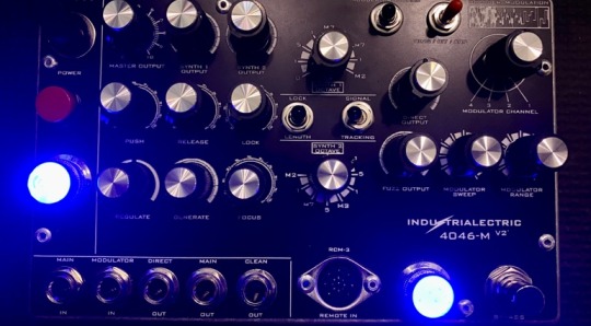
Industrialectric 4046-M VCO: Revamped V2 for 2024 announced
Industrialctric has just announced the return of its classic Voltage Controlled Oscillator (VCO), the 4046-M, now reimagined as the 4046-M (V2). This return comes in response to overwhelming customer demand, signifying a revival of a beloved product with enhanced features and functionality. Industrialectric 4046-M The 4046-M, renowned for its ability to accurately track and lock onto the phase…
View On WordPress
#4046-M (V2)#4046-M VCO#Boutique#footswitch#fuzz#Industrialectric#Industrialectric 4046-M VCO#modulation#NAMM#NAMM 2024#pedal#RCM-3#stomp#synth#VCO#Voltage Controlled Oscillator
0 notes
Text
Tesla’s Wardenclyffe Tower: Built on Sound Math, Undone by Cost and Misunderstanding

Let’s set the record straight—Nikola Tesla’s Wardenclyffe Tower was a high-voltage experimental transmission system grounded in quarter-wave resonance and electrostatic conduction—not Hertzian radiation. And the math behind it? It was solid—just often misunderstood by people applying the wrong physics.
In May 1901, Tesla calculated that to set the Earth into electrical resonance, he needed a quarter-wavelength system with a total conductor length of about 225,000 cm, or 738 feet.
So Tesla’s tower design had to evolve during construction. In a letter dated September 13, 1901, to architect Stanford White, Tesla wrote: “We cannot build that tower as outlined.” He scaled the visible height down to 200 feet. The final structure—based on photographic evidence and Tesla’s own testimony—stood at approximately 187 feet above ground. To meet the required electrical length, Tesla engineered a system that combined spiral coil geometry, an elevated terminal, a 120-foot vertical shaft extending underground, and radial pipes buried outward for approximately 300 feet. This subterranean network, together with the 187-foot tower and carefully tuned inductance, formed a continuous resonant conductor that matched Tesla’s target of 738 feet. He described this strategy in his 1897 patent (No. 593,138) and expanded on it in his 1900 and 1914 patents, showing how to simulate a longer conductor using high-frequency, resonant components. Even with a reduced visible height, Tesla’s system achieved quarter-wave resonance by completing the rest underground—proving that the tower’s electrical length, not its physical height, was what really mattered.
Tesla calculated his voltages to be around 10 million statvolts (roughly 3.3 billion volts in modern SI), so he had to consider corona discharge and dielectric breakdown. That’s why the terminal was designed with large, smooth spherical surfaces—to minimize electric surface density and reduce energy loss. This was no afterthought; it’s a core feature of his 1914 patent and clearly illustrated in his design sketches.
Now, about that ±16 volt swing across the Earth—what was Tesla talking about?
He modeled the Earth as a conductive sphere with a known electrostatic capacity. Using the relation:
ε × P = C × p
Where:
ε is the terminal’s capacitance (estimated at 1,000 cm)
P is the applied voltage (10⁷ statvolts)
C is the Earth’s capacitance, which Tesla estimated at 5.724 × 10⁸ cm (based on the Earth’s size)
p is the resulting voltage swing across the Earth
Plugging in the numbers gives p ≈ 17.5 volts, which Tesla rounded to ±16 volts. That’s a theoretical 32-volt peak-to-peak swing globally—not a trivial claim, but one rooted in his framework.
Modern recalculations, based on updated geophysical models, suggest a smaller swing—closer to ±7 volts—using a revised Earth capacitance of about 7.1 × 10⁸ cm. But that’s not a knock on Tesla’s math. His original ±16V estimate was fully consistent with the cgs system and the best data available in 1901, where the Earth was treated as a uniformly conductive sphere.
The difference between 7 and 16 volts isn’t about wrong numbers—it’s about evolving assumptions. Tesla wrote the equation. Others just adjusted the inputs. His premise—that the Earth could be set into controlled electrical resonance—still stands. Even if the voltage swing changes. The vision didn’t.
Wouldn't that ±16V swing affect nature or people? Not directly. It wasn’t a shock or discharge—it was a global oscillation in Earth’s electric potential, spread evenly across vast distances. The voltage gradient would be tiny at any given point—far less than what’s generated by everyday static electricity. Unless something was specifically tuned to resonate with Tesla’s system, the swing had no noticeable effect on people, animals, or the environment. It was a theoretical signature of resonance, not a hazard. While some early experiments in Colorado Springs did produce disruptive effects—like sparks from metal objects or spooked horses—those involved untuned, high-voltage discharges during Tesla’s exploratory phase. Wardenclyffe, by contrast, was a refined and carefully grounded system, engineered specifically to minimize leakage, discharge, and unintended effects.
And Tesla wasn’t trying to blast raw power through the ground. He described the system as one that would “ring the Earth like a bell,” using sharp, high-voltage impulses at a resonant frequency to create standing waves. As he put it:
“The secondary circuit increases the amplitude only... the actual power is only that supplied by the primary.” —Tesla, Oct. 15, 1901
Receivers, tuned to the same frequency, could tap into the Earth’s oscillating potential—not by intercepting radiated energy, but by coupling to the Earth’s own motion. That ±16V swing wasn’t a bug—it was the signature of resonance. Tesla’s transmitter generated it by pumping high-frequency, high-voltage impulses into the Earth, causing the surface potential to oscillate globally. That swing wasn’t the energy itself—it acted like a resonant “carrier.” Once the Earth was ringing at the right frequency, Tesla could send sharp impulses through it almost instantly, and tuned receivers could extract energy.
So—was it feasible?
According to Tesla’s own patents and 1916 legal testimony, yes. He accounted for insulation, voltage gradients, tuning, and corona losses. His design didn’t rely on brute force, but on resonant rise and impulse excitation. Tesla even addressed concerns over losses in the Earth—his system treated the planet not as a passive resistor but as an active component of the circuit, capable of sustaining standing waves.
Wardenclyffe wasn’t a failure of science. It was a casualty of cost, politics, and misunderstanding. Tesla’s system wasn’t just about wireless power—it was about turning the entire planet into a resonant electrical system. His use of electrostatics, high-frequency resonance, and spherical terminals was decades ahead of its time—and still worth studying today.
“The present is theirs; the future, for which I really worked, is mine.” —Nikola Tesla
#nikola tesla#science#history#quotes#electricity#wireless#technology#mathematics#math#engineering#power#Wardenclyffe#ahead of his time#ahead of our time
81 notes
·
View notes

Text


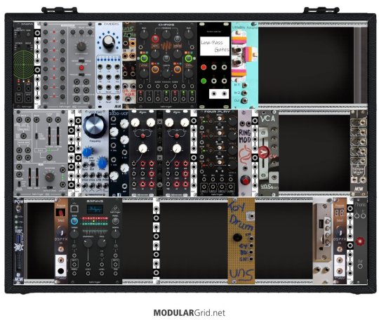
Pictured is my current modular rig* (1,2,3). In addition to these cases I currently also use a Make Noise Strega and 0-Ctrl, Moog DFAM and Spectravox, and Pittsburgh Modular Voltage Lab 2. All recordings played live, processed through Elektron Analog Heat mk1, and recorded via Zoom H4n.
Each system is housed in an Intellijel performance case. Each is intended to fill a specific purpose, and to be playable as its own instrument - though of course they're more powerful than the sum of their parts when put together.
The first is a "modular drum machine" with many voices and complex, focused sequencing. There's a couple of fun routing options and effects, but it's intended to be like a groovebox.
The second is, for lack of a better word, a texture processor. Feedback, sample mangling, and smooth tactile control are the name of the game here.
The third started off as a more classic synth, and can still fill that role with several oscillators, a filter, and a delay. But the open ended nature of so many of the modules allows for much feedback patching of CV and audio for various glitchy ends.
*The bottom row of each case is for planning purposes of changes to make, and not reflective of a secret third 3U row in the performance cases.
27 notes
·
View notes
Text


Spock’s Brain (1990) by IS Robotics (iRobot), Somerville, MA. This hard-wired analogue brain is designed to emulate the brain of an insect, modelling how the insect gait transforms seamlessly from a slow, statically stable walk to a faster dynamic running motion. It controls the gait of a simulated hexapedal robot, represented by on-board LEDs for each leg. The legs maintain synchrony with signals flowing both longitudinally and laterally. Each leg has an identical circuit; the XR-2207 is a voltage controlled oscillator for timing, the 74123 is a dual retriggerable monostable multivibrator producing a square wave output to actuate the leg, and the smaller 8 pin TL082C is a dual op-amp.
82 notes
·
View notes
Text
I started playing with a new Touch Designer video FX processing module called PixaVex developed by Eric Souther (Philosophical Tools on Patreon). I dug up some archival footage of a visit I made some time ago to an early startup robotics lab in NYC called Honeybee Robotics.
PixaVex reminds me a lot of Rutt-Etra FX, but there are great control adjustments as well as in-built oscillators for "x" & "y" control voltage signals. Overall, I think it's a very nice raster manipulation network to explore. Thanks, Eric!
For a few more samples of processing Honeybee footage, visit my Image-Maya.org art blog.
PixaVex - Visit to Robotics Lab
http://www.image-maya.org/2025/06/pixavex-visit-to-robotics-lab.html
#artists on tumblr#glitch#glitch art#video#mg#video art#image processing#markgee85#video artist#PixaVex#Touch Designer#Eric Souther#Philosophical Tools#Patreon#Honeybee Robotics#Rutt-Etra#raster manipulation#Image-Maya
3 notes
·
View notes
Text

Improvised Modular synth noise sesh with DIY module i made using Daisy_SM.
It has drums (Kick, Snare, Cymbal) , Noise drone Oscillator, clock output, Random gate output, & 2 random voltage outputs.
all being controlled by MRC Delta which is being clocked by my module
29 notes
·
View notes
Text
Finally got my Eurorack system updated on ModularGrid — I hadn't gotten around to setting up a few of my custom modules, like the Harald Bluetooth Receiver, the Toy Drum, my true diode Ring Modulator, and my analog logic module "Lola".
Starting with the top left is the Behringer Radar, a contact mic and input amplifier with a gate and a triggered envelope. It's a version of the Mutable Instruments Ears (itself an adaptation of the MTM Mikrophonie); the big change is that all the sensitivity and envelope jumpers are brought out to front panel switches.
Next is one of North Coast Synthesis's "Passive Multiples and Friends", which I built as a mult.
Next is the Behringer Model 182, a clone of the Roland Model 100-series analog sequencer. (A Christmas gift from my wife's parents!)
Next is the MidCentury Modular Dividers, which combines a binary clock divider (simultaneous ÷2 - ÷128) and an adjustable (÷2 - ÷9) divider, both based on CMOS chips. (Built from a PCB/panel set).
Next is my homebrew analog logic module Lola. It has two sections: the unary input which takes one signal and outputs its inverse and its half- and full-wave rectified versions, and the binary input which gives you the OR, AND, and XOR of two signals. (Lola is named that because it's mostly based on the Mutable Instruments module "Kinks". I left off its S&H and added the XOR.)
Next is Chaos, a clone of the MI Marbles random gate and voltage generator.
Next is a set of two low-pass gates, made from vactrols, which I built onto a buggy (malformed) version of my oscilloscope module panel.
Next is my LittleBits Adapter, which lets me plug in the magnet-based circuit building toy modules including those from the Korg collab.
On the second row, we start with the Behringer Model 150, another Roland 100 series clone; this one is noise, a S&H, a ring mod (actually a chip based four quadrant multiplier), and an LFO.
Next looks like another Passive Multiples and Friends, but this one is my Simple Cascading Fixed Amplifier, a set of four fixed amplifiers set up to do x2, x10, or x20 without modifications and up to x400 with self-patching.
The next is a Passive Multiples and Friends, this one an OR Combiner meant to combine multiple gate or trigger signals.
Next is the Kassutronics VCO 3340, an analog VCO I built from the PCB/panel set — basically the CEM3340 chip broken out plus a sine wave output (though the chip is actually the AS3340 clone).
After that is the 3320-VCF by PM Foundations, a low-pass filter with voltage-controlled cutoff and resonance, again built from PCB/panel.
Then it's my first VoxMachina Sigma function/slew generator, followed by a dual attenuverter/mixer, followed by the second Sigma — all together basically a workalike of the Make Noise Maths. The Sigma is very versatile but mostly ends up used for envelopes and LFOs. I had the pcbs and panels fabricated from VoxMachina's uploaded Gerber files.
Next is another Passive Multiple.
The next is a Behringer Four Play, four VCAs that can be used separately or mixed together. It's a functional rip-off of, I believe, Intellijel's quad VCA design.
Next is my homemade ring modulator, a proper two-transformers-and-a-diode-ring unpowered design.
After that, built into another PMaF panel, are two copies of the IamO single-JFET VCA, followed by my version of David Haillant's Simple VCA.
And last in the center row is the Modular in a Week "A Simple Mixer, Right?" (ASMR). A basic five-channel mixer with plain and inverted outputs, I got this as a kit.
In the third row, we start with MiaW's POW, which has LEDs for each power rail, a USB power jack, an external Eurorack power breakout, and a switch that currently doesn't do anything. (I'm still debating whether I should add case lighting.)
Next is a very simple reverse-avalanche oscillator with (not particularly tracking) voltage control, built from LMNC schematics.
Next is the Behringer Brains, their adaptation of the MI Plaits; it's a tremendously versatile voice that's way too tempting to leave on speech synthesis mode.
After that is another Simple Cascading Fixed Amplifier. I think this one uses inverting amplifiers and the other uses non inverting ones?
Next is the Toy Drum — I tore apart one of those electronic drum kits with the roll-up rubber pads and wired up inputs to four of the triggers, giving me a cheap but cheerful kick, snare, hat, and cymbal set.
Next is the Harald Bluetooth Receiver, the module out of a DIY Bluetooth speaker; it'll play stuff off a paired phone, or read files from a microSD card or USB stick.
Next is the DSPFX, a very cheap 100-in-1 audio effects board, which I often use to add end-of-chain reverb/delay and stereo separation. Built from MiaW design, though I had the panel fabricated.
The final PMaF is wired in passive mixer mode; it usually combines the ASMR mixer's output with the stereo output from the DSPFX, the two channels feeding the Phonic, my custom headphones output device (based on the circuit from the Befaco Out).
That's a total of 6 purchased modules, 2 kit builds, 3 PCB/panel builds, 5 PMaF panel builds, 2 fabs from Gerbers, and 13 modules of assorted more custom building, all in a homemade case. Not too shabby, I guess.
2 notes
·
View notes
Text
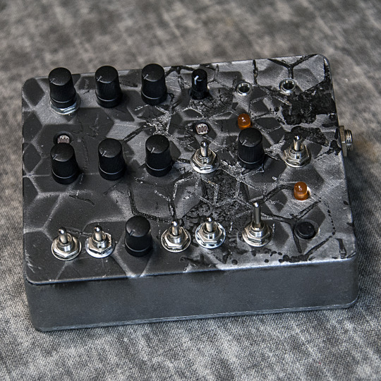
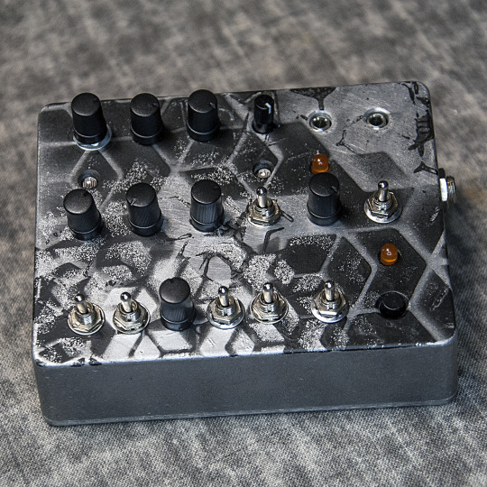
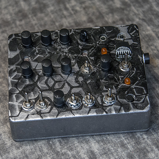
DIRTY DRONE LOWLIFE - a subbass / drone / noise texture generator
The Dirty Drone Lowlife is an experimental subbass and drone texture generator. It can be manually triggered by a TRIGGER button and externally with a TRIGGER/GATE input. The DECAY has a SHORT/LONG switch to select the range and a DECAY pot to fine tune it, from snappy to loooong. An orange LED indicates triggers and the decay (only dim with short triggers on long decay settings). With the DRONE toggle switch it can be set to play a constant drone sound as well. The sound's waveform is generated by two oscillators each with an array of possible settings: TRIANGLE/SQUARE and CLEAN/DIRTY toggle switches and of course a FREQUENCY control. Oscillator 1 has an additional OFFSET control, that can (in the range from 1.6V-2.6V) also get modulated by external control voltage via the CV input (with an orange indicator LED). Both oscillators are mixed with the BLEND control, that allows to shape the output waveform in a relatively linear manner, but the build in LDRs (Light Dependent Resistors) can also be used for that, when they are selected with the BLEND SELECT toggle switch, the user can ‘throw shade’ or ‘shine light’ on the build in sensors for a non-linear modulation of the oscillator BLEND. so it is possible to modulate the sound by hand gestures, for example. After that the signal runs through a resonant low pass filter with CUTOFF FREQUENCY, RESONANCE and SATURATION control. (please, keep in mind that in trigger mode it does not get completely quiet with no trigger.) In the end of the signal chain is a VOLUME control. Build into a die-cast aluminum enclosure painted with an unique 'burned out industry' camo pattern. Power-socket: 9V DC , 2,1mm DC jack boss-style (inside -/+ outside) PSU is NOT included. Handmade by GRM for METSÄÄN. Sold. Here’s demovideo of a previous build:
youtube
2 notes
·
View notes
Text
Electricity, Resistance, and Tunneling
What is Quantum Tunneling? The ability of elections to break barriers and this through walls?
Yes. Exactly. However; This is how electricity works. (I feel like I keep repeating myself here).
Electrons (or current) follows along a wire towards a positive charge (Voltage). And we use resistors in order to control the flow of current in a circuit.
The resistors discourage electrons from one side of a circuit to the path of least resistance. (Lol, geddit?) By disconnecting this wire "without resistance" (the quotes are because you cannot get rid of Resistance entirely) the current can go straight through the resistor.
Electrons travel *through* metal (or another conductive medium) it's simply how electronics work.
And so; when we get to tiny enough circuits, that Resistance is harder to create. And electrons go through the resistor, even when there's no power.
Which means they're also affected by latent static charge as well as the power that we want to control.
The "Wave" we keep hearing about has a bunch of different topics it covers. Light waves for one, waves created through a medium. But the one I haven't covered yet is what engineers, electricians, and mechanics would call "Phase".
"Phase" is a term used specifically for A/C(Alternating Current) and in order to generate multiple streams of power.
A basic generator has a single phase and can be recorded as a single waveform of high(positive) and low(negative) creating a back-and-forth pulling of electrons where voltage is present.
However many systems, such as aircraft, have multi-phase generators. This means that multiple different electrical waveforms are generated from a single generator.
The standard multi-phase generator is 3-phase.
And for the most sensitive electronics on the aircraft, the phase position can actually affect the operation of the equipment. As some are put specifically on certain paths with certain phases for a reason.
This harkens bank to early computer screens and oscillators used to generate images. But it'd be too complicated to go in depth here.
These phases, usually labeled A,B, and C are about 45° off from each other. Since they pull no current at the source, the generator, they don't interfere with each other.
Reference material states that it is if these phases add up to zero.
And so--what I have left to explain; Is exactly how this understanding of electric phases correlate with quantum mechanics and *states*
This will have to be done with a more coherent explanation of how current flows along voltage, and may not always flow through a path created from voltage (as above).
5 notes
·
View notes
Video
youtube
Free string synthesizer sample plugin (Strykebrett)
Strykebrett is a free sample library for Decent Sampler featuring the Hohner / Logan String Melody II with some added features. All the sounds in the video are from a single instance of the plugin with no additional plugins or effects added.
User Interface: The user interface offers precise control over every aspect of the instrument and effects. Explore parameters to refine your sound, including control over the six drawbars, envelope, amplitude modulation with LFOs, highpass and lowpass filters, velocity/dynamics, oscillator drifting, and the immersive effects of ensemble, phaser, echo and reverb.
Mixer (Bass / Treble): Unleash the power of the six drawbars to shape your tone with precision. Each drawbar controls the amplitude of a specific octave or sound, offering you unparalleled control over the instrument's harmonic richness.
ADSR Envelope: Shape your sound precisely with the Attack, Decay, Sustain, and Release parameters. Whether you desire a punchy, staccato tone or a smooth, lingering ambiance, the ADSR envelope allows you to tailor the dynamics to your liking.
Low-frequency Oscillator (LFO): The Rate and Depth knobs enable you to modulate the amplitude of four of the drawbars with the desired depth and rate. The LFOs for the treble section has a sine waveform for smooth transitions. The LFO for the bass section has a sawtooth waveform for a rhythmic effect.
Voltage Controlled Filter (VCF): Strykebrett has a highpass filter and a lowpass filter. The highpass filter ranges from 20 Hz to 2000 Hz and the lowpass filter ranges from 200 Hz to 8000 Hz.
Oscillators:
Dyn: Turns on or off the velocity controlled amplitude
Drift: When enabled, each sample will have a slight pitch drift. The pitch drift for each sample is unique and independent. It's less pitch drift in the bass samples than the treble samples.
Ensemble:
O: 3 stereo choruses with different speed and depth
Acc: Turns the ensemble off
Solo: Fast stereo vibrato
Organ: A slow stereo chorus
Effects: The phaser is the built-in phaser from Decent Sampler. The echo and reverb effects are achieved using carefully crafted impulse responses. The echo effect employs a Fulltone Tube Tape Echo recorded twice for stereo, while the reverb effect draws from a Chase Bliss Audio & Meris CXM 1978 reverb pedal with a room setting.
Echo: Select from two distinctive echo options: the short echo, delivering a classic slapback effect, and the long echo, characterized by a slower decay and numerous repeats.
Reverb: You'll also find two reverb effects: the short reverb, evoking the intimacy of a small room, and the long reverb, enveloping your sound in the vastness of a spacious environment.
#youtube#sample pack#sample library#logan string melody#hohner string melody#free samples#pianobook#decentsampler#string synthesizer#string synth#string machine#dehlimusikk#dehli musikk
4 notes
·
View notes
Text
this man has been possessed by the "dame to cosita" ghost spirit when he was possessed his body has been taken over by the "dame tu cosita" by the spirit oscillating electrical voltages in the brain wiring him to perform the infamous "dame tu cosita" dance which is entirely out of his control
2 notes
·
View notes
Text
Electronics Components and Uses:
Here is a list of common electronics components and their uses:
Resistor:
Use: Limits or controls the flow of electric current in a circuit.
Capacitor:
Use: Stores and releases electrical energy; used for filtering, timing, and coupling in circuits.
Inductor:
Use: Stores energy in a magnetic field when current flows through it; used in filters, transformers, and oscillators.
Diode:
Use: Allows current to flow in one direction only; used for rectification, signal demodulation, and protection.
Transistor:
Use: Amplifies and switches electronic signals; fundamental building block of electronic circuits.
Integrated Circuit (IC):
Use: Contains multiple electronic components (transistors, resistors, capacitors) on a single chip; used for various functions like amplification, processing, and control.
Resistor Network:
Use: A combination of resistors in a single package; used in applications where multiple resistors are needed.
Potentiometer:
Use: Variable resistor that can be adjusted to control voltage in a circuit; used for volume controls, dimmer switches, etc.
Varistor:
Use: Protects electronic circuits from excessive voltage by acting as a voltage-dependent resistor.
Light-Emitting Diode (LED):
Use: Emits light when current flows through it; used for indicator lights, displays, and lighting.
Photodiode:
Use: Converts light into an electric current; used in light sensors and communication systems.
Zener Diode:
Use: Acts as a voltage regulator by maintaining a constant voltage across its terminals.
Crystal Oscillator:
Use: Generates a stable and precise frequency; used in clocks, microcontrollers, and communication devices.
Transformer:
Use: Transfers electrical energy between two or more coils through electromagnetic induction; used for voltage regulation and power distribution.
Capacitive Touch Sensor:
Use: Detects touch or proximity by changes in capacitance; used in touchscreens and proximity sensing applications.
Voltage Regulator:
Use: Maintains a constant output voltage regardless of changes in input voltage or load; used for stable power supply.
Relay:
Use: Electromagnetic switch that controls the flow of current in a circuit; used for remote switching and automation.
Fuse:
Use: Protects electronic circuits by breaking the circuit when current exceeds a certain value; prevents damage from overcurrent.
Thermistor:
Use: Resistor whose resistance changes with temperature; used for temperature sensing and compensation.
Microcontroller/Microprocessor:
Use: Processes and controls electronic signals; the brain of many electronic devices and systems.
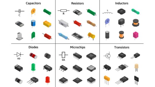
fig:google-electronics

fig:google-electronics
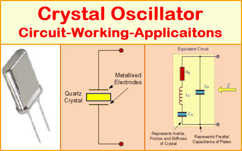
fig:Crystal-Oscillator
This list covers some of the basic electronic components, and there are many more specialized components used for specific applications within the field of electronics.
#electronic#electricity#electric vehicles#electric cars#engineering#semiconductors#wireless#cables#electronics#smartphone#hardware
4 notes
·
View notes
Text
Custom Clock Inserts
Quartz Clock Movements Open Your Vistas

Quartz clock movements are the modern-day electronic matching of conventional, mechanical control centers for timekeeping. However quartz clock movements (likewise referred to as clock electric motors) have no springs, weights, wheels, or gears to track time; instead, the quartz crystal generates a stream of pulses that are extremely fast and extremely steady, meaning that checking and subdividing the pulses provides an exact step of elapsed time. Let us see how these marvelous tools can open up a brand-new globe to you.
Non-quartz clock movements run mechanically, utilizing rotational force to turn a flywheel and a collection of equipments to determine specific time units (i.e., secs). Without regulation, the flywheel would certainly spin also quick, which is where pendulums and escapement systems can be found in. The pendulum is limited to turn one extent in half a second, and the gear network converts the oscillation right into secs, minute, and hours.
Modern electronic motors work identically-- at the very least to the onlooker-- although a completely different method is utilized to obtain the exact same outcomes. The first thing one requires to comprehend is that quartz crystals normally vibrate at their resonating regularities when a voltage decrease is related to them. Next, one must realize that the entire point of clocks is to track elapsed time (resetting every 12 or 24 hr), which whether this is done mechanically or electronically is a non-issue.
Nonetheless, the electronic strategy has lots of advantages that exceed just removing the bulk of flywheels, weights, and gears. Electronic motors in essence digitize the entire process, transforming what made use of to be performed in hardware into software program. This gives them a lot better adaptability and adaptability than their mechanical equivalents, and actually they can carry out essentially whatever functionality can be thought up due to the fact that shows has no hardware restraints.
As an example, suppose we intend to extend the resetting time, or the duration at which whatever wraps around to where it began? Twelve hours and twenty-four hours are prominent alternatives, but there's absolutely nothing preventing one from going a full week, and even a month!
Naturally, there's no factor implementing such time expansions if you couldn't reveal them, implying particularly adjusted dials and potentially an additional hand. For the once a week period, the days are printed in the center of the dial and the (short) extra hand leaps to the next day every 24 hr. In a similar way, for once-a-month durations, dates of the month are published along the dial's circumference and a lengthy hand ticks to the following once a day.
A neat option "clock" movement that you can obtain monitors tide level. The only actual distinction is going from a solar cycle to the lunar cycle, which is 24 hr and 50 mins. The motion has to be initialized and calibrated for neighborhood problems, but once this is done the tide degree will certainly always be accurate.
The tide-level motion (which can be combined with common timekeeping to display time and trend on one face), is a kind of lead-in to movements that depart from periodicity. Right here, the thing revealed is a weather phenomenon, such as moisture or temperature, and the single hand revolves between two extremes of a scale. Sensors are made use of to discover present worths, and the electric motor converts the value into hand position.
The astute viewers will certainly understand that we are no longer in the world of quartz movements, as there is no reason to track elapsed time. But the digital quartz innovation has freed up the imagination to assume in regards to software instead of hardware. clock parts
A fascinating by-product of all this is that there is a market for clocks and attributes of the past, such as grandfather clocks with oscillating pendulums. The digital movements can suit such needs via simulation, even though pendulums are no more working components; this is particularly valuable for clockmakers that want to bring back an old, non-functioning heirloom. Obviously, quartz clock movements open your panoramas.
youtube
2 notes
·
View notes