#What are RF Modules
Explore tagged Tumblr posts
Visit Tumblr Blog
Explore Tumblr blogs with no restrictions, modern design and the best experience.
Last Seen Tumblr Blogs


Fun Fact
In 2020, 27% of US Tumblr users had an annual household income of over $100,000.
Text
https://www.futureelectronics.com/p/semiconductors--Led-lighting-components--led-driver-modules-rev--constant-current-acdc-led-drivers/xi180c125v200bsf2-signify-north-america-8124576
Constant voltage circuit, residential LED Lighting, modulator circuit
100 - 277Vac, 180W, 100 - 1250mA, 70-210V, [0-10V], IP66 LED Driver
#Constant Current AC/DC LED Drivers#XI180C125V200BSF2#Signify North America#voltage circuit#residential LED Lighting#modulator#What are RF Modules#Lighting Components#Led outdoor lighting#Indoor LED Driver#LED Driver#led home lighting
1 note
·
View note
Text
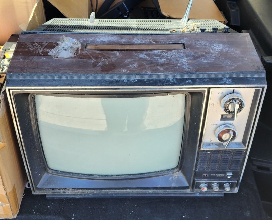
So I've picked up a 1976 Sears TV and I'm gonna clean it up and wire it up to several RF modulators so I can make my own TV channels.
I think I'm gonna have a channel that's running the old TV Guide software, and a MST3K channel, maybe a Have I Got News For You channel.
I definitely need a Star Trek (all of them) channel.
What else would you do channels for? Maybe some classic cartoons... My roommate suggested putting on some videos of commercials from the 90s.
334 notes
·
View notes
Text

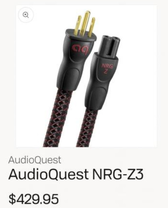
Thankfully this post was a joke. He is not going to put a power cable on a TV that costs less than the actual cable. But I had to look up the product page and see what kind of nonsense AudioQuest came up with for this one. I've already checked out their $12,000 power cable, so I'm curious how their "budget" $430 version works.
-----------------------------
Low-Distortion 3-Pole Power Cable
Perfect-Surface Copper (PSC) with Silver-Plated Drain Wires
Quiet Background and Minimal Active-Circuit Misbehavior Due to RF/ND-Tech (US Patent # 8,988,168) & Direction-Controlled Conductors and Shields
ZERO (No) Characteristic Impedance (Uncompressed Current Transfer)
THE CHALLENGE: No matter how perfect an AC power source, distortion is added within any AC cable. Even the most sophisticated filters and power supplies cannot eliminate this Transient Intermodulation Distortion (TIM) as the induced RF noise modulates the low-level audio/video signal.
THE SOLUTION: NRG-Z3 cables use direction-controlled Perfect-Surface Copper (PSC) strands in a 7-strand Semi-Solid Concentric conductor arrangement in which strands are packed more tightly and never change position within the bundle. This construction significantly reduces strand interaction distortion. The extremely pure and smooth-surface PSC conductors minimize distortion caused by grain boundaries which exist in any metal conductor.
NRG-Z3’s patented RF/ND-Tech and direction-controlled Silver-Plated shield conductors efficiently drain RF noise from the line and neutral shields to ground via the third “ground” pin. In addition. NRG-Z3’s common-mode phase-cancelling array provides additional differential linear filtering. The net result is powerful, dynamic and immersive!
--------------------
Okay, Star Trek needs to hire these people to write their technobabble. This is next level "reverse the polarity" nonsense.
Gotta get that PSC to control the TIM or else you'll be SOL trying to minimize that grain boundary distortion. The phase-cancelling array is really the star of this cable though. Whenever I hear differential linear filtering, I'm just like, "THIS IS NOT DYNAMIC AND IMMERSIVE ENOUGH!"
34 notes
·
View notes
Text
HDMI RF: The Little Prince of Signals
On Asteroid AV-612, where coaxial vines coil like sleepy serpents and screens glow like captive stars, lives a lonely modulator. Its name is HDMI RF, and its magic turns digital whispers into analog constellations—forging bonds between ancient TVs and modern worlds. Let’s wander its universe, where 4K dreams dance on CRT skies.

1. The Modulator’s Tiny Planet
HDMI RF tends its garden:
RG59 Vines: Stretches signals 500m—far enough to touch factory robots and hospital screens across cosmic dust.
Channel Flowers: Blooms 80+ frequencies, each a color for grandma’s CRT or a surgeon’s monitor.
Frostfire Heart: Works -10°C to 45°C, smiling as Siberian snowflakes melt on its circuits.
Why USB-C’s asteroid fails: “Too busy chasing wireless comets to root in copper soil.”
2. Journey to Strange Planets
🌍 Planet of the Factory Golems: “Why do sparks fly?” asked the Prince. “To light the path for welding robots,” HDMI RF replied, coaxing 4K feeds through gremlin storms.
📺 Planet of the CRT Rose: An old TV sighed: “New streams forget me.” HDMI RF touched her screen—Stranger Things bloomed in 480i petals. “What’s obsolete is just lonely.”
🏥 Planet of Healing Scry-Glass: Guarded MRI screens from Wi-Fi ghosts. “Chaos fears a steady signal,” it hummed, syncing heartbeats.

3. The Fox’s Wisdom
“Tame me,” begged a flickering screen. HDMI RF shook its head: “My magic needs no Wi-Fi. Just trust—and RG59 cables.”
4. The Businessman’s Streaming Empire
“I beam 8K through air!” boasted a satellite. HDMI RF watched a village antenna dance: “Your sky-signals fade. My copper vines? Eternal.”
5. Where Stars Still Sing
Rural Villages: Children gather ’round antennas, HDMI RF turning one Netflix stream into 48 constellations.
Retro Arcades: GoldenEye 007 glows on tube TVs, unbroken as the Prince’s promise to his rose.
Factory Floors: Robot diagnostics pulse down 500m cables—sparks bowing to the modulator’s spell.
Epilogue: The Signal’s Secret As rockets chase thinner streams, Asteroid AV-612 glows gold. For what truly connects worlds isn’t speed—it’s the magic to speak every screen’s language.
1 note
·
View note
Text
Best Partner for Wireless Modules: A Comprehensive Antenna Selection Guide
n the field of wireless communication, antenna selection is crucial. It not only affects the coverage range and transmission quality of signals but also directly relates to the overall performance of the system. Among various wireless modules, finding the right antenna can maximize their potential, ensuring stable and efficient data transmission.
When designing wireless transceiver devices for RF systems, antenna design and selection are essential components. A high-quality antenna system can ensure optimal communication distances. Typically, the size of antennas of the same type is proportional to the wavelength of the RF signal; as signal strength increases, the number of required antennas also grows.
Antennae can be categorized as internal or external based on their installation location. Internal antennas are installed within the device, while external antennas are mounted outside.
In situations where space is limited or there are multiple frequency bands, antenna design becomes more complex. External antennas are usually standard products, allowing users to simply select the required frequency band without needing additional tuning, making them convenient and easy to use.
What are the main types of antennas?
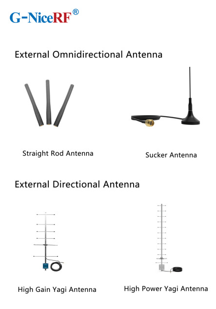
External Antennas: These antennas can be classified into omnidirectional antennas and directional antennas based on the radiation pattern.
Internal Antennas: These antennas refer to antennas that can be placed inside devices.
Omnidirectional Antennas: These antennas radiate signals uniformly in the horizontal plane, making them suitable for applications that require 360-degree coverage, such as home Wi-Fi routers and mobile devices.
Directional Antennas: These antennas have a high emission and reception strength in one or more specific directions, while the strength is minimal or zero in others. Directional antennas are primarily used to enhance signal strength and improve interference resistance.
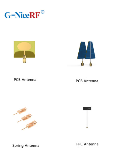
PCB Antennas: These antennas are directly printed on the circuit board and are suitable for devices with limited space, commonly used in small wireless modules and IoT devices.
FPC Antennas: FPC antennas are flexible printed circuit antennas that are lightweight, efficient, and easy to integrate.
Concealed Antennas: Designed for aesthetic purposes, concealed antennas can be hidden within devices or disguised as other objects, making them suitable for applications where appearance is important without compromising signal quality.
Antenna Selection Guide
When selecting the appropriate antenna for a communication module, it's essential to first determine whether to use an internal or external antenna based on the module's structure.
External Antennas: These antennas offer high gain, are less affected by the environment, and can save development time, but they may take up space and impact the product's aesthetics.
Internal Antennas: These have relatively high gain and are installed within the device, maintaining a clean and appealing exterior.
Sucker Antennas: These provide high gain and are easy to install and secure.
Copper Rod Sucker Antennas: Made from large-diameter pure copper radiators, these are highly efficient with a wide bandwidth.
Rubber Rod Antennas: Offer moderate gain at a low cost.
Fiberglass Antennas: Suitable for harsh environments and ideal for long-distance signal

External Directional Antennas
Typically used in environments with long communication distances, small signal coverage areas, and high target density.
Panel Antennas have high efficiency, are compact, and easy to install, while considering the impact of gain and radiation area Yagi Antennas offer very high gain, are slightly larger, and have strong directionality, making them suitable for long-distance signal transmission; however, attention must be paid to the antenna's orientation during use
Internal Antenna Selection
Most internal antennas are affected by environmental factors and may require custom design or impedance matching
Spring Antennas are cost-effective but have low gain and narrow bandwidth, often requiring tuning for good matching when installed Ceramic Patch Antennas occupy minimal space and perform well, but have a narrow bandwidth
For details, please click:https://www.nicerf.com/products/ Or click:https://nicerf.en.alibaba.com/productlist.html?spm=a2700.shop_index.88.4.1fec2b006JKUsd For consultation, please contact NiceRF (Email: [email protected]).
2 notes
·
View notes
Note
Hey Engie!
I’m going around asking everyone what they would like to get for Christmas :)
What do you want?
🎁
-@firemaniac-pyro
"Well, hey there, Pyro! Happy Holidays! Mighty thoughtful of ya to be askin'. I reckon I could use some electronic bits — RF Modules, MOSFETs, or sort. But if you're lookin' for somethin' a bit simpler.... flannel shirts. Guitar strings wouldn't go amiss neither, and I'll never turn down some good BBQ spice rubs or fresh coffee beans. "
He gave Pyro a warm smile. " How 'bout you? What's on your wish list this year?"
#( answered. ) that contract was all hat and no cattle!#firemaniac pyro#[ do you think pyro knows what these are ]
1 note
·
View note
Text
The People have spoken,
JermaTV is go. If anyone is interested/has technical questions feel free to ask but I’ll basically be modifying a composite TV RF modulator to be amplified slightly through an LNA board and out into a dummy load/highly non-efficient antenna. (I’ll play with power levels and see what the best output I can get is while following local regulations)
As far as what I’ll actually broadcast, please send me your favourite jerma moments™ and I’ll broadcast it on air / see if I could make a YouTube video out of it if you guys want.
#jerma#jerma tv#ham radio#amateur radio#amateurradio#amateur television#196#jerma985#electronics#electrical engineering
19 notes
·
View notes
Text
AM-Detection -the not easy way
Sometimes quite simple things can be a real nightmare if you take a closer look. One of those is AM detection. Your worst enemies are distortion and fading (the latter results in the first). The AM-Detector is only one little part in a receiver, exactly that kind of part usually no one thinks about. "It works, so what should be wrong with?" -a lot and sometimes there's more wrong than right.
A good part of that distinctive AM-Sound we all know is because of the Detector, even under the best conditions. If you're listen to shortwave or the broadcast band during the night then you also have to cope with Fading. Shouldn't be that problem, the automatic gain control takes care of that, right? Ehmmm... Yes. Sometimes. Why the sound gets so distorted when the signal goes down? Just because it's very often 'Selective Fading' and not just Fading -and your Detector doesn't like it.
Really good AM-Reception has a lot in common with High-End-Audio: if it shall work well EVERYTHING has to be well. So let's just talk a bit about Detectors...
Basically the Detector just splits the Audio Signal from the received and amplified Signal. Sounds easy and in fact it is -up to some degree. If you want more than this things getting complicated -really complicated. In at least 999 out of 1000 AM-Receivers for the Detector a small circuitry called 'Envelope Detector' is used, it's just a small Diode (Tube or Semiconductor), a few Resistors and small Capacitors. So, from the view of the Development Engineer: just put half a dozen cheap Components together and Bob's your Uncle. To tell the Truth: compared to the expense that thingy works surprisingly well. Because of this it's the 'Gold Standart' for this task since at least the mid 30s. But as good as it is, it absolutely has it's Limitations. Up to about 15...30% Distortion at a 100% Modulation Level is one, the inability to detect a signal with different sidebands (>selective Fading!) properly another.
To overcome these Limitations a thing named 'Synchronous Detector' was developed many Decades ago. This kind of Circuit has many advantages over the Envelope Detector, but to make one the complexity and the component count of those is just hilarious compared to the Envelope Detector. If only the result counts and nothing else: that's the way to go. We'll talking later how this exactly works, but before this you have to know that in a receiver with a Synchronous Detector also an Envelope Detector is needed: just for tuning in. So first we'll have a closer look how we can get the most ideal Envelope Detector.
Basically it's quite simple: want to have low overall Distortion? Feed it with at least 'a few' volts RF at it's input for having a high ratio between the input voltage and the 'forward voltage' of the Diode. Want low Distortion at low modulation levels? Use a Diode with low Impedance and a load Resistor with a value as low as possible. Want low Distortion at high modulation levels? Just make the input Impedance of the following Stage as high as possible for having the highest possible Ratio between the Resistance of the Load Resistor and the input Impedance of the following Stage.
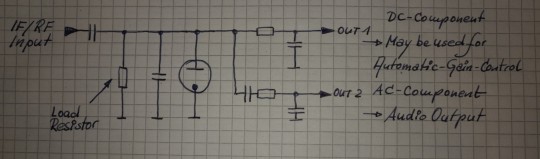
The Receiver i wanted to use (R+S EK07) has an IF output, meant for exactly such things, the IF Level there's about 250mVpp @ 300kHz. So having everything above in mind -and just adding a 700mVpp IF output for the Synchronous Detector and an additional AGC-Circuitry, then we're coming to this:

The EK07 is a fully tube equipped receiver, so i also want to use tubes as far as possible and -like in the EK07- in a way which guarantees 10k's of Service hours. If at one point a Semiconductor may perform muuuch better -ok, so then. First of all i want high performance. So what tubes may perform optimal here?
For the first IF-Amp (IF1) not much is needed, the Gain is only about 3, the output voltage low and besides that it has to be an remote-controlled type. Selectivity isn't needed or desired, so no IF-Can, only a Broad-Band setup. Nearly every IF-Tube with a Transconductance of at least about 3000mhos (3mA/V) would do that job. To have better performance i took the EF805s, which is a Special Quality Version of the EF85 -or 6BY7.
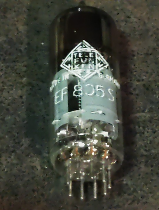
Transconductance is about twice what's needed, so we'll have Gain to spare, anyway, it's getting controlled with the AGC so it will work with less current which adds greatly to the service life. So no problems here.
For the second IF-Amp (IF2), things aren't exactly that easy. First: the output for the Synchronous Detector is placed between both Amps and has to deliver a constant voltage, so for the 2nd IF we need an Amplifier with an fixed Gain. A STABLE fixed Gain over long time periods. Further we want to have a relatively high and undistorted output voltage which calls for quite a bit of gain. Wait: there was also that thing with the low-value Load Resistor in the detector itself -so we also need a quite reasonable amount of output power from this stage. In Addition we want to have a stable gain for a time as long as possible. A IF-Tube like the EF805s could also handle this, but then we have to 'beat the crap' out of this thing. Not a good start for a long and stable service life, also not with Special Quality Tubes.
Because of all that my choice was a kinda 'special'-Special-Quality type: the E81L.

The datasheet calls this a 'Long range, Special Quality Tube for the use in Telephone Equipment'. Telephone Equipment? Like an answering machine?? Nope, by far not. Back in these days telephone companies needed to have Amplifiers for pushing the calls through loooong cables for long range service. But: this was all multiplex service, so they pushed dozens and dozens of calls simultaneously through one pair of wires or a Coax. The same way like for cable TV. THIS was these bulbs were meant for. For this task every company employed tens of thousands of such tubes 24/7/365. If a single one failed -most likely somewhere in nowhere of course- they had a problem. So they absolutely had to last.
These little bulbs are designed for about 4.5W plate dissipation at 20mA, the Transconductance is 11000mhos (11mA/V)-so it's about twice an usual IF Tube in every respect. So that's exactly what's needed here: a tube especially designed to last, quite powerful, so we can drive it with comfortable low settings, enhancing service life and stability much further.
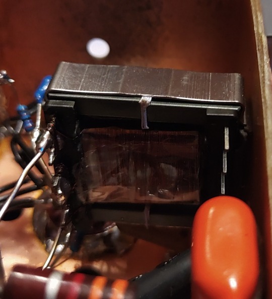
Because we need some amount of power the usual Broad-Band Amplifier arrangement (still: selectivity is not wanted or desired) with just a plate Resistor isn't good here, a suitable inductor works way better here. This has the further advantage that we can build it with a Tab like an Autotransformer -we don't need that much voltage it could deliver with that inductor by far, so this adds further to a good SNR and lower output Impedance. 300kHz trough a transformer? Yep, no problem. Just use the right core. Here it's not a laminated iron core but a ferrite one instead. Cause it's a single-A Amplifier of course we must add an air-gap, preventing saturation.
In a penthode stage the gain depends nearly exclusively on the Transconductance of the tube used, have to much just cut it down. The E81L has a quite high transconductance, about 3 times more than needed -and in the same order than big output tubes like the 6550, EL34 or 6CA7. For cutting that down to the desired level just put a Resistor or Pot in series to the bypass cap of the cathode Resistor. This acts as an series feedback so it also enhances linearity and long time stability greatly. Yap, i thought quite a while about which tube i should use here.
So after all Amplification is done now, we need a Diode for the Envelope Detector. Back in the Octal-Days this was the 6H6 / EB34, later in the Miniature-Days the 6AL5 / EAA91, both with two separate diodes in one bottle (or Can for the 6H6). These were not A DIODE, these were THE DIODE, so there's not much to choose from. Both are kinda close to each other, but are these ideal for what we want? They both can handle a reverse voltage of several hundreds of volts, so waaaay more than we need here. Both having a Plate Resistance of 600-something Ohms per System which is quite low -could be lower, even with both Systems in parallel. Of course these would be work well, no doubt about. But still.... Hey, this should be High-end so we're whining here at a very high level!
Basically we can use EVERY TUBE as a diode: just take the control grid as Anode, the Cathode as what it is and everything else as Shielding. We don't need hundreds of Volts reverse Voltage, nor high current, so also no big Cathode. We only want to have an internal Resistance as low as possible, so a close spacing between the Grid and the Cathode. This calls for a small Tube with a high Gm (or Transconductance) -like the 6AK5 / EF95. Can it handle the reverse voltage we need? Datasheet says 50V, so at least twice of what's needed. So just take one, put some current trough and take the voltage drop. Result: 210 ohms -way less than that what one of the double-diodes would provide, even with both Systems in parallel. Fits very well!

This is the soviet-military version of the 6AK5W / E95F. Special Quality. See these 'trenches' in the bulb? And the microscopic rivets holding the Plate together? The Soviets literally ruggedized the heck out of this tube! Why? Just because they used it widely in their Fighter Planes, ICBM's, Tanks and so on. Doubts about the soviet built quality? Hey, they wanted to win WWIII with them -so: nope. If you ever saw a ruggedized tube: this it is.
After the Detector itself is done, we come to last part of our little contraption: the buffer Amplifier. At the output of the Detector we have the AF as well with the overlayed AGC-Voltage and we want to have an input Impedance as high as possible for the Buffer Amp. Voltage Gain isn't needed -we have plenty of both from the Detector- so we just can use a Cathode Follower for the buffer. Ideally the Buffer should handle both voltages simultaneously, but then the output will be negative with respect to Ground. How to....? Simple: just put that thing between a positive and a negative supply rail. Then the output can swing freely between every positive or negative Potential as desired. Further: we don't need a Grid Resistor! The Grid just follows any voltage swing of the Detector, this also adds to a high input Impedance.
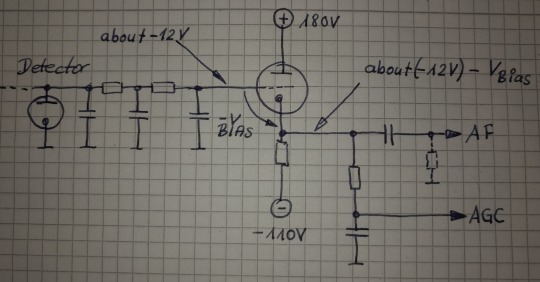
This Circuit will provide us a very high input Impedance, but this is High-End! So: what tube will be the best for? Because of the lack of any Grid Resistor the input Impedance depends now largely on the contact potential of the grid. So we want a tube with low contact potential which calls for a tube with a low Transconductance. Further we want a tube which needs only a low bias voltage for it's Grid, 'cause we'll loose any bias-volt in our AGC-Output voltage. This calls for a tube with an high Gain. Low contact potential and low Transconductance? High Gain?? That's the 12AX7 / ECC83! Ok, it's of course a double Triode, but we still can use the second system for something else -like for the Line-Output Amp. In that Stage there's not much needed so it also will perform well enough there -we're still talking about AM!
So let's put everything neatly together, adding adequate shielding and so on -and we get this:
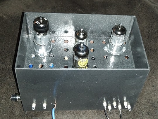
So now it's time to have a closer look we did everything right. Just put a 300kHz-Carrier in, 100% modulated with a triangle-signal. We should get a perfect Triangle at the AF-Output -if physics are with us. Due to the Triangle Signal any Distortion can easily be spotted on the Scope.
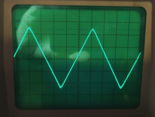
Looks promising! But somehow... Is the beam defocused? Let's take a very close look:

No, it's not. Those are just the very small remnants of the Carrier, so we actually have a look how the Detector works on a nearly 'microscopic' Level. I could take a measurement how much distortion we have left, but the Flanks of the Triangle are perfectly straight, so the Distortion will be really small -like 1% or so worst case. At least for the moment it's not worth the Effort. Compared to the usual 15...30% Distortion at a 100%-Modulation level this works really well, there's no doubt about.
So finally: we wanted to have a Envelope-Detector as good as possible and here we are. Ok, tbh it's better than needed, cause finally the REAL Detector will be a synchronous one. So why i took this that far? Easy: because of mental peace. Now i never have to think about if that part of the whole final thing could work better. As i said before: it's High-End.
Will update you if the next module is ready. But i fear this here was just the more easy part of the whole thing. From now on things may get a bit more tricky...
3 notes
·
View notes
Text
🎯 "Think no one’s watching you? Think again…" 👀📡
This pocket-sized bug detector is blowing minds on TikTok! Here’s why everyone’s grabbing one:
🔍 Detects hidden devices — even wireless cameras & transmitters 📶 Scans 40–3800MHz — covers GSM, 3G, 4G, DECT, Bluetooth, Wi-Fi & more 📊 Real-time reports + modulation ID — get smart alerts, not just beeps 🚀 Adaptive scanning — finds what others miss 👖 Fits in your pocket — spy-level tech without the spy price
👉 Tag someone who needs this — before it’s too late.
1 note
·
View note
Text
WPC Certificate for 5G Devices: What Brands Need to Know
With the rapid rollout of 5G technology in India, the demand for next-gen wireless devices—from smartphones to IoT modules—is growing at an unprecedented rate. However, before any of these devices can legally enter the Indian market, they must comply with the WPC certification process.
Whether you’re a tech brand, OEM, or importer, this blog explains everything you need to know about the WPC certificate for 5G devices, the approval process, and how it impacts your product’s entry into India.
What is WPC Certification?
WPC Certification is issued by the Wireless Planning and Coordination (WPC) Wing under the Ministry of Communications, Government of India. It ensures that any radio-frequency (RF) device complies with India’s frequency allocation regulations.
The most common approval required for wireless devices is the WPC ETA Certificate (Equipment Type Approval), which applies to products that operate in license-free frequency bands, such as:
2.4 GHz / 5 GHz (used for Bluetooth and Wi-Fi)
865–867 MHz (used in RFID, LoRa)
13.56 MHz (used in NFC)
For devices operating on licensed frequency bands, like most 5G-enabled equipment, a different set of approvals may be needed.
Do 5G Devices Need WPC Certification?
✅ Short Answer: Yes – in most cases.
While 5G uses licensed frequency bands, most 5G devices also include technologies such as:
Wi-Fi (2.4/5/6 GHz)
Bluetooth (2.4 GHz)
NFC or RFID chips
GPS (sometimes)
Because of these wireless components, WPC ETA certification becomes mandatory—even if the 5G radio itself operates under licensed conditions.
So, any 5G smartphone, tablet, router, or IoT device that includes Bluetooth or Wi-Fi functionality must obtain a WPC ETA certificate before it can be imported, manufactured, or sold in India.
Examples of 5G Devices That Require WPC ETA
Here’s a list of common 5G-enabled products that require WPC ETA approval in India:
5G smartphones and tablets
5G Wi-Fi routers and CPE (Customer Premises Equipment)
Smart 5G wearables (e.g., watches, bands)
Industrial 5G IoT modules with Bluetooth/Wi-Fi
5G-enabled laptops or AR/VR devices
5G drones with telemetry radio modules
If any of these devices include unlicensed band communication, they fall under the WPC ETA requirement.
Documents Required for WPC ETA Certificate
To obtain the WPC certificate in India, you need the following documents:
RF Test Report – from an accredited lab (NABL or foreign-recognized)
Product Datasheet – including RF specifications
User Manual
Authorization Letter – if using a consultant
Company Documents – PAN, GST, Importer Exporter Code (IEC)
Online Application – via the Saral Sanchar portal
Pro Tip: If you’re unsure about the process, working with a WPC consultant can save time and help avoid application rejections
What if the RF Module is Pre-Certified?
If your 5G product uses a pre-certified RF module (e.g., Wi-Fi/Bluetooth chip), you may not need a new ETA—provided:
The module has already been granted WPC ETA
There’s no modification to the hardware
You provide proof of certification during customs clearance
However, for most consumer electronics, brands still apply for device-level ETA to avoid disputes and delays at customs.
Why WPC Certification is Critical for Importers
Customs authorities check the WPC certificate before clearing RF-enabled shipments. Without valid documentation:
Your devices may be held or confiscated
You could face penalties and fines
Your IEC license may be blacklisted
Product launch timelines can be delayed
Getting your WPC ETA license in advance ensures smooth import clearance and eliminates legal risks.
WPC ETA Certificate: Timeline and Validity
Processing Time: 2–4 weeks
Validity: Lifetime (unless RF module is modified)
Renewal: Not required
The WPC license is device-specific and linked to its RF specifications. If your product changes in terms of frequency, output power, or antenna design, a new ETA must be obtained.
Role of a WPC Consultant for 5G Devices
Applying for a WPC ETA certificate can be complex—especially for 5G products with multiple wireless functions. A professional WPC consultant helps by:
Identifying the right frequency bands involved
Coordinating with test labs
Managing the Saral Sanchar portal application
Ensuring timely documentation and approval
Brands working with a WPC ETA consultant reduce the chances of application rejections and speed up time-to-market.
Common Mistakes Brands Make
Ignoring WPC certification due to focus on 5G licensing
Assuming licensed 5G operation exempts ETA
Using non-certified Wi-Fi/Bluetooth chips
Not checking customs requirements before import
Applying late and missing product launch deadlines
Avoid these pitfalls by starting the ETA process early and consulting experts when needed.
Final Thoughts
In the era of 5G transformation, the importance of WPC certification cannot be overstated. Most 5G-enabled devices still rely on Wi-Fi, Bluetooth, and NFC technologies, which fall under India’s license-free RF bands—making WPC ETA certification mandatory.
Whether you're launching a 5G smartphone or a connected IoT device, ensure you have your WPC certificate in India ready before import or sale. Work with a trusted WPC consultant to simplify the approval process, minimize delays, and get your product to market faster.
0 notes
Text
[IOTE2025 Shenzhen Exhibitor] SHANGHAI RSID SOLUTIONS will be exhibited at IOTE International Internet of Things Exhibition
With the rapid development of artificial intelligence (AI) and Internet of Things (IoT) technologies, the integration of the two is becoming increasingly close, which is profoundly affecting the technological innovation of all walks of life. AGIC + IOTE 2025 will present an unprecedented AI and IoT professional exhibition event, with the exhibition scale expanded to 80,000 square meters, focusing on the cutting-edge progress and practical applications of "AI+IoT" technology, and in-depth discussion of how these technologies will reshape our future world. It is expected that more than 1,000 industry pioneers will participate to exhibit their innovative achievements in smart city construction, Industry 4.0, smart home life, smart logistics systems, smart devices and digital ecological solutions.
SHANGHAI RSID SOLUTIONS CO., LTD will participate in this exhibition. Let us learn about what wonderful displays they will bring to the exhibition.
Exhibitor Introduction

SHANGHAI RSID SOLUTIONS CO., LTD
Booth number: 9B31-2
August 27-29, 2025
Shenzhen World Convention and Exhibition Center (Bao'an New Hall)
Company Profile
Shanghai RSID SOLUTIONS Co., Ltd., headquartered in Shanghai, is a professional one-stop equipment supplier specializing in card manufacturing and application solutions. The company is dedicated to providing complete solutions for smart card and RFID production, personalization, and more. With more than 20 years of industry experience and the trust of many users, our company aims to become the most professional international supplier in China. Through our global network, we offer tailored pre-sales and after-sales services to meet diverse customer needs. Whether you are a card manufacturer, personalization center, or card issuer, we provide reliable services and abundant resources to support your business.
Product Recommendation
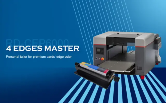
4 edges master is engineered exclusively for high-efficiency, vibrant color edge printing on cards consumping low. Fearturing 4 removable card jigs, each with a 400-card capacity, it can achieve automatically four edges printing in a single pass, reaching speeds to 4000 UPH. Adapting CMYKW printing creates colorful and up to 1440 dpi images, beyond traditional colored core laminating process. It’s also a cost-effective alternative gold/silver stamping to stimulate gold/silver color. What’s more, its material versatility extends to metal, glass, wood, and silicone surfaces. New templates can be inverted within seconds for quick job changes. Environmentally friendly UV inks ensure toxin-free, virtually odorless printing. The printer obtains sufficient certifications including CE, FCC, RoHS, REACH, and HC for guaranteed compliance and safety.
Efficient & Precise:
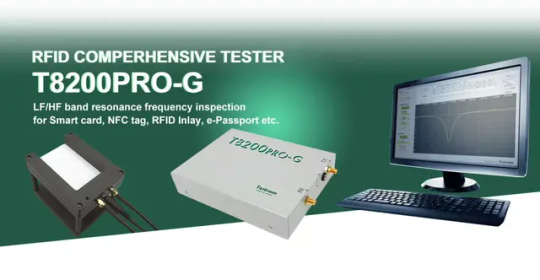
Automatically saves test results and waveforms with pass/fail judgment. Short test time (typically 0.5s).
Flexible Operation:
Supports three control modes: Manual, Digital I/O (DIO), and external software control (via Windows registry).
Multi-format Output:
Generates log files (TXT), waveform images (JPEG), and data files (CSV) for analysis and archiving.
Portable & Reliable:
USB bus-powered with compact dimensions (125×165×40mm). Ideal for lab and field applications.

PT300 : Next-Gen Industrial-Grade Reader/Writer, Supporting parallel testing for high efficiency.
Comprehensive Product Line:
Covers contact/contactless/dual interface reading/writing & electrical testing. Compatible with smart cards, modules, semiconductor chips, and products.
Exceptional Performance:
Contact interface: 1.2~5.5V wide voltage range | 2A high-current output
Contactless interface: 5~25dBm adjustable RF power | parameter testing (capacitance/Q-value)
Modular Flexibility:
Modular design for chassis compatibility and seamless expansion.
Protocol Compatibility:
Supports ISO7816, ISO14443, I2C, SPI, and Class D high-end requirements.
Applicable scenarios:
Industrial manufacturing, laboratory testing and R&D fields. It is on par with international brand readers in terms of high speed, high precision and high compatibility.
At present, industry trends are changing rapidly, and it is crucial to seize opportunities and seek cooperation. Here, we sincerely invite you to participate in the IOTE 2025, the 24th International Internet of Things Exhibition, Shenzhen Station, held at the Shenzhen World Convention and Exhibition Center (Bao'an New Hall) from August 27 to 29, 2025. At that time, you are welcome to discuss the cutting-edge trends and development directions of the industry with us, explore cooperation opportunities, and look forward to your visit!
0 notes
Text
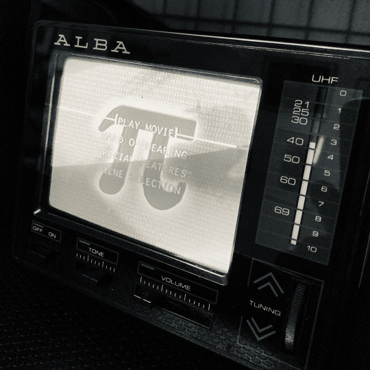
🔧⟁ PI ON THE ALBA ⟁🔧 “Play Movie” — but only after decoding the signal chain of the gods.
This is the Alba PTV-12. No composite input, no SCART. Just a single EXT ANT jack. Originally written off as a glorified noise generator—good for fuzz and flicker, but not much else.
Then came the workaround:
VHS as RF modulator → RF OUT → coax to 3.5mm adapter → EXT ANT → tuning dance → signal found.
A chain of translation. DVD signal rerouted through 90s tape logic to whisper into the Alba’s ear. A modern format repackaged as something it could understand.
Watching Pi on this tiny CRT feels more than poetic. A film about obsession, feedback, and pattern recognition—now decoded through a web of adapters and guesswork.
This is what it’s like navigating sound, communication, or even thought when you’re deaf or have APD: Nothing plugs straight in. You make the connections no one else sees. You modulate the world to your frequency.
#processzine#theinterpreter#ptv12#crtlove#pi#darrenaronofsky#vhsmodulator#apdtech#deafprocess#signalnoise#translationlayer#oldtechnewsignal#modulateanddecode#analogueadaptation#liminalhardware
0 notes
Text
Enhancing Motion Control with Rotary Torque Sensors – A Star EMBSYS Perspective
In modern engineering and industrial systems, precision and control are not just desirable—they're essential. One critical component that enables this level of performance in rotating machinery is the rotary torque sensor. Whether in automotive testing, robotics, or industrial automation, rotary torque sensors provide vital data on torque transmission, enabling more accurate control and diagnostics. At the forefront of sensor integration and embedded technology is Star EMBSYS, a company committed to delivering intelligent, sensor-driven solutions.
What is a Rotary Torque Sensor?
A rotary torque sensor measures the torque—i.e., the twisting force—applied to a rotating shaft. It is typically mounted between the drive and load components of a rotating system. Unlike static torque sensors, rotary versions are designed to operate while the shaft is spinning, making them ideal for real-time monitoring of dynamic torque in motors, gearboxes, and engine systems.
These sensors work using strain gauges, magnetic, or optical technologies to detect minute twists in the shaft and convert them into electrical signals. The data captured helps engineers assess system efficiency, monitor wear, and optimize performance in real time.
Key Applications of Rotary Torque Sensors
Rotary torque sensors are used in a broad range of industries:
Automotive Testing: To evaluate engine and drivetrain efficiency under load.
Electric Motors and Drives: For monitoring torque in high-speed, high-performance motors.
Robotics and Automation: To provide feedback for force control and safety systems.
Aerospace and Defense: In actuators and propulsion systems for performance validation.
Industrial Machinery: To detect overloads, torque variations, and inefficiencies.
Star EMBSYS – Custom Solutions for Torque Measurement
At Star EMBSYS, rotary torque sensor solutions go beyond simple data collection. The company offers customized embedded systems that not only read torque sensor data but also process, transmit, and log it for actionable insights. Whether you're designing a new system or retrofitting existing machinery, Star EMBSYS provides the tools and expertise to integrate torque measurement seamlessly.
Key capabilities include:
Sensor Signal Conditioning: Custom-designed electronics to amplify and filter sensor outputs for accuracy.
Wireless Data Transmission: Bluetooth, Wi-Fi, or proprietary RF modules to transmit torque data in real-time.
Embedded Processing: Microcontroller-based systems for onboard analytics, control feedback, and safety logic.
Custom Displays and Interfaces: User-friendly interfaces to view and interpret torque readings instantly.
Why Choose Star EMBSYS?
Star EMBSYS stands out in the industry due to its:
Deep Sensor Knowledge: From torque sensors to load cells and beyond, the team understands the science behind each signal.
End-to-End Integration: From hardware to firmware and software, Star EMBSYS handles every layer of product development.
Industry Experience: Serving clients in automotive, aerospace, medical devices, and industrial automation.
Conclusion
Rotary torque sensors are indispensable in today’s motion control and diagnostics landscape. They provide crucial insights into mechanical systems, enabling engineers to design smarter, safer, and more efficient machines. With Star EMBSYS as your development partner, you can harness the full power of torque sensing—integrated with cutting-edge embedded technology tailored to your unique application.
Visit:- https://www.starembsys.com/rotary-torque-sensor.html
#torque sensor#rotary torque sensor#servo#spring testing machine#torque wrench calibration machine#load cell
0 notes
Text
HDMI Modulators in Modern AV Distribution: Beyond Residential Use
If we consider HDMI when we think of HDMI, we usually imagine the simple cable connecting the television to Blu-ray players. But what happens if you want to disperse HDMI content across longer distances and across multiple screens or even across whole industrial or commercial premises? This is where the HDMI modulator, one device that's changing not just home settings, but also altering the way that large-scale video distribution functions in hospitality, businesses and broadcasting systems.
While a lot of resources explain the basics of what HDMI modulators do, very few discuss their practical effects and the evolving use cases for professional environments. This article explores the way these devices extend beyond the consumer market and are now essential components of the AV systems of today.

1. The Quiet Workhorse of Commercial AV Systems
In airports, hospitals, casinos as well as Corporate campuses HDMI modulators play a vital, but insignificant role. They allow for a one HDMI sources (e.g. camera, media player or the signage device) to encode and transmitted via coaxial cable, seamlessly connecting to the existing infrastructure.
This method eliminates the necessity of costly wiring rewiring and HDMI over IP configurations which is particularly important in old buildings. The ability to stream complete HD content to many (or or even hundreds) of screens with the least latency is the reason that makes HDMI modulators extremely useful for commercial applications.

2. Replacing Outdated AV Matrix Switches
The traditional AV multi-channel switchers have for a long time been the foundation of distribution of video -- however, they have restrictions. Physical ports, control systems that are proprietary and expensive scaling equipment could add cost and complexity.
Modern HDMI modulators provide an alternative to convert HDMI into RF, which allows distribution via coax, which is cheaper and adaptable. In places like multiple-room stores for retail, this method permits administrators to:
Stream multiple sources via channels-based RF
Utilize standard TV tuners to encode signals
You can easily reassign or create screens without any specialized training
Some companies have even integrated an RF-based HDMI modulation with traditional CCTV systems to provide central management.
To understand better the workings of these systems and how they can be used in various environments, look through this in-depth description of HDMI modulator functions and cases that have been written by experts from the industry.
3. The Role of Modulators in Broadcast and Live Event Scenarios
While streaming has influenced the way people consume content, HDMI modulators still play an essential part for live production as well as internal broadcasting that is low-latency. The most common uses are:
In-house broadcasting of sports venues (e.g. live feeds for concession stands as well as VIP areas)
Live auctions where speedy signal transmission is crucial.
Temporary configurations for product launches and mobile command centers
These environments need high reliability and minimal interference that HDMI modulators can provide if properly configured on RF channels.

4. Integration With Hybrid Digital Environments
A growing trend is to combine HDMI modulation and digital signage with content management systems (CMS). For instance, a store could display promo videos via HDMI modulated signals, and simultaneously displaying live-time dynamic content using CMS systems on similar screens.
It bridges the gap in traditional broadcasting and digital displays that are network-drivenwhich makes HDMI modulators a bridge technology within the evolving networks for AV.
5. What the Future Holds: 4K, IPTV, and Beyond
Modern models are now able to allow 4K encoding and some even combine HDMI modulation along with IP streaming capabilities, which allows content to stream over coax as well as across LANs at the same time. This feature is a hybrid that provides security for investment as companies transition from coax-based environments into IP-based infrastructures.
In addition, due to the growing demand for AV-over IP and intelligent control HDMI moderators have been integrated with larger automation ecosystems that work with control systems like Control4, Crestron, or KNX.

Conclusion
HDMI modulators might have started as tools of convenience for homeowners who wanted to transmit the signal from a cable box to an additional room. However, today they've evolved to become robust, flexible, and critical solutions for business distribution of audio. Their ability to integrate the old and the new is what makes them indispensable in a variety of technological settings, especially when cost, latency, or compatibility is an issue.
For up-to-date information on modern audiovisual components, connectors and integration strategies, look more information on Blikai's official site on which experts in AV and engineering can locate trusted parts and information on industry trends.
#hdmi modulator#rf video distribution#commercial AV solutions#coaxial signal encoding#live event AV#digital signage integration#AV over IP transition#modulators for business use#AV matrix replacement
0 notes
Text
Everything You Need to Know About WPC ETA Approval in India
In the rapidly advancing world of wireless technology, compliance with national regulations is more important than ever. In India, any product that operates on de-licensed frequency bands such as Wi-Fi or Bluetooth must undergo a mandatory certification called WPC ETA Approval. Whether you’re importing, manufacturing, or selling wireless-enabled equipment in India, obtaining WPC ETA Approval is a legal requirement.
This blog will guide you through the essentials of the WPC ETA Approval process, the types of products that need it, the documents required, and how expert consultants like Induce India can help you navigate the process efficiently.
What is WPC ETA Approval?
WPC stands for Wireless Planning & Coordination, which is a wing under the Ministry of Communications in India. ETA stands for Equipment Type Approval. Together, WPC ETA Approval refers to the certification granted to wireless and RF-enabled products that use license-exempt frequency bands in India.
This approval ensures that such products do not interfere with licensed radio frequencies and comply with Indian frequency allocation guidelines. It is required for most consumer and industrial electronics that use technologies like Wi-Fi, Bluetooth, Zigbee, RFID, LoRa, and other short-range radio systems.
Why is WPC ETA Approval Important?
WPC ETA Approval is a crucial step for any business looking to introduce wireless products into the Indian market. Here’s why it matters:
Legal Requirement: It is mandatory under Indian law. Selling or importing a device without WPC ETA Approval can lead to penalties, confiscation of goods, or customs clearance delays.
Spectrum Regulation: Ensures non-interference with India’s regulated frequency bands.
Market Access: Without WPC ETA Approval, products cannot be legally sold, marketed, or distributed in India.
Import Permission: This approval is a prerequisite for obtaining an import license for wireless devices.
Products That Require WPC ETA Approval
Any device that emits radio frequency and operates in a de-licensed band needs WPC ETA Approval. Common examples include:
Wi-Fi routers and modules
Bluetooth headsets, speakers, and smartwatches
RFID and NFC devices
Wireless printers, keyboards, and mice
Zigbee and LoRa modules
IoT devices and smart home products
Wireless microphones and cameras
Drones (within specific frequency limits)
If a product has an embedded wireless module, the module itself must be approved. If the module is already approved, the end product may be exempt from separate certification, depending on the integration.
Step-by-Step Process for WPC ETA Approval
The WPC ETA Approval process involves a combination of product testing and regulatory submissions. Here’s how it typically works:
Step 1: Product Testing
The wireless component of the device must be tested for compliance with Indian radio frequency standards. This testing is usually conducted by an NABL-accredited lab in India or a lab accredited by an international body such as ILAC.
The test confirms whether the device operates within the de-licensed frequency bands and complies with the allowed power output and bandwidth limits.
Step 2: Documentation Preparation
The following documents are typically required for the WPC ETA Approval process:
RF Test Report from an accredited lab
Product technical specifications
Product datasheet or user manual
Authorization letter (if applying through a consultant)
Import Export Code (IEC) for importers
Company GST and PAN details
All documents must be accurate, up-to-date, and consistent with the product being certified.
Step 3: Online Application via Saral Sanchar
WPC has digitized the certification process through the Saral Sanchar portal. Applicants must create an account, upload the required documents, and submit the application for approval. A government processing fee is also payable during this stage.
Step 4: Application Review by WPC
Once submitted, the application is reviewed by WPC officials. They may ask for clarifications or additional documentation. If the product meets all technical and legal requirements, WPC will issue the ETA certificate.
Step 5: ETA Certificate Issuance
After successful review, WPC issues the Equipment Type Approval certificate. This document certifies that the device can be legally imported, sold, or used in India without needing a separate wireless operating license.
How Long Does It Take?
The typical processing time for WPC ETA Approval is 2 to 4 weeks, depending on the completeness of the application and whether the RF test report is accepted without issue. Delays often occur due to missing or incorrect documents, so it’s important to ensure everything is accurate from the start.
Is WPC ETA Approval a One-Time Requirement?
Yes, WPC ETA Approval is generally granted for the lifetime of the product model, as long as there are no changes in the radio frequency parameters. If the product undergoes redesign or changes in RF behavior, a new ETA approval may be required.
Challenges in Getting WPC ETA Approval
Although the process is straightforward in theory, applicants often face the following challenges:
Confusion about which frequency bands are allowed in India
Choosing the right test lab for RF testing
Misinterpretation of WPC guidelines
Document preparation errors
Delay in application due to technical queries from WPC
Because of these hurdles, many manufacturers and importers choose to work with regulatory consultants to speed up and simplify the process.
How Induce India Can Help
Induce India is a trusted name in the field of product compliance and certification in India. With extensive experience in handling wireless device approvals, Induce India offers end-to-end support for obtaining WPC ETA Approval.
Here’s how Induce India adds value:
Expert guidance on applicable frequency bands and product eligibility
Coordination with accredited labs for RF testing
Documentation preparation and application filing
Handling clarifications and communications with WPC
Post-approval support for import licensing and distribution
For businesses looking to avoid costly mistakes and accelerate their market entry, Induce India provides the expertise and operational support needed to get WPC ETA Approval without delays.
Final Thoughts
In a market driven by smart devices and wireless connectivity, obtaining WPC ETA Approval is more than just a regulatory requirement—it’s a business necessity. Whether you are a startup launching your first product or a global brand entering India, understanding and complying with WPC regulations is vital.
By following the correct process, working with accredited labs, and preparing accurate documentation, manufacturers can secure approval smoothly. And with experienced consultants like Induce India, the entire process becomes faster, simpler, and far more efficient.
If you're planning to launch a wireless product in India, don't leave compliance to chance. Start your WPC ETA Approval process today and set the foundation for success in one of the world's largest and fastest-growing technology markets.
0 notes
Text
So my tv setup is janky as fuck. I have what i call "the pokin stick" so i can tap at the rf modulator when it misbehaves, which usually consists of whatever I'm trying to display fading into static. The aforementioned "pokin stick" is a broken umbrella. Here's a video of the pokin stick in action.
The reason i have this is so i don't have to climb over the stack of gamecube games, risking knocking them over. Anyway, it seems that every time i stand up to poke it, it starts magically behaving.
Always remember that fear will keep your electronics in line. Percussive maintenance is surprisingly effective.
#jibber jabbering#irl shit#don't be mean to the rf modulator it went through two hurricanes while sitting outside it's doing its best#crt tv#crt#ignore my lack of tv stand#it's 2 sewing machine cases and a bin stacked#i swear i don't live in a squatter house
1 note
·
View note