#along with my arduino kit
Explore tagged Tumblr posts
Visit Tumblr Blog
Explore Tumblr blogs with no restrictions, modern design and the best experience.
Last Seen Tumblr Blogs


Fun Fact
Tumblr has 16.74 million mobile monthly users in the US.
Text
why does retail therapy give me instant dopamine?
#i bought a skincare organizer and now i am a changed human being#my 2024 wall calenday (paintings of vangogh edition) arrives tomorrow and it's so pretty!!#along with my arduino kit
3 notes
·
View notes
Text
Prompt #004
“You move into an apartment where each room holds a different version of you.”
Standing in front of the apartment door, I hesitate. I’m not sure what I’ll find on the other side.
People have described it as a sort of pleasantly haunted house: like a wholesome version of A Christmas Carol. But knowing myself, it’s just as likely to play out like something directed by M. Night Shyamalan.
I muster up the courage, turn the key, and step into the hallway. I check, I'm alone. I double-check. Still alone.
I release a breath I didn’t realise I’d been holding.
The hallway looks like it was lifted straight from one of my Pinterest boards. Whoever designed this potential nightmare at least did it with a wabi-sabi twist. I should probably read into that and decipher the metaphor being presented, but instead I’m already moving towards one of the three doors branching off the hall.
I open the first.
Grainy light filters through the cracked door. I peek in, but my eyes take a moment to adjust. I blink more times than I care to admit before realising the entire room is in black and white.
Not metaphorically. Literally devoid of colour, like one of those old MGM films I used to watch on rainy Sunday afternoons.
Then I spot myself, swaying in the middle of what I now recognise as a 1950s kitchen. Humming along to Lil’ Darlin’ by Count Basie.
This version of me doesn’t look much older or younger, just more… domestic.
I recognise her, though. She’s the part of me that feels most grounded while harvesting tomatoes or shelling peas. She has a playlist called A Sunday Kind of Love, filled with jazz standards. She quietly dreams of slow dancing in this very kitchen. Or being held while reading by the fire.
A softer, less guarded version of me.
I realise I’ve gotten a bit emotional watching her. Something deep in my chest stirs, a quiet ache for a simpler, slower life. So I leave her be, undisturbed. Let her sway to the last notes of the trumpets, submerged in her own world.
Back in the hallway, I approach the next door, this time with a bit more confidence.
I open it to find the living room of my first apartment, dimly lit by the flickering cold light of the television. On the rug, cross-legged, sits a younger version of me. Xbox controller in hand. Focused. Determined to sneak Ezio Auditore into a Templar base undetected. Shouting something at the screen about the camera angles changing mid-jump.
Cables, resistors, and Arduino kits are strewn across the coffee table. On the sofa, a laptop is rendering some chaotic After Effects experiment, its fans at full throttle, audibly threatening to achieve flight. Next to it: a camera bag with more lenses than I will ever learn to use.
I sit beside her. I must be around twenty-four here.
She’s anxiously chewing her bottom lip, head bobbing along to Kerry King’s riffs. A lot of nervous energy in that little body.
She’s the polar opposite of the woman in the kitchen. Hard to believe they’re the same person. But they are. They’ve lived through the same trauma. They just cope differently.
One suppresses, seeks out stimulation. The other, guided by self-knowledge, knows when to slow down.
I simultaneously pity and admire her. She has a long, tiring road ahead. Soon she’ll be confronting her own demons and unlearning her own toxicity. But she’s strong. Stronger than she knows. She’ll fight battles most people wouldn’t even notice exist.
I wish I could reassure her. Maybe warn her not to date that one guy with the fear of both commitment and abandonment. But that, too, will become a valuable lesson.
So I leave her. She mumbles “Requiescat in pace” to the screen. I mentally whisper the same to her.
Back in the hallway, I reach for the last door. I try the handle. It sticks, blocked by clutter on the floor.
I put my shoulder to it, push. It resists, then gives.
I’m met by my teenage self, sitting in her bedroom. In front of a mirror. Dressed in an oversized Kurt Cobain shirt. A shoebox in her lap, full of dried rose petals, handwritten letters, poems. The breakup box.
She’s crying. Loudly. Messily. A CD clicks into the stereo. The first notes of Górecki by Lamb begin to play.
I immediately close the door.
Hard no.
I’m not sadistic enough to watch myself musically self-flagellate like that.
There are some ghosts I’m not ready to exorcise.
So I turn back toward the first door in search of tea and, maybe for a little while, the company of that simpler version of me.
0 notes
Text
213729 Fine Arts Research & Development: Honors ⋆ WEEK 2
Scanning through my ideas sheet, my most confident ideas were:
A series of larger-than-life cardboard figures in 'conversation' with one another. Speakers, mounted inside their heads would projecting fragments of field-recorded speech at each other, giving the illusion of a chattering crowd. Their voices would have been recorded from a public space with a field microphone, with any segments of conversation being spoken again through a means far removed.
Taping a sampler to my forehead and restricting any conversation made to-or-by me to being processed through a sampler. The idea being that my speech would be picked up by the sampler, chopped, and spat back out in rearranged fragments, or likewise, a person talking to me could have their voice recorded in turn, and I'd walk around with their garbled speech emanating from my forehead.

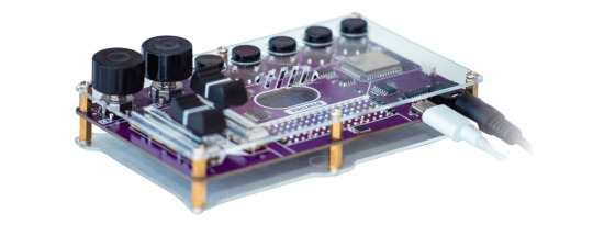
At first, I was pretty set on trying out the 'forehead sampler' idea, as I'd been wanting to get a PO-33 sampler for a hot minute, and this was as good a reason as any to fork over the $200 for one.

Why a PO-33 though? Four reasons.
It was portable, being lightweight and battery powered.
It had a built in microphone.
It also had a built in speaker.
It had 'chop' functionality, where a recorded audio would be divided amongst the buttons.
But then again, this was a very specific performance that I wanted this sampler for - and how much of this art is my own if so much of it relies on what's offered by this consumer product?
Furthermore, while simple for a sampler, I'd more than likely have to guide the audience as to how to record and playback samples with this thing. Unless I created a simplified case using 3D printing - a whole different beast mind you - I'd need something simpler.
The next step was to find other samplers that fit this parameter, along with being light enough to tape to my forehead. There was only one that got close: The Circutmess Synthia, which is a DIY sampler aimed at kids, but sends you an assembly kit.
The lack of a chop functionality turned me off, however.
My desire at this point to do a sampling performance piece was dwindling, so I got a better idea - what if I combined my two ideas, and made a sampling sculpture?

Instead of having multiple sculptures automatically conversing, I could have a single sculpture automatically sampling! The audience would still interact with a sampler, speaking into a microphone, with the sculpture speaking back in the way of a mounted speaker.
This would also allow me to fit a larger sound setup within the sculpture, freeing me to use more gear.
I brought the remnants of my 2023 cardboard sculpture, the BRAZEN FUCK OBJECT (and children) into my space for some upcycling.

So what gear would I want? I knew that music software Ableton had some live sampling setups, but I could also have a larger sampler built into the front of the sculpture like a control panel.
The audience would be remixing their own speech with this setup however, and I struggled to find any profundity in the message. If the sampler were hooked up to some kind of sequencer, and any recordings were immediately picked up and spat back out in random segments, it'd breathe a life into the sculpture.
The only problem is that hardware samplers typically don't automatically sample, slice and sequence your recordings without a human touch. I was now getting into a whole new realm of sampling entirely - I had to make my own.
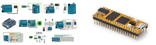
Around this time, Em introduced me to some music students from their CPRM class that were building their own synthesizer. They had been using this chip called a Daisy Seed, running a coding system called Arduino, but this coding setup could also work with a sampler.
Coding AND electronics? I was a long way from my comfort zone, so I looked up some references that I could draw from. This one was getting close to my idea, so I could possibly try borrowing from his schematics.
youtube
Frustratingly, despite noting his project being non-commercial, this guy refuses to share his code or schematics. I had to comb through multiple of his video descriptions to even hear mention of the chips he used, these being the Arduino Mega 2560, the ESP32, and most useful: the ISD1820.

Even with the boundless tutorials online for DIY samplers, along with there being music facilities for soldering, my confidence was through the floor. Where could I even begin?
I reached out to Mike for a chat.


Here's some group notes I took in my CPRM class, where I displayed the audio artwork Mycenae Alpha by Iannis Xenakis.

For our Monday class, Eugene hosted our rōpu workshop with a selection of prompts from all the other classes, allowing us to pick and choose.
I chose to collage, as we'd been instructed on printing some material beforehand.
This would be five artworks related to our study:

Along with five non-artworks:

From these, I made three collages determined by a repeated shape:


Two collages "determined by an analogous (...) palette:


And three collages determined by the juxtaposition of narrative elements:


This was a great opportunity to start whittling down all the accumulated sources I'd listed over the holidays, so I reckon I should go a little in-depth about each one and what it represents to my study.
Soundwaves form shapes, but what happens when shape forms sound?
youtube
Mycènes Alpha by Iannis Xenakis is an electroacoustic scan artwork from 1978, running for 9 minutes and 36 seconds.
Utilizing the UPIC (Unité Polyagogique Informatique du CEMAMu), a graphical composition tool developed in 1977 by Xenakis himself, sketches would made upon the specialized tablet using an electromagnetic pen, and read along an X and Y axis, being converted into musical notation as the scan passed from left to right. Mycènes Alpha was Xenakis' first demonstration of UPIC, made up from 10 sheets, which were previously planned out in sketches.
DiNunzio, Alex. ‘UPIC’. Musica Informatica, 25 Aug. 2014, https://www.musicainformatica.it/argomenti/upic.

As the story goes, when Angelo Badalamenti wrote Laura Palmer's Theme for David Lynch's Twin Peaks in 1989, he recorded it all with a single take in 20 minutes, being guided by an eerie description provided by Lynch. Music supervisor Dean Hurley was studying the MIDI notation afterwards, to which he noticed:
“The MIDI notation of ‘Laura Palmer’s Theme,’ you look at it and you’re like, ‘What’s this a picture of?’” Hurley says. “You look at it and it’s actually … Twin Peaks. Fucking eerie.”
“I showed David the photo and I was like, ‘What does this look like to you?’ and he said, ‘Yeah, twin peaks. What about it?’” Hurley says. “And I told him what it was, and he just started shouting, ‘It’s cosmic! It’s cosmic! It’s cosmic!’
Mejia, Paula. ‘This Previously Untold Twin Peaks Story Is Perfectly Eerie’. Vulture, May 2017, https://www.vulture.com/2017/05/twin-peaks-secrets.html.

On the same waveform (ha!) to this, would be the spectrogram for Aphex Twin's ΔMi−1 = −∂Σn=1NDi[n][Σj∈C{i}Fji[n − 1] + Fexti[[n−1]], otherwise shortened to "Formula", where he snuck his face amid the frequencies of the song.
youtube
As a pop musician, Imogen Heap has always been ahead of the curve when it comes to technical influence in her music, and in 2010, she conceptualized what would become MiMU, an expressive glove MIDI controller which allows the musician to control and modulate sound wirelessly, from hand movement alone - further syncing sound and performance.
MiMU is most compatible with the software Ableton. As a Digital Audio Workstation (DAW) Ableton Live is the industry standard when it comes to MIDI connectivity and open-ended sound generation. My initial sketches for my sound sculpture even considered the use of Ableton, as with the building-blocks-like live sound-mixing it offers, I'd be able to run a live sampler off my computer.
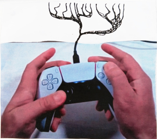
@user.friendly.sounds on Instagram is a special example of this, where a Playstation 5 controller is attached to a custom MIDI setup, triggering janky, off-kilter sounds with any combination of buttons.
instagram
The beauty in it is the repurposing of non-musical, let alone non-professional gear towards the creation of sound art, and this is the whole ethos of circuit-bending, a sound making subculture which thrives in re-wiring (or 'bending') the circuit boards of (usually) cheap, toy instruments.
These experiments, often accompanied with the addition of extra knobs, buttons and distortion circuits, create a wildly different sound than would've been intended by the manufacturer.

My five non-art references looked at objects designed for sound -eliciting human response. Objects such as the Aztec 'death whistle', which through subtle inner tubing, could replicate an anguished human scream; to the hand-operated siren - produce sounds for the purpose of panic - be it for intimidation or as loud a warning as possible.
The Operation board game is by all means an interactive audio sculpture - representative of form, responding to audience stimulus, and producing sound once a circuit is closed.

Other references looked at the fragmentation of sound into non-sound formats. A lecture on the earliest attempts at sound recording details the various pre-20th century experiments - as far back as the 1200s (!) - of capturing the makings of sound.
Patrick Feaster ▶ “Phonogram Images on Paper, 1250-1950” https://youtu.be/TESkh3hX5oM?feature=shared
Similarly, Kevin Purjerer's excellent documentary on Disney's history with animatronics - specifically culminating in the Lincoln animatronic - mentions how magnetic tape, much the same as on a reel-to-reel, was used to feed code into the machines, in turn producing audio sculptures through analog means.
Defunctland ▶ “Disney's Animatronics: A Living History” [https://youtu.be/jjNca1L6CUk?feature=shared]
In other news, I started making the head for my cardboard sculpture, which is always a riveting experience, because it means I grab a hammer and start ripping the ever-loving shit out of some boxes.


0 notes
Note
Hey Xia! Do you know much about JSON Python or C++ I think it is? I've expanded my" research and development" to the VSC or Visual Studio Code. I'm sure you've heard of it. I've discovered a new arduino aswell. The esp32 modules and Dev-kits. They're made by Espressif and they're compatible with various IDEs along with their own. I never knew how much is going on in the computer and microcontroller world!! Anyway, thanks and check out those esp32 products. They are mind blowing! - Thanks-Josh(jshypoo)
Oh hi Josh, hope you're well!! (*~▽~)
Sorry for the late reply, been sick and then got hospitalised then got sick again BUT I'm all well now!
To answer your question, I've heard of JSON Python during my Python module a couple months back but my tutor only briefly touched on the topic, and C++ I've dabbled in the past but soon turned my focus on Python and Java - so yes I have heard of them but haven't dived deep into them yet (≧◡≦)
I'm so glad you're excited about learning so much about the microcontroller world! And I'll definitely check out those esp34 products! Will come in handy for my summer projects!
1 note
·
View note
Photo
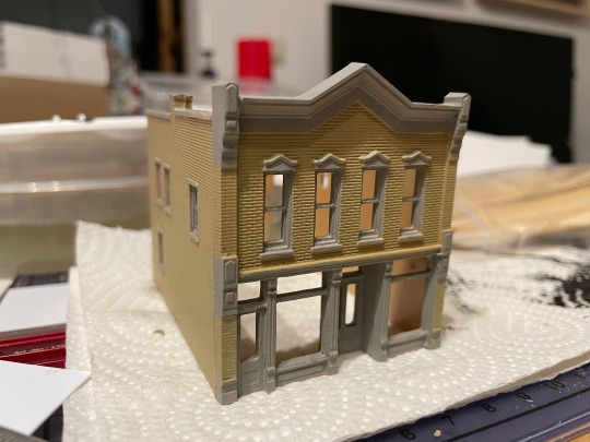
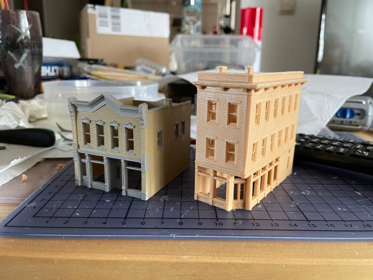

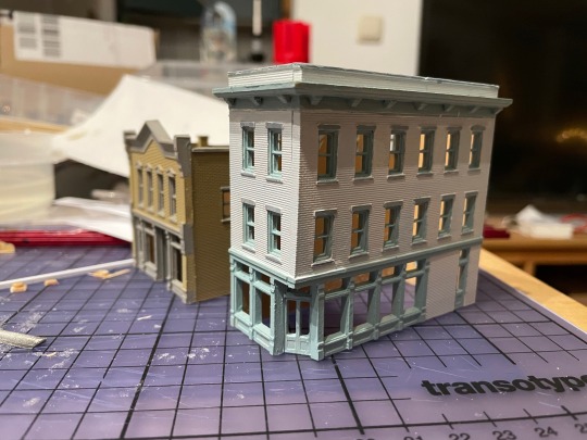
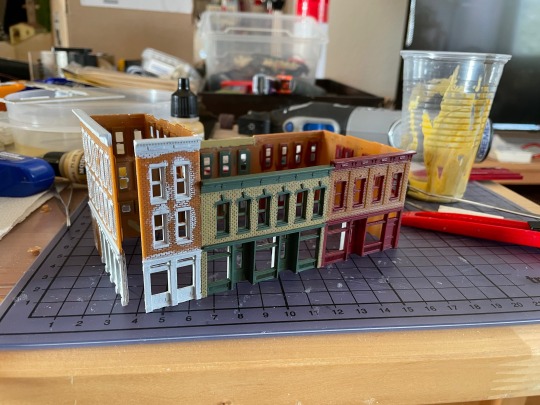
More model railroad content! I’m working on a new T-Trak module which will represent a small american town, and I’ve started by building the houses. None of them are complete yet, but I like how they turned out so far.
The first images are two kits by Woodlands Scenics, under their DPM brand. I’m not really impressed with these kits, since you have to file down parts of the walls and they lack such niceties as, I don’t know, roofs. They do include a piece of plastic; you have to cut out your own roof from that. I’ve shown the painting process of he second house in stages, so you get an idea what the default color of the plastic is. This really doesn’t work at all if not painted.
The final image is an integrated row of houses kit by Walther Cornerstone, in my opinion much better. Only the middle house there is painted yet; for the ones at the ends, I’ve only painted the windows, and will paint the bricks later. Of course it’s not fully assembled yet either.
All of them are made incredibly cheaply compared to german plastic model railroad house kits - even compared to communist-designed ones, and yes, I am speaking from experience here. In particular, the walls and windows are all just one big part, where german sets will have walls with holes, and the window frames will be another part in another color. You can build german kits without painting them at all, though over the years I’ve come to realise that you probably shouldn’t. It looks way, way better if you paint it, even though it is a bit of a pain. It gets better with practice. I’ve used mostly Revell Aqua Color paints here, about half the time straight out of the tub, and the other half mixed together to get a non-standard shade.
I did consider throwing in some coins or similar for scale, but then forgot. The cutting board does have a scale, though: The lines are all one centimetre apart (which means that the distance between the black lines is basically two inches).
The whole module is going to be a longer project. For one, I’m playing with the idea of putting some interior in at least some of these houses, which won’t be trivial in N scale. I’ll definitely put lights in them. The module is also going to have a level crossing, which means I need level crossing gates, and since there don’t seem to be good US level crossing gates commercially available, I guess I’ll have to create a 3D file and send it to Shapeways. And connect some cheap servo motors to make it work, and some LEDs to make it light up. And an Arduino (well, really just a bare ATmega328p) to control all of this and act as a DCC decoder. And so on…
For the record, I’m aiming for about 1950s to 1960s, though I also have a very beautiful Ford Model T from Artitec that’s definitely going to go on there. And I will, of course, absolutely run any and all trains I have along there, no matter from which era or country.
22 notes
·
View notes
Text
Elecrow Crowbits: The Ultimate LEGO-Compatible STEM Learning System That Grows With Your Child
Elecrow Crowbits
9.00 / 10
Read Reviews
Read More Reviews
Read More Reviews
Read More Reviews
Read More Reviews
Read More Reviews
Read More Reviews
Read More Reviews
Read More Reviews
Read More Reviews
Read More Reviews
Read More Reviews
Read More Reviews
Read More Reviews
Read More Reviews
Read More Reviews
Read More Reviews
Read More Reviews

Shop Now
Brick builds, combined with magnetic electronics blocks, and programmable micro-controllers. Does it get any better than this? I think my long search for the perfect STEM learning kit is complete. If you have young children just coming up to the right age for it, the Crowbits system can accompany them throughout their primary education and beyond.
Key Features
Magnetic blocks build circuits
Kits to suit various levels
Specifications
Brand: Elecrow
Development Platform: Scratch and MicroPython
Pros
LEGO-compatible to customize your builds
Full range of components planned
Level up with your child with more complex projects and programmable microcontroller
Familiar Scratch-based programming software
Cons
It's a Kickstarter
Instructions need work expanding on the principles and explanations
Buy This Product
Elecrow Crowbits other
Shop
// Bottom var galleryThumbs1 = new Swiper('.gallery-thumbs-1', { spaceBetween: 10, slidesPerView: 10, freeMode: true, watchSlidesVisibility: true, watchSlidesProgress: true, centerInsufficientSlides: true, allowTouchMove: false, preventClicks: false, breakpoints: { 1024: { slidesPerView: 6, } }, }); // Top var galleryTop1 = new Swiper('.gallery-top-1', { spaceBetween: 10, allowTouchMove: false, loop: true, preventClicks: false, breakpoints: { 1024: { allowTouchMove: true, } }, navigation: { nextEl: '.swiper-button-next', prevEl: '.swiper-button-prev', }, thumbs: { swiper: galleryThumbs1 } });
Take a moment to imagine the perfect electronics and engineering learning kit. It would be so simple even a child could use it: magnetic blocks, perhaps? Modular, so you could swap bits in and out to modify projects. It would scale up, so you could start with simple circuits and move on to programmable hardware, catering to all levels of the curriculum. Lastly, I'd throw in LEGO-compatible, because LEGO bricks are the best tool for creativity and engineering ever made.
That's exactly everything the Elecrow Crowbits system is, and it's crowdfunding now.
youtube
Disclaimer: This is a Kickstarter
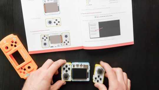
Four of the five available Crowbits kits were sent to us for evaluation during the Kickstarter, however, they are still very much in the prototype stage, and we've evaluated them on that basis. Some bits were missing, some were non-functional, and the software is still a work-in-progress. This is to be expected at this stage, but the core system is solid.
Also, the usual Kickstarter caveat applies: your money is at risk, and there's no legal obligation with any crowdfunding campaign to actually deliver a product. That said, this isn't Elecrow's first campaign (the CrowPi 1 and CrowPi 2 were a huge success). It's a well-established company with a reputation to maintain and a good track record, so we think the risk is minimal.
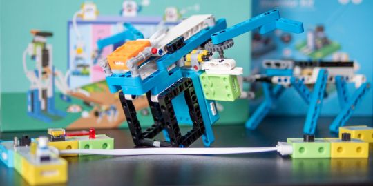
What Are Crowbits?
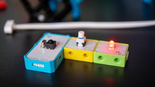
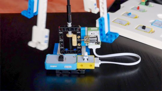
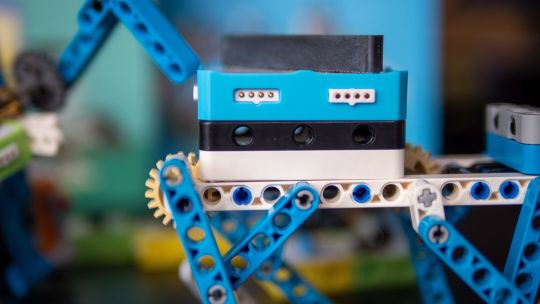
Crowbits modules are magnetic electronics blocks with LEGO-compatible pin holes on the side and stud holes underneath. The 4-pin pogo connections are either male or female, and have a small protrusion on the bottom to prevent wiring them the wrong way around.
Extension cables enable you to place a module elsewhere, and these too feature the same magnetic connection and can't be plugged in the wrong way. The whole system operates on a safe, low voltage, and with rechargeable battery blocks that charge over micro-USB.
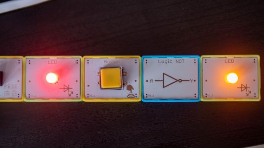
Each Microbits module is color-coded for ease of understanding:
Blue modules are power and logic. In the basic sets, these are simple battery modules that don't require programming. In more advanced sets, these are programmable microcontrollers with pin numbers on the connections for addressing modules directly.
Yellow modules are inputs: buttons, basics sensors and such.
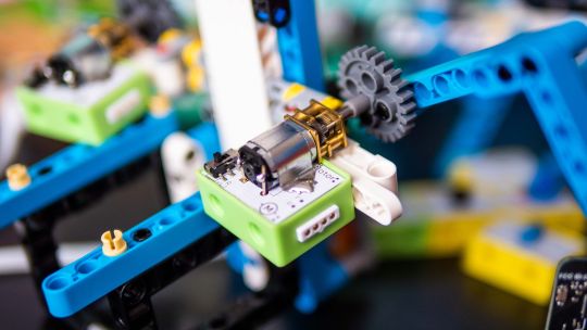
Green modules are outputs: LEDs, motors, buzzers, relays.
Orange modules are special and require serial communication lines to the programmable hub. These include things like color sensors, joysticks, or 2G communications hub.
A large range of Crowbits modules are planned, though these will be available separately at a later date. For now, you can only purchase the full Crowbits kits with their included module selections.
No Programming Required!
Since the first two Crowbit kits require no programming, how does that work? Simple, as long as you follow some basic rules:
Yellow input modules must be placed on the left of green output modules (when viewed with the module name being on the top, and symbol in the bottom right).
One input module can control a chain of output modules.
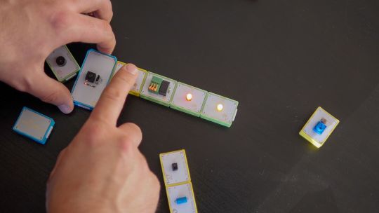
A new input-output chain will be created if you add another input module to the right.
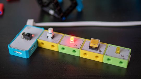
Blue battery modules can go anywhere in the circuit, and their orientation doesn't matter as long as the pins are compatible.
With this, kids can create basic circuits. For more complex circuits (that still don't need programming), a series of bitwise logic operator modules are planned. A "NOT" logic gate is included in the Hello kit, and more will be available later.
This enables you to reverse an input, such that a button that would normally turn on an LED, would now function as a button to turn the LED off.
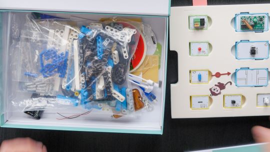
Crowbits Kits
The Crowbits Kits are divided into five stages of increasing complexity, but all share a common system and are compatible with each other. Some modules are duplicated between kits. Let's take a look at the contents and direction of each kit.
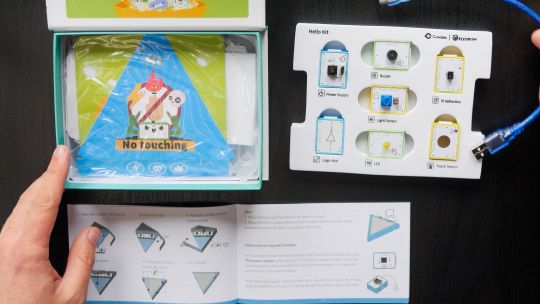
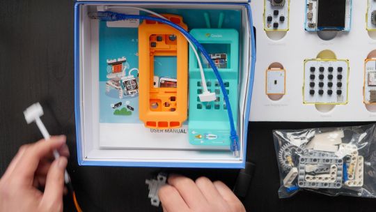
Hello Kit
The most basic of kits is also the cheapest, available for $30. It includes seven modules, one of which is a small battery module. Five project builds are included along with pre-cut cardboard parts to stick together. No programming is required, and the Hello kit is suitable for ages 5-6.
Explorer Kit
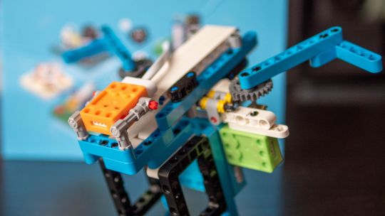
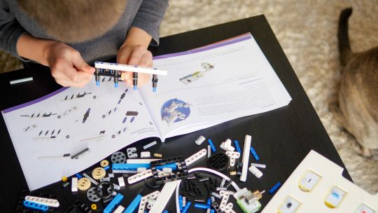
The Explorer Kit continues the no-programming theme, but adds movement through the use of a motor module and pack of technic pieces for some basic engineering. A total of eight modules are included, one of which is a medium-sized battery pack. The build guide contains a mix of brick-based and cardboard projects. With a little adult supervision on the trickier mechanical elements, 7-8-year-olds should be able to handle this kit. The Kickstarter price is $80, rising to $130 RRP.
Inventor Kit
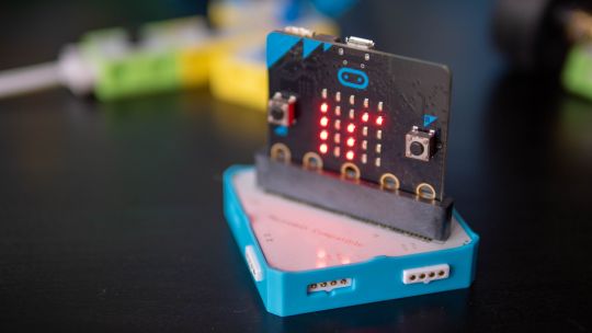
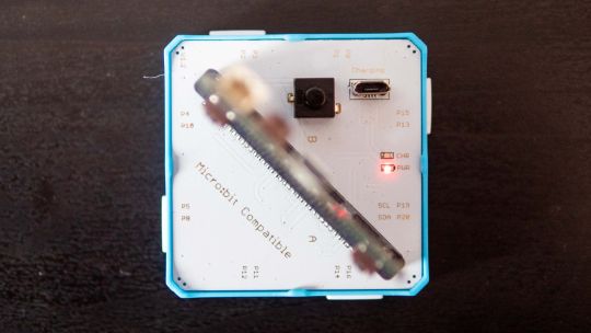
The Inventor Kit is a big step up that introduces programming concepts and more complex mechanical engineering. The main module of this kit requires a BBC Micro:bit (v1) to function. This is not included, though it may be available as an add-on if you don't already own one.
For those not familiar, the BBC Micro:bit is an all-in-one programmable microcontroller specifically designed for use in the school curriculum. It's widely used in UK schools, and gaining ground in the US.
Related: 10 Beginner Projects for the BBC Micro:bit
Ten modules are included as well as a large pack of technic bricks, suitable for building projects such as an obstacle avoidance car or color-sorting robot.
Given the use of BBC Micro:bit and Scratch programming in schools from around age 8, this kit would be suitable for 8-12 year-olds. It's available during the Kickstarter for $90, RRP $130.
Creator Kit
This was not yet ready for review at the time of writing, but the core of the Creator kit is an Arduino-based board, and includes 11 modules more suited to smart home projects and more complex interaction programming, along with a small selection of technic blocks. There are no movement motors. The Creator kit is available for $100 now, or RRP $150 later.
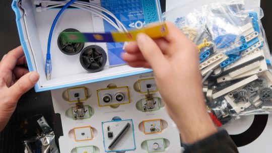
Master Kit
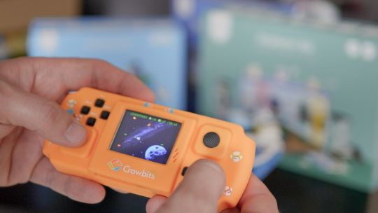
The most advanced kit in the range, the Master Kit uses an ESP32-based board at its core, featuring a TFT color screen. Also in the kit are some joystick modules, a small keyboard, laser ranging sensor, and 2G connection.
The Master Kit has a small number of technic bricks, and as well two silicone cases for a working phone, and a retro game console. It's designed to show the modules coming together to create a finished product. However, programming the firmware is quite complex, so I'd rate this kit as suitable for 14 and up. The early pricing is $100 for the Master kit, rising to $150 RRP.
LEGO-Compatible, not Actual LEGO
I should note that the Crowbits kits are not an officially endorsed nor licensed LEGO group product, and do not contain actual LEGO bricks. Instead, the LEGO-compatible technical bricks carry the brand name "CaDA", which I've not come across before.
That said, the bricks are well made and connect simply and securely, which is always a worry with off-brand construction bricks. For context, you can buy a set of at least 500 CaDA technic bricks on AliExpress for under $30.
You can of course decorate the builds with your own real LEGO, should you wish.
As a nerdy side-note, be warned that the instruction for the brick builds are read left-to-right, rather than top-to-bottom. If you're a LEGO family, this is mildly infuriating and means your child might skip steps!
Programming with LetsCode
Programming your Crowbits kits is done using Elecrow's new LetsCode (currently only for Windows, but support is promised for Mac OS and Raspberry Pi later).
LetsCode is a customized version of Microsoft MakeCode, which is itself based on the graphical block programming language, Scratch 3.0. As such, it'll be immediately familiar to anyone with experience of Scratch programming. It's widely used for introductory programming classes all over the world, and includes graphics blocks for all common concepts like loops, branching, and functions.
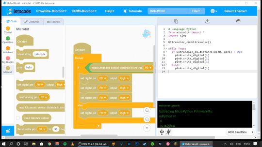
Pin numbers are printed directly on the blue modules, so it's easy to see which component is attached where.
If you outgrow graphical programming, you will also be able to program in MicroPython or Java, though this was not supported at the time of testing.
Should You Back the Elecrow Crowbits?
The Crowbits magnetic circuit system is easy to use and scales well for different ages and user levels. You can start with simple circuits, and move on to programmable logic controllers, and still reuse all the bits. It's a system that will grow with your child throughout their learning journey from age 6 to 14. Very few educational toys can make that sort of claim.
If you want your child to have a competitive edge in the programming, electronics, and engineering aspect of the STEM curriculum, then supplementing schoolwork is a great idea.
Even though many schools have now returned, it's possible you've opted to fully homeschool or just want to supplement their existing classwork. Over the next few years, schools will inevitably be different. There'll be a lot less practical work going on because of the aspect of touching shared equipment, so having this sort of kit available at home with software that's familiar will be of great benefit.
That said, the Crowbits kits vary greatly. If you're a completionist, you can grab a bargain bundle during the Kickstarter of every Crowbits kit available, for a cool $400 (rising to $600 RRP after the campaign).
But I think the best value comes from the Explorer, Inventor, and Master Kit bundle for $270. This includes a ton of mechanical bricks and plenty of movement modules. The BBC Micro:bit compatibility ties in perfectly to the existing curriculum (in the UK, anyway), while the ESP32 board is a good step up once they're old enough.
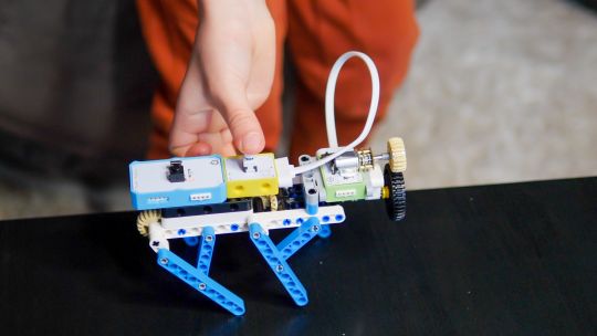
If you're only going to purchase one kit, I'd recommend skipping the Hello kit and going straight to Explorer or Inventor, depending on whether you want programming introduced yet. The cardboard projects in the Hello kit just felt a little too contrived and didn't engage my 6-year-old son in the same way LEGO does.
While the mechanical elements of the Explorer kit may need a little adult supervision, he was quite capable of the bulk of construction and able to use the LetsCode software thanks to previous experience with Scratch.
On the other end of the scale, I wasn't overly impressed with the Master kit either. The game console project, while it produces a cool end product, consists of simply the main board and two joystick modules on the side.
There is no construction, and the hardest part is loading on firmware, which tedious at best. The phone project is also impressive but limited to a 2G network, many of which will be disabled by the time the Crowbit kits ship. The ESP32 mainboard is technically impressive, but once your teenage child is ready to program this thing, the magnetic block system may not be appropriate anymore. It's a good addition to your collection if you're purchasing the earlier sets too, but I wouldn't purchase it alone.
Overall though, I think my long search for the perfect STEM learning kit is complete. If you have young children just coming up to the right age for it, the Crowbits system can accompany them throughout their primary education and beyond. And when they're done with it in a decade, we'll probably all be learning in VR anyway.
Alternatives to Crowbits
Crowbits isn't the only STEM kit around. The closest competitor is the littleBits STEAM kit, which retails at around $400, doesn't include any technic bricks, and has a limited selection of magnetic modules. It's more closely aligned to the US curriculum though with more extensive teaching materials, and already in use in many schools.
The LEGO groups' own Robot Inventor MindStorms kit is also worth considering, retailing at $350. It's focused more on robotics than basic electronics, and isn't suited to younger children, but the software is also based on Scratch. It would make a great step once your child reaches 14, and has outgrown the magnetic Crowbits system.
Elecrow Crowbits: The Ultimate LEGO-Compatible STEM Learning System That Grows With Your Child published first on http://droneseco.tumblr.com/
2 notes
·
View notes
Text
ATOMSTACK A5 20W Simplifies Laser Engraving
Lser cutters and engravers keep getting cheaper, which is why I decided to give it a shot. A few days later, I received the Atomstack A5. This is a 20 W laser engraver, not a cutter, although it can cut plywood up to four or five millimeters or so. Also, officially, it's not suitable for metal, as it seems to be able to engrave aluminum alloys as well.
A5 is a kit of parts that you have to assemble yourself. It's not very difficult, and all the tools it needs are included in the kit. These six steps will take about 30 minutes in total to complete, and you'll have a good, sturdy assembly. It's all solid aluminum with no plastic parts.
Make sure the seat belt is properly tightened. Not too tight, not too loose, you want a smooth glide. The same goes for the guide wheel in step 5. If it's too tight, you might feel a click when moving the X-axis; if it's too loose, things might start to wiggle. The laser head also has guide wheels, which may also need adjustment.
The software LaserGRBL that controls the Atomstack A5 20W is free. There's also LightBurn, which isn't free, but has a time-limited, fully-featured free trial. Once you get the hang of your engraving machine, you might want to give it a try.
The installation manual included with the kit does not explain how to use the engraver, nor does the Atomstack website. The LaserGRBL tool, by the way, is an open source tool developed by arkypita, not related to Atomstack, it helps itself, but also doesn't provide real guidance. Instead of searching YouTube for tutorials, I decided to try and solve the problem myself.
After connecting the A5 to my Windows 10 computer, I noticed that it requires a CH340 USB-to-serial converter driver. However, you don't have to search for it online, as it's conveniently included in LaserGRBL's Tools menu.
There is also an option to upload firmware, which is possible because the Atomstack control hardware is actually a custom Arduino running the popular open source g-code interpreter GRBL. That's great news for manufacturers and hackers, as there's nothing proprietary inside the A5.
As a first attempt, I repeated the plywood cutting benchmark shown in the video on the LaserGRBL website. I loaded the example graph in LaserGRBL and hit the play button. After a few minutes, I cut out a circle (along with some plastic sample material) from a small piece of plywood included in the A5 kit.
Engraving an image on a piece of wood is a bit difficult. Engraving is easy to get started, but getting something right takes practice and experimentation. However, after a few bad and burnt sculpts, I managed to get a clean result.
The trick is to consult the materials database built into LaserGRBL. It has a section on the Atomstack A5 20W that recommends setting the laser power to 28% for the wood. Using this value with constant power instead of dynamic power produces beautiful results. Also, it is important to focus the laser by moving the head up and down.
I highly recommend doing all this in a well-ventilated room, or better yet, outside (as I do). Laser engraving works by burning the material, so there are various toxic levels of fumes that you don't want to breathe in. Also, please wear goggles!
The Atomstack A5 Laser Engraver is a complete kit that includes tools, green goggles, and even some sample materials for practice. Assembling this kit is easy and, if done correctly, results in a sturdy, sturdy tool with smooth sliding X and Y axes and a stable head.
Adjusting the height of the head might be a little more comfortable, but probably not at this price point, and the fan is a bit noisy.
The A5 relies on Arduino and third-party open source software to control it, so by adopting the A5, you're not stuck in half-baked buggy programs that will never be updated. The software is easy to use and you can start sculpting right away.
atomstack a5 30w
1 note
·
View note
Photo

This week we were tasked to find a creative application for digital input and output. Wiring up the LCD screen that came with my Arduino kit, along with a potentiometer, I was able to code (see below) this message to send to my family. There are many wires in this one, so knowing where each wire goes and securely connecting them is very important.
Code:
#include <LiquidCrystal.h> // includes the LiquidCrystal Library LiquidCrystal lcd(12, 11, 5, 4, 3, 2); // Creates an LCD object. Parameters: (rs, enable, d5, d4, d3, d2) const int switchPin = 6; int swittchState = 0; int prevSwitchState = 0; int reply;
void setup() { lcd.begin(16, 2); // set up the LCD's number of columns and rows lcd.print("Enjoy Florida!"); lcd.setCursor(0, 1); lcd.print("Love, Daniel <3");
}
void loop() { // Turn off the display: lcd.noDisplay(); delay(300); // Turn on the display: lcd.display(); delay(2000); }
0 notes
Photo

Arduino Workshop for Beginners - Tutorial
Welcome to the Arduino Workshop, where you’ll be able to follow our guided course which covers everything you’ll need to know in order to create your own Arduino projects and become a leveled up maker. My name is Sam and along with being a maker myself, I also enjoy teaching others how to use different technology and create amazing projects. Along with the course videos themselves, you can find all of the related course material such as code examples, circuit diagrams, images, and other resources. We’ll be working with Arduino so you’ll need an Arduino board to follow this course. We’ll be introducing many different concepts including working with various types of hardware such as sensors, displays, and general electronics components, and the kit we’re using for all of this is the Sparkfun Inventors Kit. If you are not in Australia, you can grab from Sparkfun directly and have it shipped to you almost anywhere in the world. Course Goals: Understand what an Arduino is and how it works Learn how to use an Arduino safely Program your Arduino using code that you’ve written in the Arduino IDE (Integrated Development Environment) Learn programming concepts using C and C++ along with Arduino specific programming Understand best practice concepts for programming and prototyping Use a wide variety of hardware and components and prototype your projects using a breadboard Build your own innovative project with Arduino When you’re ready, let’s begin the Arduino Workshop! If you run into any issues throughout this workshop, then please reach out to us on our forum. We’re full-time makers and are here to help. Chapter 1: Introduction to Arduino 1.0 Chapter Overview In this chapter you’ll learn about: What is Arduino Different types of Arduino boards How does the Arduino Uno board work and why it’s so popular What is a microcontroller How to use the Arduino IDE (Integrated Development Environment) Powering and connecting your Arduino to your computer Uploading programs to your Arduino board By the end of this chapter, you will have uploaded your first program to your Arduino board to control an LED. 1.1 What is Arduino? In this section, we look at what is Arduino, what it’s good for makers, and some of the different types of Arduino boards available. Section Resources: Example Arduino Uno Variations 1.2 What is a Microcontroller? In this section, we’ll be looking at what is a microcontroller (the chip at the heart of any Arduino board), an overview of how they work, and how it integrates with the Arduino environment. 1.3 The Arduino Uno In this section, you’ll learn about the features and capabilities of the Arduino Uno board, how the layout of the board can affect your project, and why the Uno is such a great all-rounder. 1.4 Arduino IDE and the Language In this section, we’ll take a look at the Arduino IDE, which is where you write the code for your Arduino, upload it, and communicate with your board. We’ll also cover the programming language that Arduino IDE uses, and where to download it. Section Resources: You can download the Arduino IDE from the Arduino website. 1.5 Powering and Connecting Your Arduino In this section, you’ll be learning about the various ways to power your Arduino, and how to connect it up to your computer for uploading your programs, and communicating to the computer using the serial port. Section Resources: Arduino Power Layout 1.6 Hello World Example In the final section of this chapter, we’ll talk through using the Arduino IDE to upload your first program to your Arduino board. Section Resources: Source code for ‘Hello World’ void setup() { pinMode(13, OUTPUT); //setup pin 13 as an output } void loop() { digitalWrite(13, HIGH); // turn the LED on (HIGH outputs 5V) delay(500); // wait for 500 milliseconds digitalWrite(13, LOW); // turn the LED off (LOW outputs 0V) delay(500); // wait for 500 milliseconds } Chapter 2: Using Inputs and Outputs 2.0 Chapter Overview In this chapter you’ll learn about: How to properly structure your code Using variables to write more capable programs Building circuits using a breadboard Reading inputs and controlling outputs using the digital and analog pins Communicating via the serial port By the end of the chapter, you will have created an input interface for your Arduino, using the Serial Monitor to display the data. 2.1 Program Structure In this section, we’ll be learning about how to properly structure code using indentations, nested levels, and semicolons. Section Resources: Example Program Structure 2.2 Using Variables In this section, we’ll explore the use of variables, which will allow you to write more sophisticated code. Section Resources: Arduino Reference Datatypes: If you’re interested in learning more about the various datatypes that Arduino supports, check out the reference page. 2.3 Building Your First Circuit Using a Breadboard In this section, we’ll look at using different components such as LEDs, buttons, jumper wires, resistors, and a breadboard to construct a circuit. Section Resources: Further Reading If you’d like to know more about how electronic components work, check out the Analogue Electronics Crash Course and All About LEDs tutorials for more in-depth information. Wiring Diagram 2.4 Using Digital Pins In this section, we’ll learn how to use the digital pins to read inputs and control outputs. Section Resources: Source code for ‘LED Button’ int buttonPin = 2; int ledPin = 3; void setup() { // setup pin modes pinMode(ledPin, OUTPUT); pinMode(buttonPin, INPUT_PULLUP); } void loop() { // read state of buttonPin and store it as the buttonState variable int buttonState = digitalRead(buttonPin); // write the value of buttonState to ledPin digitalWrite(ledPin, buttonState); } Wiring Diagram for ‘Digital Pins’ 2.5 Using Analogue Pins In this section, we’ll learn how to use the analog pins to read inputs and control outputs. Section Resources: Source Code for ‘Blink Rate Control’ int ledPin = 3; int potPin = A0; void setup() { // setup pin modes pinMode(ledPin, OUTPUT); pinMode(potPin, INPUT); } void loop() { // read the value of the pot and store it as potValue int potValue = analogRead(potPin); // turn led on and wait for the time equal to potValue digitalWrite(ledPin, HIGH); delay(potValue); // re-read the value of the pot and store it as potValue potValue = analogRead(potPin); // turn led off and wait for the time equal to potValue digitalWrite(ledPin, LOW); delay(potValue); } Source Code for ‘LED Brightness Control’ int ledPin = 3; int potPin = A0; void setup() { // setup pin modes pinMode(ledPin, OUTPUT); pinMode(potPin, INPUT); } void loop() { // read the value of the pot, divide it by 4, and store it as potValue int potValue = analogRead(potPin) / 4; // turn led on with the value of potValue analogWrite(ledPin, potValue); } Wiring Diagram for ‘Analogue Pins’ 2.6 Displaying Information Using the Serial Port In this section, we’ll be looking at using the serial port on the Arduino to communicate with a computer via USB. Section Resources: Source Code for ‘Serial Monitoring’ int ledPin = 3; int buttonPin = 2; int potPin = A0; void setup() { // setup pin modes pinMode(ledPin, OUTPUT); pinMode(buttonPin, INPUT_PULLUP); pinMode(potPin, INPUT); // initialise serial port with baud rate of 9600 Serial.begin(9600); } void loop() { // read the state of buttonPin and store it as buttonState (0 or 1) int buttonState = digitalRead(buttonPin); // read the value of the pot, divide it by 4, and store it as potValue int potValue = analogRead(potPin); int filteredPotValue = potValue / 4; // turn led on with the value of potValue analogWrite(ledPin,filteredPotValue); // print the value of the button Serial.print(
0 notes
Text
Sharing Arduino Education courses is easier than ever
Over the past few years, Arduino Education has expanded, offering new learning solutions to teachers and students around the world. Today, we have more than 10 kits with exciting online courses for STEM teachers and learners ranging from middle school to university.
When creating these products, we were delighted to collaborate with many brilliant educators, who shared with us their unique teaching styles and provided valuable feedback.
With the pandemic dramatically shaking up the status quo in education, we now have more learning styles than ever. From large schools using hundreds of Arduino kits to smaller classes and study groups. There are even a lot of parents who use kits for homeschooling, along with an increasing numbers of self-learners.
We’re excited to see Arduino Education products being enjoyed in so many different ways, and want to make sure our kits are easy to use and share in every situation. That said, we’re excited to announce several changes to how our educational products are shared.
Personal courses vs. Classroom courses
From now on, when you register an Arduino Education kit, the online courses associated with it will be added to your personal collection, accessible via “My Courses” in the profile menu. Courses in your personal collection are only visible to you. This way, if you’re learning by yourself, you have a quick and easy way to access all your learning resources in one place.
If you’re learning together with others, or you’re an educator managing a group of students, you can now set up a classroom. This will create a second collection of products which you can share with other people. You can switch between the different product collections anytime, and transfer products between them.
Setting up a classroom
Setting up a classroom takes a matter of minutes. Simply add a few details about yourself and your teaching environment and choose which products you want to share with others.
Once your classroom is set up, you can start inviting students and other educators to join.
Everyone who joins will immediately get access to all online courses that you add to your classroom.
Using the classroom system, you can now share any Arduino Education product with any number of people, and as the classroom admin, you are in full control of who can access your courses, meaning you can add and remove new members anytime.
Teacher and admin roles
When you set up a classroom, you become its admin. You have the power to change settings and control the member list and available courses. When you invite your colleagues, you can choose if they should also be an admin, or take the teacher role.
Teachers can add and remove students from the classroom, but cannot manage other educators or change classroom settings. Both admins and teachers will see the educator version of the online content, with educator tips, logbooks and more. Roles can be changed whenever you need, and you can have multiple admins at the same time.
We hope these changes will provide better administration possibilities to institutions with multiple collaborating educators.
Safety for our youngest learners
When working on these updates, we wanted to make sure that the system is usable and safe even for our youngest users. If your students are too young to have an inbox, you can invite them by sharing a classroom code. This way, they can join your classroom without using an email address.
If your students are under the age of 14, you can also be sure they’re in a safe online space. They’ll only encounter child-safe content, and their accounts will be anonymized, with no personal data collected.
We hope these changes will make learning with Arduino Education easier, safer, and more flexible, and we can’t wait to share with you what’s coming next!
If you have any questions or feedback, don’t hesitate to get in touch with us. Head on over to Arduino Classroom right here.
Happy learning!
The post Sharing Arduino Education courses is easier than ever appeared first on Arduino Blog.
Sharing Arduino Education courses is easier than ever was originally published on PlanetArduino
0 notes
Text


Final Project: Sensor Controlled Pet Feeder
List of components used:
UNO R3 Controller Board
Power Supply Module
Servo Motor SG60
Ultrasonic Sensor
830 Tie-Points Breadboard
9V Battery / 9V1A Adapter
Female-to-Male Dupont Wire (x5)
Jumper Wire (x2)
Technical Description:
When considering what I should create for my final artefact for this module, I struggled narrowing down what I could do within this immense world of physical computing. Eventually, I decided to build upon the small experiments I have completed and combine the skills and knowledge that I have learnt throughout this module with something that I am passionate about. I wanted to incorporate my love for animals and my pets into my project, so I decided to create a sensor controlled pet feeder.
Obviously this is not the first time that such a thing has been created so my idea is not relatively groundbreaking but that was never my intention. I found many examples on YouTube of people who have created similar artefacts and have included in my references those that have influenced my project the most.
Initially I had planned to create the pet feeder for my dog, Kiara, however after much trial and error I soon realised that the feeder itself was too small and the food for my dog was too heavy for the artefact to be used to its full potential. Video evidence of my dog with the automatic pet feeder can be found in the google drive link below. So I set my sights on something smaller and decided to try the automatic pet feeder with my two rabbits; Snowdrop and Bluebell. As you can see from the video provided in this post the artefact was more successful. When experimenting the feeder with my dog I learnt that the cardboard pathway that released the food was too flimsy along with the handle on the servo motor. I decided to make adjustments before trying with my rabbits and made a more reliable pathway out of stronger cardboard and used a small wooden stick instead of cardboard for the handle.
As for the wiring and more technical aspects of the automatic feeder I adapted the initial tutorial that I had found on YouTube. I came to the conclusion that I needed to wire a power supply module on the breadboard to provide power to the servo motor as well as the motion sensor simultaneously. Initially, I used the 9V battery provided within the kit but after much use it slowed the servo motor down until it stopped working completely. I changed the power source to the 9V1A adapter which solved the issue however did limit the portability of the feeder itself.
Whilst using the feeder I soon realised that it is essentially useless when the food is not lying above the servo motor handle as instead of falling into the pathway it is simply swept aside inside the box. I also had to have a small gap cut into the food compartment to fit the breadboard and power supply module, this could have been improved by using a larger cardboard box for the feeder.
Overrall, I am pleased with the outcome of my artefact. I enjoyed wiring the components together to create something useful and interesting. Although there is much improvement that could be done, essentially it did work and released food for my rabbits. As for how I would improve the feeder if I were to come back to this project; I would most certainly use a larger cardboard box and a bigger battery for ease of use and placement.
Relevant links:
https://letsmakeprojects.com/arduino-automatic-pet-feeder/
https://letsmakeprojects.com/how-to-make-arduino-toll-tax-barrier/
https://www.youtube.com/watch?v=zQ8SjIcYC5w&ab_channel=jeevanjee
Code:
#include <Servo.h> //servo library
Servo servo;
int trigPin = 2;
int echoPin = 3;
int servoPin = 9; //pin choice is yours
long duration, dist, average;
long aver[3]; //array for average
void setup() {
servo.attach(servoPin);
pinMode(trigPin, OUTPUT);
pinMode(echoPin, INPUT);
servo.write(0); //close cap on power on
delay(1000);
servo.detach();
}
void measure() {
digitalWrite(trigPin, LOW);
delayMicroseconds(5);
digitalWrite(trigPin, HIGH);
delayMicroseconds(15);
digitalWrite(trigPin, LOW);
pinMode(echoPin, INPUT);
duration = pulseIn(echoPin, HIGH);
dist = (duration/2) / 29.1; //obtain distance
}
void loop() {
for (int i=0;i<=2;i++) { //average distance
measure();
aver[i]=dist;
delay(50); //delay between measurements
}
dist=(aver[0]+aver[1
]+aver[2])/3; //average distance by 3 measurements
if ( dist<15 ) {
//if hand on the distance 10...15 cm
servo.attach(servoPin);
delay(1);
servo.write(150);
delay(3000); //wait 5 seconds or u can change this value
servo.write(0);
delay(1000);
servo.detach();
}
}
0 notes
Text
Experiment #2 : The Icarus Servo
Experiment conducted 2021/03/02
In this experiment I actually tried a series of things. First I tried controlling the brightness of an LED with a potentiometer. When that didn't work, I replaced the LED with a servo motor instead. At the end, I replaced the potentiometer with a photoresistor to the servo. I attached it to the arm of the servo and attempted to create a program that would make the servo move the resistor towards the brightest light reading it could find. I like to call it the Icarus Servo!
Part 1: Potentiometer Controlled LED
How the Potentiometer Works
The potentiometer has three pins - two terminal pins and one wiper pin. The terminal pins connect to the live and ground wires. Internally, these terminals are connected to each other along a track. A wiper connects to the middle of the track, where its position along the track rotates with the potentiometer's dial. This essentially makes the two sides of the track variable resistors, and the whole track a potential divider circuit - whose signal can be read from the wiper pin. (Fun fact: Because of how the potentiometer works, it doesn't technically matter which way around you connect the terminals!) If you're curious about potentiometers, Jeff Feddersen has a clear and concise explanation on their website.
For this experiment, we can read the signal from the wiper pin into the Arduino, and then use code to output a voltage to the LED. More voltage means more light!
Components Used
This experiment uses the Arduino UNO R3 Project Starter Kit.
1 x UNO R3 Controller Board (the Arduino)
1 x Breadboard
Breadboard jumper wires
1 x Potentiometer
1 x LED
1 x 220Ω resistor
The Wiring
The Code
void setup() { pinMode(7, OUTPUT); // LED ouput Serial.begin(9600); } void loop() { int val = analogRead(A0); // Potentiometer input int out = map(val, 0, 1023, 0, 255); // Converts the input range of the potentiometer (0-1023) to the output range of the analog pin (0-255) analogWrite(7, out); // Write to the LED output Serial.println(out); delay(10); }
You can see all the code for this experiment on GitHub.
The code here takes the signal from the potentiometer via pin A0, and outputs the signal to the LED on pin 7. The potentiometer input is a 10-bit value (in the range 0-1023), but the output pin is only an 8-bit output (in the range 0-255). For this reason, we use the map function to convert the value from the input range into the output range, so that we can use the input to control the LED.
There you have it! But not really...
I set it up in TinkerCAD and it worked a treat! Then I set it up my physical kit, and it didn't work.
The LED only switched between full brightness and completely off, with not even the smallest zone of "inbetween". After double checking the wiring, plotting potentiometer readings in the IDE's serial plotter, and switching out the LED for every colour in the kit, I discovered that the LEDs provided in this kit don't fade!
So let's connect it to a servo instead. Much more fun!
Side note: It took me a moment to realise you need to assemble the potentiometer yourself. The two parts you need are in the small box with eight smaller compartments, specifically they're in the top compartment second from the right.
Part 2: Setting Up the Servo
How the Servo Works
A servo motor is a particular kind of motor that, though only able to rotate in a 180°, uses a potential divider circuit to know it's position at all times. Using the Arduino we can send a target state to motor, and then it will compare the target state of the potential divider to it's actual state to determine how to drive the underlying DC motor. GreatScott! on YouTube has a great video that does more in-depth on how servos work, and even how you can modify them to have more degrees of rotation.
Components Used
This experiment uses the Arduino UNO R3 Project Starter Kit.
1 x UNO R3 Controller Board (the Arduino)
1 x Breadboard
Breadboard jumper wires
1 x Potentiometer
1 x Servo Motor (SG90)
The Wiring
I removed the LED and wired up the servo instead. The brown wire connects to ground, the red to live, and the orange to our control signal from the Arduino. I used pin 9.
The Code
I first ran example code that comes with the Ardiuno IDE to test the servo was working. You can load the example by going to File > Examples > Servo > Sweep. My wiring worked! I then wrote a program to use input from the potentiometer instead.
#include Servo servo; void setup() { servo.attach(9); // Servo output Serial.begin(9600); } void loop() { int val = analogRead(A0); // Potentiometer input int out = map(val, 0, 1023, 0, 180); servo.write(out); // Write to the servo output Serial.println(val); delay(15); }
You can see all the code for this experiment on GitHub.
Like in our LED example, I use the map method to translate the value from the input range to the output range, but this time the output range is 0-180, the rotations in degrees our servo can handle. The Ardiuno kindly abstracts away converting that value into the electrical signal the servo actually wants.
There you have it! Sort of...
youtube
Can't see the video? Watch it on YouTube!
Judging by the plot of the potentiometer signal, it seems that as the potentiometer and other components wobble about, it sends a somewhat volatile signal, hence the weird movement from the servo. Blu-tacking the potentiometer to the breadboard helped to minimise that. It worked well enough for my purposes, and I was curious to try what I've now dubbed the Icarus servo!
Part 3: The Icarus Servo
Components Used
This experiment uses the Arduino UNO R3 Project Starter Kit.
1 x UNO R3 Controller Board (the Arduino)
1 x Breadboard
Breadboard jumper wires
1 x Photoresistor
1 x 5KΩ resistor
1 x Servo Motor (SG90)
The Wiring
I replaced the potentiometer with a photoresistor, in the same setup I used in my first experiment. To begin with, I just set it up on the breadboard, as to test that it was working. I wired the output of the potential divider to pin A0 so I could reuse the code I was currently using.
The photoresistor was not giving a huge range of values, certainly not the full 0-1023 range theoretically possible. Replacing the 10KΩ resistor I was originally using with a 5KΩ resistor helped increased the range. After that however, I just used the serial plotter to see what range of inputs the sensor was giving me, and updated my map function call to work in this range instead.
int out = map(val, 10, 360, 0, 180);
To make my Icarus servo, I wanted to attach the photoresistor to one of the servo motor arm attachments. To ensure that the photoresistor wouldn't swing into the side of the servo, I used code to set the servo to 0 degrees, then attached the servo arm such that it would swing around the "outisde" of the servo i.e. keep clear of the blue box. I then slotted the photoresistor into the servo arm and connected it to the breadboard using plug-to-socket jumper wires.
The Code
I wanted my servo to move the arm areas of light. My simple approach to this was to create a hill climbing algorithm. The program stores a current position in variable, and then continually rotates slightly to either side of this position to see if either of them produce a higher light reading than the current position. If they do, the current position is updated to the new one.
#include Servo myservo; int pos = 0; void setup() { myservo.attach(9); // Servo output Serial.begin(9600); } void loop() { int highestLightLevel = 0; int newpos = pos; for (int i = -1; i <= 1; i++) { // Iterates i through the values -1, 0, 1 - corresponding to "left", "centre", and "right" // Calcuate next position to take a light reading from int testpos = pos + i * 5; if (testpos < 0) testpos = 0; if (testpos > 180) testpos = 180; // Move to that position myservo.write(testpos); delay(200); // The the servo time to reach it's target before taking a light reading // Take a light reading int light = analogRead(A0); // Photoresistor input // If that reading is the highest so far, save it and the tested position to refer to later if (light > highestLightLevel) { highestLightLevel = light; newpos = testpos; } } // Update the "current" position of the servo to the one that produced the highest light reading pos = newpos; Serial.println(highestLightLevel); }
You can see all the code for this experiment on GitHub.
There you have it! For real this time!
youtube
Can't see the video? Watch it on YouTube!
While recording the video I had my phone torch on, which I used to encourage the servo to move in particular directions. Sometimes the jumper wires would push against it, but otherwise it worked reasonably well! Working on this experiment in particular, I was surprised to see just how prevalent potential divider circuits are in electronics.
On reflection, I think part of why the movement of the servo is so janky is that each time the code pulls a signal from the photoresistor, it only takes one reading, meaning ambient variations in reading can cause the servo to move in different directions essentially at random. Taking an average reading over a few milliseconds would help prevent against this. It was definitely good insight onto how to best use the photoresistor.
The code could be also further improved by, instead of hard coding the input range from the photoresistor, dynamically setting it during runtime depending on what signals the motor receives.
0 notes
Text
GERMA 433 Mhz Superheterodyne RF Receiver and Transmitter Module For Arduino Uno Wireless Module Diy Kit 433Mhz Remote Control
GERMA 433 Mhz Superheterodyne RF Receiver and Transmitter Module For Arduino Uno Wireless Module Diy Kit 433Mhz Remote Control
Just For Today
Just For Today get free read 60 days !!!
Only At My Best Shop Place : https://s.click.aliexpress.com/e/_A6Tbky
GERMA 433 Mhz Superheterodyne RF Receiver and Transmitter Module For Arduino Uno Wireless Module Diy Kit 433Mhz Remote Control
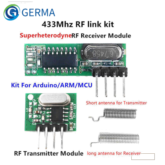
Application environment Remote control switch, receiver module, motorcycles, automobile anti-theft products, home security products, electric doors, shutter doors, windows, remote control socket, remote control LED, remote audio remote control electric doors, garage door remote control, remote control retractable doors, remote volume gate, pan doors, remote control door opener, door closing device control system, remote control curtains, alarm host, alarm, remote control motorcycle remote control electric cars, remote control MP3. Package Included: Receiver module (RX470-4) * 1pcs Transmitter module (WL102-341) * 1pcs Antenna * 2pcs (Short antenna for Transmitter; long antenna for Receiver.) Product Description [Receiver module ] Product Model: RX470-4 (RX470-4 is WL101-341 upgraded version, more stable performance, faster data transfer) RX470-4 superheterodyne wireless receiver module is receiving UHF ASK demodulators support ASK and OOK modulation. The receiver module has high sensitivity (-108dBm), Low-power performance, along with high dynamic range (greater than 60dB). Module uses highly integrated chip, built front-end low-noise amplifier,Mixers, filters, frequency synthesizer circuit, etc., can maximize the signal optimization.
0 notes
Text
1Set superheterodyne 433Mhz RF transmitter and receiver Module kit small size For Arduino uno Diy kits 433 mhz Remote controls
1Set superheterodyne 433Mhz RF transmitter and receiver Module kit small size For Arduino uno Diy kits 433 mhz Remote controls
Just For Today
Just For Today get free read 60 days !!!
Only At My Best Shop Place : https://s.click.aliexpress.com/e/_9woxOw
1Set superheterodyne 433Mhz RF transmitter and receiver Module kit small size For Arduino uno Diy kits 433 mhz Remote controls

$0.01 Application environment Remote control switch, receiver module, motorcycles, automobile anti-theft products, home security products, electric doors, shutter doors, windows, remote control socket, remote control LED, remote audio remote control electric doors, garage door remote control, remote control retractable doors, remote volume gate, pan doors, remote control door opener, door closing device control system, remote control curtains, alarm host, alarm, remote control motorcycle remote control electric cars, remote control MP3. Product Description [Receiver module ] Product Model: WL101-341 WL101-341 superheterodyne wireless receiver module is receiving UHF ASK demodulators support ASK and OOK modulation. The receiver module has high sensitivity (-110dBm), Low-power performance, along with high dynamic range (greater than 60dB). Module uses highly integrated chip, built front-end low-noise amplifier,Mixers, filters, frequency synthesizer circuit, etc., can maximize the signal optimization. Product Features 1.Support ASK / OOK modulation, the receiver sensitivity of -110dBm; 2.Operating frequency: 433.92 MHz, bandwidth of about ± 150KHz; 3.mains input voltage range: 3.0V-5V; Working current: Type :5.0mA (Requirement:VDD=5V) ; Type :6.0mA (Requirement:VDD=3V) 4. Quiescent Current: 1uA 5. Low power consumption; 6. good selectivity and spurious radiation suppression, and easy to pass CE / Fcc international certification; 7. Good local oscillator radiation suppression, multiple receiver module to work with (ie, more than single income) and will not interfere with each other, used together without affecting the receiving distance; 8. multiple transmission rates, the general module for 2KHz, up to 10KHz; 9. Temperature range: -40-85 °C 10. ultra-small size of 30.25 × 8.5 × 1 (mm) (can be customized according to customer) 11.External antenna: 32CM single core wire, wound into a spiral Circuit schematics
0 notes
Text
Introduction
Hi, my name is Steve, and welcome to Circuit Hack. In this blog I will be documenting my journey into the maker community, and DIY electronics.
I’ll be documenting everything I learn; from finding the best possible resources to aid learning, and join the community, to Ohm’s Law, and learning to solder, alongside starting out in C++ and Java programming.
The first projects I’m looking to make will be a solar panel, and battery system, and a simple irrigation system for a garden. After that, who knows?
For the first entry, following this short introduction I’ll be unboxing a brand new Arduino starter kit, and reviewing the product from the point of view of an absolute beginner (because that’s exactly what I am).

Then, I’ll be presenting some of the resources that you can use to help you start, and adding to this over time. Hopefully, I’ll end up with a good standard of materials and links to help new entrants to the growing culture of makers, and hackers around the world.
So, please join me on my journey into a new hobby, or learn along with me. Let’s build things!
1 note
·
View note