#calculatevoltagedrop
Explore tagged Tumblr posts
Visit Tumblr Blog
Explore Tumblr blogs with no restrictions, modern design and the best experience.
Last Seen Tumblr Blogs


Fun Fact
Women make up for the other 50% of Tumblr’s audience.
Text
How to Manage Rural Voltage Drop with the Right Cable Size
Long cable runs are required to supply power to remote areas, proportionally increasing resistance, which leads to voltage reductions at the load end. If left unaddressed, this can cause inefficient equipment operation, overheating, or premature failure, especially in high-demand or variable load conditions.
Knowing how to determine and calculate voltage drop helps maintain system reliability and comply with AS/NZS 3000 standards. Key variables such as load current, cable material, and environmental factors help calculate voltage drop accurately. This article unpacks the technical aspects of rural voltage management and offers guidance on choosing the right cable size to mitigate voltage loss effectively.
Why Voltage Drop Happens
Voltage drop refers to the natural consequence of cable resistance as electrical current travels through a conductor. Its effect becomes more prominent over long distances, which is commonly the case in rural environments.
Key causes of voltage drop include:
Conductor Resistance: All cables resist current flow to some degree. The higher the resistance, the greater the voltage loss.
Current Load: The more current flowing through the conductor, the more significant the voltage drop.
Cable Length: Voltage drop increases proportionally with the length of the cable run—a major concern for rural applications.
As per AS/NZS 3000:2018, voltage drop should not exceed 5% of the nominal voltage to stay within acceptable performance limits. Exceeding this can lead to dimming lights, reduced motor efficiency, and unreliable equipment operation. That’s why it’s important to calculate voltage drop accurately when sizing cables, especially for remote or large-scale installations that commonly functions with long cable runs.
Voltage Rise in Rural Solar Installations
In solar photovoltaic (PV) systems in rural areas, voltage rise is a major compliance issue. This refers to the voltage increase from the inverter output back to the point of supply, usually due to long AC cable runs with low loads.
According to AS/NZS 4777.1, the voltage rise between a grid-connected inverter and the main switchboard must not exceed 2%. Going beyond can cause inverter disconnection, export limiting, or system instability, especially in grid areas that have high voltage.
In order to avoid these issues, it's important to select larger cables or optimise system layout early in the design stage. Using a cable sizing calculator that considers voltage drop and rise can help ensure performance, safety, and full compliance with Australian standards.
Factors That Influence Rural Cable Sizing
Rural sites are subject to conditions that affect the cable size needed to control voltage drop. These considerations become even more important due to the increased likelihood of long cable runs, variable load profiles, and less predictable environmental conditions. There are several factors in choosing cables to consider, which include:
Current-carrying Capacity: In rural sites, where higher loads or long duty cycles are common (e.g. pumps, motors, welders), cables must be sized to manage the expected load continuously.
Voltage Drop: Although standards typically allow a maximum of 5% voltage drop, the cable size must factor in the length of the run and the load current to stay within acceptable limits, making it necessary to calculate voltage drop accurately.
Short-circuit Temperature Limit: Cables should also withstand the thermal energy produced during a short-circuit event until protective devices operate.
When choosing cables, ensure long-term reliability and maintain operational safety. A short cable can cause hazard, whilst a long cable may incur unnecessary costs. Thus, finding the right balance is important to ensure optimal performance that lasts.
How to Estimate Voltage Drop
Estimating voltage drop requires precise calculations that factor in current, cable resistance, and length. These become more important if they involve long distances or heavy-load environments. In manual calculations, the voltage loss formula is:
V = I · R
Where:
V = Voltage drop (in volts)
I = Current (in amperes)
R = Resistance (in ohms)
To put this formula in practical use, consider a 12V circuit powering a light 30 meters away. The cable has a resistance of 0.2 ohms per 100 meters (both directions total 60 meters of wire), and the light draws 5 amps of current.
Step 1: Find the total cable length
30m · 2 = 60m
The length of the cable (30m) is multiplied by 2 to account for the wire going from the power source to the load (light) and then coming back from the load to the source, completing the circuit.
Step 2: Calculate the total resistance of the cable:

The cable's resistance is 0.2 ohms per 100 meters. To scale it proportionally, it has to be multiplied by the total cable length, which gives 0.12 ohms.
Step 3: Use the Voltage Drop formula:
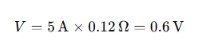
After calculating the total resistance, the voltage loss formula is used to calculate the voltage drop, which is 0.6V.
With this answer, you can also find the percentage of voltage using this formula:
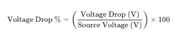
Which the calculation accounts for:
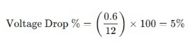
The source voltage refers to the light's 12V circuit. Thus, a 12V circuit with a cable with a resistance of 0.2 ohms per 100 meters and powering 5 amps of light has a voltage drop of 5%. This means an upsized cable, which, in this case, is unnecessary.
A straightforward approach such as this manual calculation can quickly get complicated when you're considering multiple variables. Hence, a modern cable calculator is used for fast, efficient, and compliant results.
Calculate Voltage Drop Easier with CableHero
In rural applications, voltage drop is a practical challenge that directly impacts system reliability, energy efficiency, and safety. Long distances, variable loads, and extreme environmental conditions make these installations vulnerable. Knowing how to determine voltage drop accounts for selecting the correct cable size that meets AS/NZS 3000 standards.
Whether you're an installer or project manager, having the right tool helps you with the calculations and compliance needed for high-performance rural electrical systems. Instead of relying on spreadsheets or trial-and-error, use CableHero’s modern calculator to streamline the process of accurately calculating voltage drop. To learn more, visit our website today!
0 notes
Text
Maintaining Australian Electrical Standards To Get The Optimum Electricity Output
Power transmission and supplying companies need to take care to provide the current in the most productive manner. This can be done by adhering to the Australian electrical standards which has laid down strict guidelines for the technicians and electricity equipment suppliers. These equipments are very much helpful in getting the optimum output from the wiring and cables, along with understanding the features in the transmission lines and use of different types of software. Wire transmission can be optimised if people calculate voltage drops in the circuit with help of these tools, so that the right size of cables, in the circuit is planned. These software tools are able to get the right and precise measurements of most of the components of the circuit along with the best results for transmission.· How does it benefit to calculate voltage drops and make other assessmentsThere are plenty of places where the electrical components are fitted and these are required to be in proper order. There will be the necessity of getting these components right to allow for optimum transmission through the wires and points. When the Australian electrical standards are maintained properly, there can be good features included in the power set up, with minimising of the power loss and wide range of software tools to calculate the loss of voltage.By keeping the current flow and voltage at optimum levels, the power transmission is quite good. This is an important feature of the circuits where people can calculate voltage drops new zealand and get the most appropriate figures to work with the right equipments and components. In this way, a number of circuits at different locations can be properly designed in the most appropriate manner.
0 notes