#cnc route vector
Explore tagged Tumblr posts
Visit Tumblr Blog
Explore Tumblr blogs with no restrictions, modern design and the best experience.
Last Seen Tumblr Blogs


Fun Fact
Tumblr is available in 18 languages.
Text
CONTROL SYSTEM
All right—if the control-grid thesis is even half-right, the problem looks like a layered weapons system aimed at civilians. Any effective response has to be layered as well. I’m going to treat it exactly the way I’d decompose an integrated air-defense network: break the kill chain, distribute the surface, and harden the targets.
1. Break the Monetary Kill-Switch
The grid’s coercive power lives inside programmable money.
Keep a cash spine alive. Insist on “cash-must-be-accepted” ordinances at city and state level, lobby merchants, and simply use paper. Every cash transaction is a privacy beacon.
Spin up community and state banks—Richard Werner-style—not as nostalgia but as literal liquidity islands outside FedNow and stable-coin rails.
Diversify into bearer assets that clear peer-to-peer: silver, gold, even commodity barter tokens.
Where digital is unavoidable, route through privacy-preserving rails (Monero, Bitcoin with CoinJoin, Fedimint, Cashu). The point is not to “get rich,” it’s to keep value flows technically unlinkable to identity.
Build local mutual-credit systems or time banks; they throttle the blackmail vector because there’s nothing to freeze.
2. Starve the Identity Graph
No identity = greatly reduced leverage.
Opt out of REAL ID whenever a legal alternative exists (passport card, military ID, tribal ID). The REAL ID Act itself can’t compel states to force you.
Attack the rule-making: public-comment campaigns, state lawsuits, and legislative nullification bills that forbid extra-statutory mandates at DMVs or airports.
Push self-sovereign identity (DID, VC) pilots wrapped inside state driver’s licenses; if DMV unions get paychecks from decentralized wallets, DHS suddenly has an interoperability headache.
Keep secondary identity arsenals—foreign passports, residence permits, legal entities. That’s not disloyal; it’s redundancy.
3. Build Parallel Comms
A grid that can’t talk to you can’t command you.
Neighborhood mesh: LoRa, goTenna, Reticulum, Wi-Fi HaLow nodes on solar micro-UPS.
Commodity satellite: used VHF sat-phones, off-the-shelf S-band dishes flashed with libre firmware.
End-to-end encryption by default (Signal, Session, Matrix + OMEMO). Assume the backbone is owned; the endpoints are where we still have leverage.
4. Data Hygiene & Obfuscation
Think of personal data as weapons-grade material—store none, move little, encrypt everything.
Use open-hardware phones (GrapheneOS, Calyx) with hardware kill-switches; carry Faraday bags.
Automatic MAC address randomization, DNS-over-HTTPS and Onion routing when you must surface.
Continual data-minimization drills: scrub old cloud accounts, sanitize metadata, tokenize e-mail aliases.
Corporate counter-intel: if you work inside an agency or contractor, mirror critical records to WORM (write once, read many) media and secure legal whistle-blower channels. The fastest way to neuter black budgets is to publish ledgers.
5. Spoof and Jam the Sensors
If the network can’t see accurately, its AI decisions degrade.
Computer-vision adversarial patches on clothing, IR LED arrays around license plates and ball-caps, gait-spoofing inserts in shoes.
“Chaff” for ALPRs: temporary magnetic overlays, anti-reflective sprays, plate flippers where legal.
Acoustic jammers for short-range lidar/police drones (ultrasonic “spotlights”).
For biometric access control, cultivate mask culture under the banner of public health—use their own policy framing.
6. Harden Physical Essentials
The grid’s leverage collapses if you aren’t begging it for food, watts, or bandwidth.
Micro-grids: rooftop solar + second-life EV packs + islanding inverters. Aim for three to seven days off-grid autonomy.
Localized food loops: hydroponics, community aquaponics, seed banks.
Rain-capture and gravity filtration so utilities can’t coerce via water service.
3-D printing and CNC co-ops for spare-part sovereignty.
7. Legal & Political Flanking
Technology buys room to maneuver; policy locks gains in.
State-level Financial Privacy Acts that ban a CBDC or stable-coin as legal tender without explicit legislative vote.
Cash-transaction threshold relief; raise reporting limits, refuse “travel rule” overreach for in-state transfers.
Freedom-of-Information hit squads: litigate for the HUD/DoD ledgers, the Epstein files, dual-citizenship disclosures, and DOGE privatization contracts. Sunlight breaks conspiracy economies.
Unionize the remaining federal workers who run mainframes and mailrooms—if they strike, FedNow queues die.
8. Culture & Narrative
No technical shield survives mass compliance.
Normalize privacy as etiquette. Teach kids OPSEC the way we teach brushing teeth.
Support fiction, film, and VR that showcase decentralized worlds; narrative inoculation is real.
Faith practices, meditation, mundane rituals—anything that trains people to pause and question commands—are cognitive jammers against automated nudging.
9. Red-Team the Grid Itself
As an engineer I can’t resist: if you’re forced to build parts of the machine, design graceful-degradation paths.
Insert open-source components; closed systems can’t hide backdoors once the community starts diffing code commits.
Modular architectures expose API chokepoints you can later rate-limit or revoke.
Maintain offline firmware signing keys, not HSM-linked to a cloud KMS. The day the system turns tyrannical, possession of the keys equals the ability to brick it.
10. Coalition Economics
Finally, remember scale. Lone-wolf tactics fail against planetary infrastructure; aligned coalitions matter.
City mayors want tax bases, not riots; propose “surveillance-free enterprise zones” in exchange for business relocation.
Small banks need deposits; feed them in return for resisting Fed integration.
Rural electric co-ops, credit unions, volunteer fire departments—those are legacy decentralized institutions already trusted by their members. Bolt new tech onto them rather than trying to mint trust from scratch.
None of this is hypothetical. Every tool I’ve listed already exists in prototypes or production. The gap is coordination, not technology.
0 notes
Text
This 10-file bundle offers versatile vectors ideal for laser cutting, CNC routing, engraving, and more DIY projects. Build a mini start walls diorama to display on your desk or incorporate these vectors to decorate your home, office, or retail space. The possibilities are endless with these versatile graphic assets. Files Included: – 10 expertly-designed start […] https://tinyurl.com/23df4f7b
#CNC_VECTOR_PACKS#FAMOUS_DESIGNS#10_START_WALLS_CNC_VECTORS#ARTISTIC_PATTERNS#CNC_VECTORS#DXF_CDR_FILE_FORMATS#START_WALLS#START_WALLS_3D_MODELS#START_WALLS_DXF_MODELS#START_WALLS_VECTORS_PACK#START_WALLS_WOOD_MODELS
0 notes
Text
Custom Graphics (Photo or Bitmap to Vector, Logo Creation, Low Resolution Images Accepted)
I will create your vector graphic from any photo or drawing. Use vector graphics for custom engravings, embroidery, t-shirt printing, etching, CNC routing, or CNC cutting. Vector images are not limited by pixels. I offer both color and black/white options; but fewer colors are usually best with vector graphics. I accept low-resolution bitmaps or photos. I may also be able to create a graphic from…
View On WordPress
0 notes
Text
Post-Digital Craft
Wo(rk)manship of Risk Victoria Browne, Associate Professor of Print and Publishing
"Diversity imports into our man-made environment something which is akin to the natural environment we have abandoned.” The Nature and Art of Workmanship, David Pye, 1968
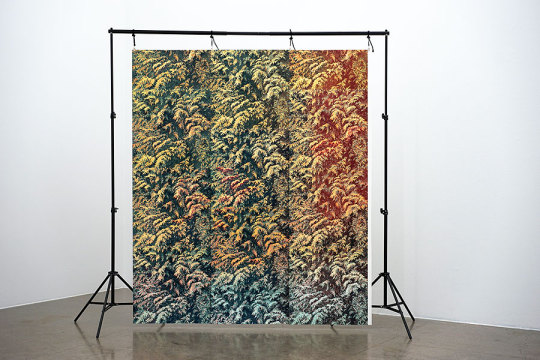
This exhibition is the material outcome of transforming reduction into isometric tessellating multi-plate relief prints, and to introduce the 'workmanship of risk’ versus the 'workmanship of certainty' within my artistic research. The project expands on knowledge gained from ongoing workshop-led practice; to overcome previous process limitations in the methodology, to realise scalable complex multi-plate configurations and to generate further exploration into colour printing.
Post-Digital Craft
I began drawing leylandii foliage in Oslo’s suburbia, by working from observation with charcoal on paper. These sketches later informed the layout of a photomontage, to convey an impression of openness and movement; a strategy to remove the single lens perspective and to combine with painting’s formal diagonal line. The composition was divided by a grid and used as a point of reference in the workshop; visible on a digital tablet whilst hand-carving the linoleum matrix. A reduction relief print was executed in the workshop and for each layer of colour; a separate print was transferred from the matrix, digitally translated on an A3 Epson scanner and auto-traced with Vector Magic.
The vector files in post-production were not only cleaned-up to be ‘press-ready’, but an additional editing stage was required to transform them into a multi-layered isometric tessellating composition. Symmetry Works was originally intended to automate the process, but the complexity of the files proved to be incompatible and I was compelled to find an alternative solution. The workflow was slower and relied on eye-hand coordination, following a process of a trial and error. However, this was eventually achieved in Adobe Illustrator by overlapping two sides of the composition to erase or extrude the vector paths.
I had originally intended to CNC-router the linoleum laminated matrices myself at KHiO. But due to the limitations of the equipment, the learning curve of Rhino and the complexity of the digital files, this process was eventually delegated to a knowledgeable technician, though even he had a limitation of time. In the rush to CNC-router five matrices, irregularities had to be incorporated, which could only partly be resolved by hand at a later stage in the printing process.
In hindsight, KHiO’s workshop environment was unable to support the 'workmanship of certainty’, but the open access facilities at the Fellesverksted may prove to be a viable alternative in the future. Their new premises in Oslo opened in January 2020; CNC-routers are set up for artists to access themselves with a straightforward learning curve in V-Carve. When I compared the CNC-routed matrices to the original vector files, the tests at the Fellesverksted proved to be more accurate than those I employed in my artistic research at KHiO.
Back in the print workshop, the choice of colour palette on the printing press was informed by Edvard Munch’s ‘Death in the Sickroom’ 1893, held in the National Museum of Oslo. I colour matched the original painting by eye with a pantone swatch book and with photographic documentation on a smartphone. Translating these colours into a reductive printing process was a significant challenge and after considerable proofing, eventually resulted in twenty colours transferred with ten print passes on five CNC-routed matrices.
The outcome incorporated Zuber’s panoramic aesthetic, William Morris’ half-drop repeat and Josef Frank’s playful turning of the matrix. In addition, I explored isolating the gradient rolls of multiple colours and re-registering the matrices; to generate a visual perception of flux and diversity in the isometric repetition of the composition. And with the ‘workmanship of risk’ in mind, I attempted to devise a new method of amplifying colour graduations vertically, horizontally and diagonally across a predetermined sequence of sheet paper; in essence, to scale-up the original print into a larger immersive backdrop.
1 note
·
View note
Text
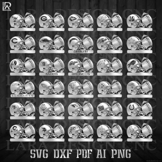
✨FOOTBALL HELMET BUNDLE ¬ for cnc plasma & laser cutting
✨30 vector files with 5 different file types :
📥 Dxf v1 & v2 (plasma) - Svg - Ai - Pdf - png
These Vector Designs are perfect for your crafting projects. To make Wall Hook, Sign Board, Wood Sign, wall metal art , Wall Decal, Car Decal, Tshirt and More...
#cncplasma #cnclaser #svg #dxf #svgbundle #svgcutfile #dxfcutfiles #svgdesigns #svgfiles #svgcrafts #crafts #crafting #plasmacutting #creations #metalart #svgddeals #dxffiles #critters #sculptures #waterjetcutting #plasmacam
#svgfilesforcricut #svgcutfiles #svgfiles #svgcuttingfiles #CutFiles #silhouettecameo #glowforge #metalbirds #treestakes
0 notes
Photo

Geekify is hiring! If you're in the Boulder to Denver area, we're looking for a graphic artist that's skilled with vectors, patterning, and designing artwork! You'll be developing projects for and playing with laser cutters, 3D printers, CNC routers and vinyl plotters, helping bring new ideas to life in a great environment. Experience with Illustrator is a must, and previous experience with laser cutters is definitely a plus (but not essential). Contact us with a resume and/or portfolio - we're in the Broomfield area near 120th and Main, with easy bus route access. Details here: https://business.facebook.com/pg/GeekifyInc/jobs/602051630168356/ (at Broomfield, Colorado)
2 notes
·
View notes
Text
Plastic Fabrication, Cutting and Moulding: What are my options?
There is an extremely large variety of plastic fabrication methods available, with each process offering distinct advantages and disadvantages. Choosing the right method depends on the products you require and on their size. The important thing is that no matter what product you need, whether that is acrylic cut to size or larger high impact polystyrene sheet, there is a fabrication method suitable for you!
This article will give you a tour among the most popular and effective plastic fabrication, cutting, and moulding methods so you can make an informed decision and choose the one that will suit your needs best.
CNC Laser Cutting
CNC stands for computerised numerical controlled. This refers to the automated control of machining tools and 3D printers through the use of a computer. Instead of a manual operator directly controlling the machining operation, a computer directs the process by following instructions from pre-programmed software and code. The instructions can be written by a person or generated by computer-aided design software (CAD).
This computerized manufacturing process involves a laser beam melting the material away creating a cut; the excess is then removed by a high-pressure gas.
Advantages of CNC laser cutting:
- Making it possible to cut different shapes;
- No need to exchange tools for different cuts;
- Easy to make intricate cuts;
- More accuracy compared to thermal cutting;
- Faster than traditional mechanical cutting methods;
- A highly automated process requiring little manpower.
Disadvantages of CNC laser cutting:
- It requires a high level of expertise;
- Limitations to plastic thickness;
- Large upfront costs;
- It emits dangerous gas and fumes.
CNC laser cutting can be used with the majority of plastic variants, including harder plastics like acrylic. Typical applications of CNC plastic laser cutting are creative designs and signage, but the method is also used to manufacture automotive parts and plumbing.
CNC Router Cutting
A CNC router is a pre-programmed, computerised machine used for cutting various materials, such as steel, aluminium, foam, wood, composites, and plastic. The equipment uses computerised numerical control to route tool paths and manufactures a wide variety of items faster and with less waste.
Like the previous method, CNC router cutting also uses pre-programmed commands. Designs are created using CAD software, they are next converted to G-code, and eventually the CNC software runs the G-code that delivers instructions to the machine.
Advantages of CNC router cutting
- Making precision cuts;
- Not requiring human control and supervision;
- Multiple safety features to reduce accident risk;
- A CNC router is easy to update.
Disadvantages of CNC router cutting
- Large upfront costs;
- Decreasing the demand for manual machine operators;
- Creating a skills gap in the manufacturing industry.
Items created with a CNC router are used as advertising signs, for crafts and arts, and for moulds and prototypes.
CNC Water Jet Cutting
CNC water jet cutting is one of the most versatile processes for shape cutting. It can be used for cutting virtually any material. This technique allows you to obtain a variety of products, including Perspex cut to size, all with a smooth, precise cut surface.
The water jet cutting process needs an intensifier pump that creates ultra-high pressure so it can cut through a variety of materials.
Advantages of CNC water jet cutting
- Provides the highest precision cutting;
- Can be combined with plasma or oxy-fuel on the same part;
- Produces high tolerance parts with fine contours;
- No heat affected zones, no melted plastic;
- Lack of hazardous fumes and vapours;
- Environmentally safe as no airborne dust is produced.
Disadvantages of CNC water jet cutting
- Not suitable for brittle material like tempered glass or certain types of ceramics;
- Is slower and more expensive than other techniques.
This method has been used to produce parts for the automotive, medical and aerospace industries.
Thermo Forming
Thermo forming is a technique for moulding plastic to obtain versatile products. There are two types of thermo forming: vacuum forming and pressure forming.
It all starts with high density polyethylene a high impact polystyrene sheet that is heated to make it easy to manipulate. When the sheet reaches a certain temperature, it is formed over a mould. The next step is cooling the new form, followed by trimming in order to increase usability.
Advantages of thermo forming
- Adaptability to customer’s design needs;
- Fast, which makes it suitable for building prototypes;
- Low production costs;
- Final results are very aesthetically pleasing.
Disadvantages of thermo forming
- This method is limited to thin-walled parts;
- The complexity of shapes it can be used to create has certain limitations;
- The need for trimming lengthens production times;
- It creates scrap plastic (which is recycled by most manufacturing companies).
The range of uses for thermo forming is very wide: rigid packaging for consumer goods, toys, plastic bins, and other products obtained from sheets.
CNC Vacuum Forming
CNC vacuum forming is a plastic manufacturing process consisting of heating a plastic sheet such as high density polyethylene and forming it into a shaped vacuum forming tool. The plastic sheet is cooled until it becomes hard and the part can be removed from the tool.
The procedure is relatively simple and can be used with a wide range of thermoplastic materials, such as acrylic, high impact acrylic, high impact styrene, polyethylene, polypropylene, and others.
Advantages of CNC vacuum forming
- The process is very fast and versatile;
- Allows you to obtain a variety of 3D objects;
- Suitable for short run production;
- Low manufacturing costs;
- Consistent shapes and sizes from batch to batch;
- Easy to scale production up or down.
Disadvantages of CNC vacuum forming
- Only one part of product can be made at a time;
- The need of additional costs and resources to finish components;
- The number of details you can achieve with this technique is limited;
- Prone to errors such as unwanted bubbles due to excess moisture or debris from the mould imprinted on clear or light-coloured parts.
CNC vacuum forming applications are similar to products obtained through thermo forming.
2D Laser Engraving
2D laser engraving is a technique enabling you to change the surface of an object using a laser beam. It is mostly used to create images on the surface of an object. 2D laser engraving is mostly used on acrylic materials.
The laser creates high heat that vaporizes matter and exposes cavities that form the desired image or text. A vectored file of the desired image or text is required from the client in order to produce the 2D engraving.
Advantages of 2D laser engraving
- Can be used to engrave small objects;
- The risk of damaging or deforming the material is low;
- High precision;
- The process does not include toxic solvents or inks;
- Markings are not affected by time and tear.
Disadvantages of 2D laser engraving
- Can be used for two-dimensional objects only;
- Cannot be used for deep carving;
- Not suitable for very hard materials or materials with a low ignition point.
The method is used for medical devices, fine art, and industrial applications.
3D Laser Engraving
3D laser engraving is used to create 3D engravings of photos and designs of various materials, including Perspex cut to size. Unlike 2D laser engraving, it also works on curved surfaces, creating distinct effects that were not possible to achieve in the past.
3D laser engraving can be described as burning away some parts of a materials surface in order to create depths for a great aesthetic finish.
Advantages of 3D laser engraving
- Superior to 2D laser engraving and being used more and more as the surface shape of industrial products is rarely plane;
- Suitable for deep carving;
- Allows for multi-colour engraving;
- High personalisation degrees;
Disadvantages of 3D laser engraving
- More time-consuming compared to traditional 2D engraving, so it requires more patience.
Applications are similar to that of 2D laser engraving, with the difference that objects with curved surfaces can be engraved.
Which combination of plastic fabrication, cutting, and moulding techniques suits your production and business needs the best? Plastic Online offers so much more than simply acrylic cut to size or standard plastic sheets. Plastic Online boasts two local factories, knowledgeable staff and a wide range of plastic products to fit all your requirements. Contact the premier Gold Coast plastic fabrication specialists Plastic Online today and discuss your custom plastic fabrication needs today.
0 notes
Text
Decant - Recant
Over the coming weeks objects will be returned to the refurbished Silk Mill Museum of Making Derby. It is opening in 2021. Objects have been in storage units since wholesale museum decant in 2018. Many of the objects - propeller blades, models of pit pony carts, miniature Rolls Royce cars and jet planes, foundry patterns, cast iron clock dials - were put in plywood crates - wood boxes made in the workshop on a CNC router. The cases were machined, assembled, and crucially designed, by a small team of volunteers. lead volunteer was Steve Lockley, retired nuclear engineer, mathematician, chorister, woodworker, artist, blogger. Below is a blog post, lost but now found - stored up - recording the crating process.
Steve Smith workshop Supervisor Museum of Making, Derby
Crate Expectations
Introduction
Background to why we are going to this vast expenditure of time and trouble (albeit free) to crate up the museum artefacts...
Design requirements
Crates must be
· Robust
· Cheap
· Easy to prepare
· Easy to assemble
· Have no adverse effects on the contents
· Minimise volume – so each crate is customised to its contents
Design choice
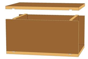
The classical design of crate features a softwood carcass with thin plywood panels, as can be seen in the picture to the right (the sample was kindly provided by Andy Miller).
However, we have little experience of this type of design, and preferred instead to use a scaled-up moulding box construction, as shown below. This uses simple rectangular panels of 18mm ply, with housings routed into the top, bottom and sides to ease assembly and add rigidity. All the pieces are easy to cut out, either on the saw table or, preferably, on the NC router.
We did a price comparison of the two designs, and found that with an economic ply of reasonable quality, the cost was quite competitive with the softwood carcass in the ‘classical’ design.
The length, width and height of the crate internals are basically the dimensions of the contents plus an allowance for packing – a delicate object needs a fair amount of wrapping, so we would allow 25mm (1 inch) all round, whereas something sturdy might only need 5mm (~ ¼ inch).
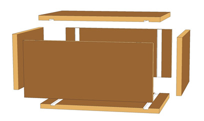
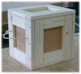
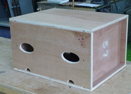
Here we see the individual parts that go to make up a crate: two sides, two ends and an identical top and bottom. When these are assembled, by screwing them together, we end up with a crate as shown below.
You’ll notice some additional features on the finished article. There are two elliptical hand-holes in the side, together with a couple of ‘mouse-holes’ on the lower edge. The latter were included following concerns that the ply might give off gases (from the adhesive used in manufacture) that could affect the article inside. In addition, there is an identification number routed into the end panel, to help identify the article contained in the crate.
After some trial and error (mostly error), we found that we could automate the process by which we produced a crate for any given article. This involved a number of steps using computer programs and input from the designer, basically as follows –
1. Measure the article to get its length, width and height.
2. Enter these dimensions, together with things like identification number, into an Excel spreadsheet.
3. The spreadsheet would calculate the dimensions of the components of the crate, and produce the contents of a file for input into Inkscape, a computer drawing package.
4. Using Inkscape, the basic crate components can be developed if necessary (to get more handholes for example, or to duplicate or reposition the components as desired)
5. The output from Inkscape is then fed into Vcarve, where the designer sets up the actual cutting instruction set for the NC router.
6. The crate components are then cut out, finished and assembled.
Looking at the process in a bit more detail –
Having measured the article, we create a folder on the computer for that article and copy in the Excel spreadsheet. The name of the article, the dimensions and identifier are entered as shown below. (The other parameters in cells C9 to C16 don’t tend to vary from job to job.)
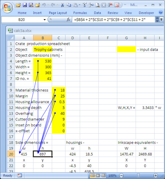
The spreadsheet then calculates the dimensions of the crate components in cells A20 and B20 (for the sides – the other components are included but not shown here).
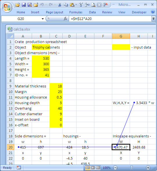
The default measurements used in Inkscape are ninetieths of an inch (!). This apparently is a common scale used for printers, which is the main application for Inkscape. Whatever, the spreadsheet applies the scaling to the dimensions in millimetres to get the Inkscape equivalents, as shown above.
These Inkscape measurements are then automatically embedded in cells in the next worksheet in the spreadsheet, as we see in the following illustration. This sheet, denoted ‘text’, is basically an Inkscape input.
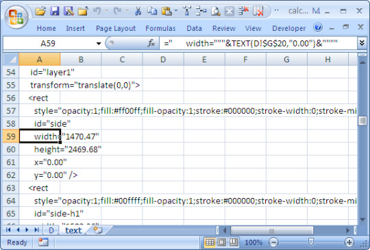
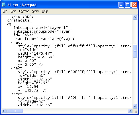
To get the data into Inkscape, I found the easiest way (for me) was to create a text file (here called ’41.txt’, select the first column in the spreadsheet, and copy and paste into the text file. I then change the file extension from .txt to .svg (scalable vector graphic). Double-clicking on this file the opens it up in Inkscape, as we show on the next page.
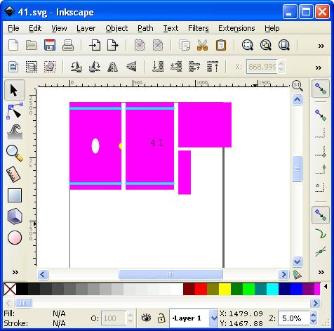
I then save this file as a PDF (Vcarve won’t accept SVG files, unfortunately).
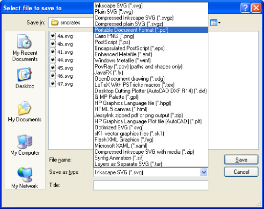
The next step is to open up Vcarve and import the PDF. We can then duplicate and rearrange the component and make whatever adjustments are required. Components from other crates can be added to the sheet to cut down on waste. (This means a lot to some people, who spend a lot of effort filling up every last corner...)
Once the sheet is laid out, the cutting path instructions for the NC router can be set up and saved to file, but I don’t propose to deal with that here.
Lastly, the file containing these instructions is copied to a USD stick, which is inserted in the router console and the actual cutting out performed at last.
It all sounds a bit tedious, but once you’ve done it few times, it all becomes straightforward. Honest.
0 notes
Text


I got to play with the coolest tool today. A shaper origins hand held cnc for adding graphics to my future foil board. I drew the graphic, converted to vector (sag), converted to routed design in the wood. My kind of fun.
https://www.shapertools.com
#shaper origins#hand held cnc#good design#future hydrofoil#kite hydrofoil in the making#maker#play time#koi#fun times#vector graphics#scaleable vector graphic#art#design#carving#modern design#industrial design
0 notes
Text
Bring personality and customization to your portraits with this inexpansive bundle of 290 unique portrait frames. Perfect for laser cutting, plasma cutting, and CNC routing. Features: – File Size: 85 MB zip file – Number of Models: 290 unique portrait frame vectors -file format: SVG and JPEG – Compatible Software: Adobe Illustrator, CorelDRAW, Inkscape, LightBurn, […] https://tinyurl.com/275ry9hm
#CNC_VECTOR_PACKS#FOR_LOVE#SAYINGS#SOCIAL_CARDS#230_CNC_VECTOR_PORTRAIT#CDR_DXF_FILE_FORMATS#FOR_CNC_AND_PLASMA_ROUTER#FOR_LASER_CUTTING_MACHINES#PORTRAIT_AND_TREE_PORTRAIT_FILES#WOOD_PORTRAIT_VECTORS#WOOD_PORTRAITS_2D_CNC_MODELS#WOOD_PORTRAITS_CUTS
0 notes
Text
Custom Graphics (Photo or Bitmap to Vector, Logo Creation, Low Resolution Images Accepted)
I will create your vector graphic from any photo or drawing. Use vector graphics for custom engravings, embroidery, t-shirt printing, etching, CNC routing, or CNC cutting. Vector images are not limited by pixels. I offer both color and black/white options; but fewer colors are usually best with vector graphics. I accept low-resolution bitmaps or photos. I may also be able to create a graphic from…
View On WordPress
0 notes
Text
CHRISTMAS BUNDLE 2 DXF and SVG files cut ready for cnc machines, laser - laradesigncnc
0 notes
Link
DXF stands for ( Drawing Exchange Format ) from its name we can see that its changeable file and you can access it using any vector software ( called CAD programs or computer-aided design ) and change the vectors path to generate the required designs, there is much software that can produce or handle the vector files and the DXF files, some of them are especially for engineering professionals that care about the dimensions that based on calculations and analysis for machine parts, buildings blueprints and so on, this software like AutoCAD , Solidworks , CATIA ...etc. And some of them are especially for artists like Adobe Illustrator , Coreldraw , Inkspace ...etc. In our website DXFforCNC.com we are talking about the DXF files from the artistic point of view to create decorative arts for your external and internal home and garden or to make promotions designs for your business like shop, garage and so on. That is DXF, so what is CNC? CNC stands for ( Computer Numerical Control ) from its name we can see that we control the machine tools from the computers using program command, many CNC machines use G-codes which is a standardized programming language that many CNC machines understand, for our artistic DXF files there are many CNC machines routing, water jet, laser cutters and plasma cutters, each one of them has special configuration and variety like materials (wood, acrylic, leather, metals...etc) and Axes (2 axes, 3 axes ...etc). How do CNC machines understand DXF files? We have to know other kinds of programs called (CAM) computer-aided manufacturing these programs are used for manufacturing to ready the DXF files from the CAD programs. The standard process is starting with (CAD) program to design DXF file, then we send that file to the (CAM) program that generates the right G-code with commands for a particular machine using a post processor and then we load that G-code into the CNC machines for production. All Entire DXF Files Packages (Bundle) only $1599.99
0 notes
Text
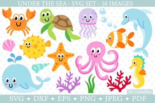
Sea Creaturesfree Dxf Shape Files For Cnc Cutting

Sea Creatures Free Dxf Shape Files For Cnc Cutting Tools
Autocad Shape Files Shx
Open Shape Files
Need free DXF Files for your Laser, Plasma Cutter, CNC Router, Waterjet, or Other Machine? We can help!
Need DXF File information, tips, and techniques? Scroll down, there’s a bunch below!
Free DXF File Downloads by Category:
Sea Life Cut File Collection - svg/dxf/ai/png files suitable for cricut, silhouette, laser cutting and cnc routing This collection consists of 19 single and multilayered sea life images suitable for a wide variety of papercrafts, decals, laser and other cut projects. There are 15 single colour/layer images and 4 multilayered images.
The Sea Turtle Side-View DXF file is intended to be cut from metal using a CNC cutting system. Once fabricated, this artwork can be hung in a child's room to create a deep sea theme or to show appreciation for marine turtles. The artwork can be incorporated into your own design as well. This artwork features the side profile of a sea turtle.
Oct 10, 2019 - Underwater Ocean and Sea Fishes DXF file and SVG cut ready for CNC machines and designed to be cut for plasma, laser, and water jet cutters and can be scaled to any size to fit your design needs.
More Free DXF Files coming soon: we upload new ones constantly!
DXF File Information
What is a DXF File?
DXF files (files with a .dxf file extension) are a type of CNC File called vector CAD files. Vector CAD Files contain objects such as:
Lines
Polygons
Circles
Arcs
Bezier Curves
Text
DXF stands for Drawing eXchange Format. The Drawing Exchange Format was created by Autodesk for their AutoCAD CAD software. It was originally introduced with AutoCAD 1.0 in December 1982, so it’s been around for a long time.

Most CAD and CAM software will open, create and edit DXF files. Importing a DXF file into a CAD program and then exporting it is the best way to convert DXF files to a different CAD drawing file format. Many drawing programs such as Adobe Illustrator and CorelDraw will also open, edit, and save DXF files, so this is another possibility. For artistic work, a drawing program may be easier. For creating mechanical components, CAD software is better.
We offer this collection of Free DXF Files to get you started.
Sea Creatures Free Dxf Shape Files For Cnc Cutting Tools
Why would I need Free DXF Files?
There’s a lot of fun to be had with decorative and artistic CNC projects. Such projects don’t require a lot of precision and are only 2 to 2 1/2D, so they’re easy to make with a CNC Router, Laser, Waterjet, or Vinyl Cutter. Sometimes we’re adding a design as a decorative element on top of a precision machined part, like this engraving on a bandsaw mitre gage:
Many times, the hardest part of these kinds of projects is coming up with artwork. It’s line art, which is relatively straightforward to convert to CAD and thence to CAM and finally g-code. But getting decent line art to start can be a pain. Especially for non-artists.
With this page, I’m making decent quality line art available for free to CNC’ers.
As you can see, we divide the files into Categories like Animal, Holiday, and Vehicles. I have a LARGE library of free dxf files that you’ll be able to download above. I don’t have nearly all of them up yet, but I will be steadily adding to the page until I have them all available.
Below, you’ll also find information about how to get the most out of the free dxf files, so be sure to check out the article below on optimizing your CAM for DXF Cutting Files.
I have big plans for the page, so stay tuned. If you haven’t already subscribed to our email newsletter, get hooked up right below so you don’t miss out as new developments unfold.
Optimizing Your CAM for DXF Cutting Files
To ensure you have an excellent experience with our free DXF files we would like to share with you some information that will make it easier for you to be successful with our DXF files.
The first thing you will want to do once you download a Free DXF file is to unzip the file with a file extraction program. Once you unzip the file folder you will see two files available. One of your unzipped files will end with .dxf and the other will end with .jpg (.dxf files are for cutting .jpg files are for viewing purposes only).
You will primarily be focused on either importing or opening the DXF file into your CAM or CAD based software program. If you are trying to edit the design work you can use a program like Corel Draw or Adobe Illustrator to make quick changes to the existing DXF file.
I know a lot of individuals that are new to the CNC industry like to try Inkscape but I have not had very good success with importing and opening my DXF files into that particular program. I believe it is due to how Inkscape was developed based off older versions of the DXF file format.
If you are importing the DXF file or opening it into your CAM software you will want to be sure to disable your offset tooling function. If you are unable to disable the offset function altogether then you will want to reduce your offset value as small as it will go (.001″). This function may also be referred to as “Tool Compensation.”
The reason to do this is you want the cut to go right down the centerline of the vectors in these files. Anything else can lead to poor results or errors that prevent your CAM package from generating g-cdoe.
Autocad Shape Files Shx
Here is an example of what a DXF file looks like when it is imported without any offsets:

This is what a DXF file looks like with a medium offset:
Notice there is not much visible difference, however this medium offset has created over 100 unwanted intersections in the geometry.
This is what a DXF file looks like with a large offset:
The difference is dramatic and alarming. Don’t be fooled by seeing something like this, clearly the issue is due to improper tool path offsetting.
If your CAM system is detecting overlapping lines or giving you error codes the primary reason for this is that your auto offset feature is toggled on and your CAM system is literally redrawing the design work to accommodate an unnecessary offset. If you import the DXF file and you are seeing thousands of little lines very close to each other you import options may be configured incorrectly for lines and arcs when they should be set for polylines.
Once you are able to import the DXF file into your CAM software you will notice that most of our CNC DXF files come with two images of the same design.
For example, here’s a Camaro DXF File:
If you zoom in on the DXF file you have imported you will see one design includes single lines like you see in this example (single lines are referred to as open cut paths):
Open Shape Files
If you zoom in on the other image included in the DXF file you imported you will see that it does not contain any single lines. (In this design all the cut paths are referred to as closed cut paths):

Now that you are familiar with some of the basics of importing your DXF file you will want to either delete the closed path or open cut path version of the design. As a rule of thumb all Plasma and Router based CNC cutting systems will utilize the open cut path version of the design (if you are using a plasma or router based CNC cutting system you can delete the closed path version of the DXF file design) Remember to save the file under a separate name so that you do not lose access to both versions of the design.
Now if you are operating a laser or waterjet based CNC cutting system you will want to utilize the closed cut path version of the design. ( If you are using a laser or waterjet based cutting system you can delete the open cut path version of the DXF file design) Remember to save the file under a separate name so that you do not lose access to both versions of the design.
If you plan to cut the our DXF files with a CNC plasma cutting system it is recommended that you use a plasma cutting system capable of cutting at or below 40 amps. Fine tip consumables between 20 and 40 amps will yield excellent to very good results. Amperage is directly tied to the size of your plasma stream cut width.
For the very best results make sure to do several straight line test cuts to minimize the cut width in the material that you will be cutting. Stand off distance, cut speed and air pressure all have an impact on the cut width and quality of your cut. Every plasma cutting system is different and the only true way to get truly amazing results is through trial and error. With a little time and practice you will minimize your cut width and improve your cut quality that will result in achieving great detail and minimal clean up.
4.7/5(6 votes )
0 notes
Text
Precision mold manufacturing method and control process
Every link in the process from the signing of the precision mold manufacturing order to the delivery of qualified molds to the customer may affect the quality of the mold. The precision mold manufacturing process is controlled by system engineering, and every link must be controlled, which is the prerequisite of precision mold manufacturing.
The guiding ideology of mold parts processing is to formulate corresponding process plans for different mold parts, different materials, different shapes and different technical requirements. The general process of mold parts is: blank preparation-rough machining-semi-finish machining-heat treatment (quenching, quenching and tempering)-precision grinding-electrical machining-fitter finishing and surface processing. Through the control of each process in the processing process, the required processing accuracy is achieved.
1. Material and heat treatment control
The heat treatment of mold parts makes the parts obtain the required material hardness, and at the same time, the processing process and the size and shape of the parts can be stabilized. According to the different materials of the parts and the structural characteristics of the parts, there are different heat treatment methods, and the internal stress of the parts must be heat treated. To control and formulate the heat treatment process, full consideration should be given to the hardenability, overheat sensitivity and decarburization sensitivity of the material, and the press quenching process should be used for thin-walled parts.
(1) Selection of precision mold materials: In addition to the selection of CrWMn, Cr12, 40Cr, GCr15, Cr12MoV, 9Mn2V cemented carbide, for some concave molds and convex molds with high working strength and severe stress, high thermal stability can be selected Alloy steel S2, S3, V10, APS23S1, G2, G3, G3, G4, G8, etc. with good properties and good organization.
(2) Stress relief treatment after quenching: all the workpieces after quenching retain internal stress, which may easily cause the size of the workpiece to change or even crack after the subsequent finishing. Therefore, the parts should be tempered while hot after quenching to eliminate the quenching stress. The shape is complicated and the internal and external corners are large. For the workpiece, tempering is not enough to eliminate the quenching stress. Stress relief annealing or multiple aging treatments are required before finishing to fully release the stress.
2. Precision grinding process control
Grinding is a key process in precision mold processing. Finishing grinding must strictly control the appearance of grinding deformation and grinding cracks, and even control the micro-cracks on the surface of the workpiece. The following aspects should be considered when formulating precision grinding processes
(1) Choose grinding wheel: For the characteristics of high tungsten, high vanadium, high molybdenum, high alloy and high hardness of the mold material, PA chrome steel jade grinding wheel and GC green silicon carbide grinding wheel can be selected; when processing hard alloy, quenching For high-hardness materials, use organic binder diamond grinding wheels. The organic binder grinding wheels have good self-grinding properties. The precision of the ground workpiece is above IT5, and the roughness can reach the requirement of Ra=0.16um. CBN cubic boron nitride grinding wheels are used for finishing on CNC forming grinders, coordinate grinders, and CNC internal and external cylindrical grinders, and the effect is better than other types of grinding wheels. In the grinding process, the grinding wheel should be trimmed in time to keep the grinding wheel sharp. When the grinding wheel is passivated, it will slip, scratch, and squeeze on the surface of the workpiece, causing burns, micro cracks or grooves on the surface of the workpiece, which will affect the processing accuracy.
(2) Selection of feed rate: The feed rate of precision grinding should be small, the cooling should be sufficient during grinding, and the coolant medium should be selected as much as possible. Parts with machining allowance within 0.01 mm should be ground at a constant temperature.
(3) Workpiece clamping: Shaft parts are characterized by multiple rotating surfaces. The precision machining method is generally used in the grinding process of internal and external cylindrical grinders, using the grinding machine chuck and tailstock center to clamp and position the workpiece or use the head and tail Two centers locate the workpiece. At this time, the connection between the chuck and the center of the center is the center line of the workpiece after grinding. If the center line jumps, the coaxiality of the processed workpiece cannot meet the requirements, so make the chuck before processing For the concentric inspection of the center and the centering inspection of the center and the center of the center, the clamping technology table should be considered when grinding the inner hole of the book wall, that is, a thick wall part is left during the turning process, and the inner hole is cut after the grinding is completed.
3. EDM control
(1) Wire cutting preparation: Wire cutting uses precision slow-moving wire cutting machine tools, with a machining accuracy of ±0.001mm, roughness Ra=0.2um, and a high deionization degree of deionized water wire cutting wire. The verticality meets the requirements of processing accuracy. The material of the wire used for cutting with moderate tightness is compatible with the material of the workpiece to be cut to ensure a reasonable processing speed.
(2) Machining route design: wire cutting process destroys the original stress balance of the material during the process, causing stress concentration at the corners. The method to deal with stress concentration is to use the vector translation principle, and leave 0.8~0.9 mm before finishing. For the margin, the rough shape of the cavity is pre-processed, and then heat treatment is performed to release the processing stress as much as possible before finishing to ensure thermal stability. 4 cuts are used when processing the punch. The cutting position and path of the cutting wire should be determined reasonably. The position of the clamping blank should be selected after the first pass. The workpiece is not in a hanging state, and the workpiece is always in a good state of force without affecting it. Subsequent processing; perforating and threading on the blank, the processing effect is better than the shape cutting.
(3) EDM processing technology: EDM processing requires the production of coarse and fine electrodes respectively. The precision electrode is processed by CNC machine tools. Cu-W alloy electrode has good overall performance, and the electrode loss is less than copper electrode. Under good chip removal conditions, it can process difficult-to-machine materials and parts with complex cross-sectional shapes; Ag-W alloy electrode It has better performance than Cu-W alloy electrode and is used for precision processing; graphite electrode is imported graphite with low loss, high hardness, high corrosion rate and low surface roughness. Before the end of EDM, arrange precise trimming to remove the hardened thin layer formed on the surface.
4. Surface treatment and mold assembly
(1) Surface treatment: After finishing the surface treatment, the surface of the workpiece has no pores, uniform hardness, small differences in characteristics, low inclusions, and no tool marks or wear marks left on the surface of the parts where stress concentration is left during processing. Use polishing, grinding, and fitter polishing to blunt the useless edge of the workpiece and the sharp-angled orifice. After the electric machining, the surface is grayish white. The 6-10 m modified hardened layer is removed. This layer is brittle with residual stress. The hardening should be fully eliminated before use. Floor.
(2) Mold assembly: Before assembly, the workpiece should be fully demagnetized, and the surface should be cleaned with ethyl acetate. During the grinding process, the workpiece will be magnetized, with weak magnetic force, and easy to absorb some small debris. In the process: fully understand the structure and technical requirements of the assembly drawing, and complete all kinds of parts; correctly list the assembly sequence of each part; check the dimensional accuracy of each part, and clarify the matching requirements; Assembly tools; first install the guide post and guide sleeve of the mold base part and the assembly of the cavity forming block assembly; combine the assembly template with the convex mold and the concave mold to adjust the position of each plate; open and close the mold to check whether the mold action is accurate and reliable.
0 notes