#emg sensor arduino
Explore tagged Tumblr posts
Visit Tumblr Blog
Explore Tumblr blogs with no restrictions, modern design and the best experience.
Last Seen Tumblr Blogs


Fun Fact
Tumblr has 411 employees.
Text

The EXG Synapse by Neuphony is an advanced device designed to monitor and analyze multiple biosignals, including EEG, ECG, and EMG. It offers real-time data for research and neurofeedback, making it ideal for cognitive enhancement and physiological monitoring.
#neuphony#health#eeg#mental health#brain health#bci#neurofeedback#mental wellness#technology#Exg#neuroscience kit#emg sensors#emg muscle sensor#emg sensor arduino#diy robotics kits#brain wave sensor#Arduino EEG sensor#human computer interface#heart rate variability monitoring#hrv monitor#heart rate monitor#eye tracking#diy robotic kits#build your own robot kit#electromyography sensor#eeg sensor arduino#diy robotics#eog
0 notes
Text
Neuphony EXG Synapse has comprehensive biopotential signal compatibility, covering ECG, EEG, EOG, and EMG, ensures a versatile solution for various physiological monitoring applications.
#diy robot kits for adults#brain wave sensor#bci sensor#BCI chip#Surface EMG sensor#Arduino EEG sensor#Raspberry Pi EEG
1 note
·
View note
Text
Components for a DIY BCI
EEG (Electroencephalography) Hardware:
The most basic BCIs rely on EEG sensors to capture brainwaves.
OpenBCI is a popular, relatively affordable option for DIY BCI projects. While it costs a few hundred dollars, it is one of the most versatile kits available.
NeuroSky MindWave or Muse Headband are other cheaper alternatives, ranging from $100-$200. These are commercially available EEG devices for consumer-grade BCIs.
OpenEEG is another open-source project that allows you to build your own EEG hardware from scratch, though it requires more technical skill.
Electrodes:
You’ll need wet or dry electrodes to attach to your scalp. Wet electrodes give more accurate readings but are messier, while dry electrodes are more convenient.
You can order pre-gelled electrodes online or even repurpose ECG/EMG electrodes.
Amplifier:
The signal from the brain is very weak and needs to be amplified. Most consumer-grade EEG headsets already include built-in amplifiers.
If you're building your own, you’ll need to add an instrumentation amplifier like the INA114 to your circuit.
Microcontroller (optional but recommended):
You can use a microcontroller (e.g., Arduino or Raspberry Pi) to process and transmit the EEG signals.
This allows you to handle signal conditioning (filtering noise, extracting frequency bands like alpha or beta waves) before passing the data to a computer.
Signal Processing Software:
To interpret the brainwave data, you’ll need software to process the EEG signals.
OpenBCI GUI or BrainBay (open-source software for EEG processing) are good choices.
If using a commercial device like the Muse headband, you can use their respective apps or SDKs.
Python libraries like MNE-Python or OpenBCI_Python can be used for more advanced data processing and visualizations.
Steps to Build a Basic DIY BCI
Choose Your EEG Hardware:
If you're starting from scratch, something like OpenBCI Cyton board is a good start. It’s open-source, has good community support, and includes everything from the signal acquisition to the interface.
Set Up Your Electrodes:
Attach electrodes to specific parts of the scalp. The 10-20 system is commonly used in EEG to position electrodes. For basic experiments, placing electrodes on the frontal or occipital lobes is common for reading alpha and beta waves.
Amplify the Signal:
If you're using raw hardware, you need to amplify the EEG signal to make it usable. Most DIY kits or premade EEG headsets have built-in amplifiers. If you're building one from scratch, the INA114 or a similar instrumentation amplifier can be used.
Capture the Data:
Use a microcontroller or a computer interface to collect and transmit the amplified EEG data. For example, with an Arduino or Raspberry Pi, you can read analog signals from the amplifier and stream them to your PC via serial communication.
Process the Data:
Use software like OpenBCI GUI, BrainBay, or MNE-Python to filter and visualize the brainwave data. You’ll want to filter out noise and focus on frequency bands like alpha waves (8–12 Hz) for meditation or relaxation signals.
Analyze and Create Control Mechanisms:
Once you have the processed data, you can start building applications around it. For instance:
Detecting Alpha waves: You can trigger certain actions (e.g., turning on a light or moving a cursor) when you detect increased alpha activity (indicating relaxation).
Training with Neurofeedback: Users can learn to modulate their brain activity by receiving real-time feedback based on their brainwave patterns.
DIY EEG Project Example: Arduino-based EEG
Here’s a simplified example of how you could set up a basic EEG using an Arduino:
Materials:
Arduino Uno
EEG electrodes (you can buy inexpensive ECG electrodes online)
Instrumentation amplifier (e.g., INA114 or an open-source EEG shield for Arduino)
Resistors, capacitors for noise filtering
Cables to connect electrodes to the amplifier
Steps:
Assemble the amplifier circuit:
Build a simple differential amplifier circuit to pick up the small EEG signals from the electrodes.
Use the INA114 instrumentation amplifier to boost the signal.
Connect to Arduino:
The amplified signal can be connected to one of the Arduino’s analog inputs.
Write an Arduino script to read the analog value and send it to the PC via serial communication.
Filter and Process the Signal:
On your PC, use Python (or Processing) to capture the signal data.
Apply digital filters to isolate the EEG frequency bands you’re interested in (e.g., alpha, beta, theta waves).
Visualize or Control:
Create a simple application that shows brainwave activity or controls something based on EEG input (like blinking an LED when alpha waves are detected).
Further Ideas:
Neurofeedback: Train your brain by playing a game where the user must relax (increase alpha waves) to score points.
Control Mechanisms: Use the brainwave data to control devices, such as turning on lights or moving a robotic arm.
Estimated Cost:
EEG Kit: If using pre-made kits like Muse or NeuroSky: $100–$200.
DIY EEG Build: OpenBCI costs around $300–$400 for more advanced setups, while OpenEEG might be built for less, but requires more technical expertise.
Challenges:
Noise Filtering: EEG signals are weak and can easily be corrupted by muscle movements, electrical interference, etc. Filtering noise effectively is key to a successful BCI.
Precision: DIY BCIs are generally not as accurate as commercial-grade devices, so expect some limitations.
Building a homebrew BCI can be fun and educational, with a wide variety of applications for controlling electronics, games, or even providing neurofeedback for meditation
0 notes
Text
EMG sensor(Muscle sensor)
The movement of our muscles is recorded using EMG (electromyography). It is based on the fact that when a muscle contracts, a burst of electric activity is generated that propagates through adjacent tissue and bone and can be recorded from nearby skin areas.
How do muscles move
Of course, the process starts in the brain. Triggering muscle movements begins in the motor cortex, where neural activity (a series of action potentials) signals to the spinal cord, and movement information is conveyed to the relevant muscle via motor neurons. This starts with upper motor neurons, which send signals to lower motor neurons.
Lower motor neurons initiate muscle movement because they innervate the muscle directly at the neuromuscular junction. This innervation causes the release of Calcium ions within the muscle, resulting in a mechanical change in muscle tension. EMG sensor can detect the difference in current because this process involves depolarization (a change in the electrochemical gradient).

How does EMG work?
Because EMG activity (measured in microvolts) is linearly related to the amount of muscle contraction as well as the number of contracted muscles — or in other words, the higher the recorded voltage amplitude, the stronger the muscle contraction and the greater the number of activated muscles.
EMG recordings represent an additional source of information into cognitive-behavioural processing that would be hidden based on pure observation because EMG activity is measurable even when we do not display obvious actions or even inhibit certain behaviours.
get started with EMG sensors
Make use of surface electrodes.
Surface EMG is a completely non-invasive technology that allows you to easily apply EMG electrodes to the skin using stickers.
EMG is an ideal method for monitoring physiological processes without interfering with established routines and movement patterns because the electrodes are non-invasive.
Always remember to clean the recording sites and remove makeup with alcohol rubs to obtain high-quality data.
Position EMG electrodes over the muscle groups of interest.
To be sure, this requires some anatomical knowledge. Only by understanding the muscle regimes involved in a specific action will you be able to obtain valid and reliable signals.
Choose an appropriate reference source.
Because EMG data is collected as the voltage difference between the recording site and the reference site, selecting an appropriate reference site is just as important as the recording site itself.

0 notes
Text
The FANTM DEVLPR is an open source electromyography Arduino shield
Brain-to-computer interfaces are nothing new, but they are often difficult to set up or use in more hobby-oriented applications. The team of Ezra Boley and Finn Kuusisto is setting out to change this with their FANTM EMG Arduino Uno shield. It uses a series of conductive pads that pick up electrical signals from a user’s muscles and feeds that data through a set of filters. Once read by the Arduino’s analog input pin, the values are stored within a buffer for later processing.
The FANTM DEVLPR shield was designed to be open source, letting makers tinker with its layout, capabilities, and hardware. There is a 3mm jack where sensors can be attached, along with a potentiometer for adjusting the gain of the signal. Up to six shields can be stacked and fed into their own analog input pins. The code is open source too and in the form of an Arduino library for easily dropping into whatever application it might be needed. Users can pass their own callback functions via the API that get called when certain events occur, such as a muscle flexing or after an amount of time has transpired. The API also provides basic statistical methods to retrieve average, peak, and latest values.
To see more about the FANTM DEVLPR Arduino shield, you can visit its website here.
youtube
The post The FANTM DEVLPR is an open source electromyography Arduino shield appeared first on Arduino Blog.
The FANTM DEVLPR is an open source electromyography Arduino shield was originally published on PlanetArduino
0 notes
Photo

It’s about time I start documenting my process.
After some thought I decided to go with BItalino rather than Arduino which has turned out to cause a lot of grief.
So Bitalino advertises itself as “ a low-cost toolkit to learn and prototype applications using body signals. It's for students, teachers, makers, artists, researchers, corporate R&D... no electrical skills required!”
I picked it because it offered all the biosignals in one, EMG, ECG, EEG, EDA, ACC and LUX while having multiple API platforms to play with while being accessible and an affordable price.
To get it to work I’ve encountered 5 issues so far.
1. After waiting 15 days for it to arrive the first issue I ran into was getting my computer to register it - as it only communicates via bluetooth. An error kept coming up that the drivers were not up to date. My drivers were up to date but were just the wrong drivers for Bitalino. I spent a day going through forums and trying to troubleshoot the issue and found the solution to eventually be successful in pairing the the Bitalino Device with my computer.
2. After pairing the device to my computer I decided to try out the sensors on their open source software OpenSignals. I encountered another issue where the software could not register the device. I searched forums again but resorted to emailing the company for a solution. I was informed that on a windows operating system - OpenSignals will only communicate with Bitalino if a specific bluetooth dongle is present and was advised to get one. I ordered one from the states and waited a week for it to arrive.
3. On getting the Dongle I set up the device and software but encountered 2 issues. The signal was continuously getting lost and the device remained on standby. I had help from 2 different people in trying to configure it to work. After 2 days the solution was presented by unpairing the Bitalino device and disabling my computers bluetooth so that it would go through the Dongle. Next was adjusting OpenSignals settings to register my Bitalino device but it remained on standby and unable to send data.
4. I spent a couple days reading the Interface Manuel and watching tutorials but both proved to be unhelpful. The Manuel is so simple that it is nearly impossible to resolve an issue with. The tutorials I watched online were all out dated too using previous/older versions of the software. I was unable to follow along as the way the tutorials interacted with the software was not an option for me. Regardless I spent some time tinkering and had my first breakthrough of getting the Bitalino to turn on.
-No data was being sent but it had at least switched from standby to on
-Next devices inbuilt sensors started working so I was able to use ACC (motion) and LUX (light) to record data.
-The EMG, ECG, EDA, EEG sensors were still not working.
I tinkered with the settings again checking and rechecking that they were set up appropriately and then I cannot say what caused the solution but the sensors randomly began sending data. An extra LED light turned on and a buzzing sound not previously heard before activated. I could find no record of what these 2 things meant from the Manuel or from forums but at least this meant the device was working.
5. When I went to try it with processing the battery of the Bitalino died. The biggest issue being that I had no Idea how to charge it. I did not receive any external cables to plug in somewhere nor were there any ports on the Bitalino to plug something into. I talked to a friend who informed me that I needed a micro-usb charger cable. With this information I went to find one at JayCar to in hopes of avoiding waiting for shipping. Here I learnt that the Battery cable was an unusual size and there was no available charger for it. The retail assistant continued to help me though and presented a solution. We cut 3 different cords up and assembled them together to make an attachable micro-usb charger for my Bitalino. I can now go between having the battery attached to the Bitalino and unplugging it to attach it to the charger.
I feel I only had to get the device working once in order for it to continue working. My next problems lie with coding and processing when it comes to using Bitalino/Processing APIs.
1 note
·
View note
Link
This project includes four main categories:1. Composite 2. Armband with EMG Sensors 3. Hardware and Assembly 4. Arduino and Circuits Together, all of these components show how there can be alterations to commonly done prosthetic pieces. The composite is done in a way that reduces the chance of fract... By: carley.pawliski Continue Reading » from Instructables: exploring - food https://ift.tt/33tkeZ9 via IFTTT
0 notes
Text
Electrical components
I began with researching arduino and watching tutorials for beginners. I have planned to use a Arduino Uno R3 for this submission but intend to use a smaller arduino for the final product. With the arduino I will need the jumper cables, resistors and a breadboard. Finally the sensor I will settle on.
Now I will need to go purchase the components i will need for the arduino and look for a sensor that will be ideal for simulating an EMG sensor.
0 notes
Photo


The Metaplasm
The Metaplasm is a mixed reality piece that consists of a computational leather prosthetic and an augmented computer vision app. The shoulder garment computes the wearer's movement data to the app which mixes a phantom augmentation of floating images with their live camera feed.
I was inspired by a section in Wendy Chun’s Updating to Remain the Same that talked about phone users feeling their mobile phones vibrate without a phone call being attempted. This phenomenon was equated with phantom limb syndrome where amputees often have strong sensations of their missing limb in random circumstances and without explanation. I was curious about how we could use technology to illuminate subconscious internal thought patterns, an altered state of some sort with the potential to unlock areas within our brain.
Since the success of the smart phone and it's suite of social apps, wearable tech gadgets have started to bleed into our daily lives in their drive to help us perform better. But they are also subtly changing our behaviours, turning us into performance junkies and driving us to loose touch with our previous internal selves. I was interested in exploring what our internal selves might look like? So I began to research different artists that worked with prosthetics to hack their bodies in different ways to create different sensations.
The australian cypriot performance artist Stelarc uses his body as a rich interaction platform, visibly hacking it with electronics to blur the boundaries between man and machine. In his Third Hand project a cyborg like robotic arm attachment is controlled by the EMG signals from other parts of the performer's body. Rebecca Horn’s Body sculptures and extensions are shaped by imagining the body as a machine. In her Extensions series Horn’s armatures remind of 19th century orthopaedic prosthetics supporting an injured body. Her armatures are redirecting the body's purpose, turning it into an instrument and often inducing a feeling of torture.
Ling Tan’s Reality Mediators are wearable prosthetics that cause unpleasant sensations when the wearer’s brain activity or muscle movement are low. Her project is a direct comment on to the effect current wearables have on our perception of the world around us and the way these products alter our daily behaviours.
I decided on designing a shoulder prosthetic that communicates with a computer vision app to allow it's wearer play with an augmented trail of images. It was important to me to present the experience as a clash of two worlds. The old world was represented by the prosthetic which took great inspiration in victorian prosthetics. I researched the look of these at the Wellcome Collection. But I also wanted the prosthetic to look really attractive and contemporary. Here
I took visual inspiration from Olga Noronha's Ortho Prosthetics series. Rather then being a tool to help the physical body function better the prosthetic had the purpose to unlock and help navigate an internal monologue of thought images represented by the projection. The images featured stuff in our head that alludes from online shopping activity to stuff we see out and about. The camera feed holds the wearer as the centre point surrounded by a crude collection of stuff.
Reading Donna Harraway's Companion Species I came across a great section where she talks about metaplasms. She explains "I use metaplasm to mean the remodelling of dog and human flesh, remolding the codes of life, in the history of companien-species relating." Whilst Haraway explores the blurred boundaries in relationships between dogs and humans, this descriptor felt to be a very fitting title for an experience that aims to illuminate internal phantoms, that accumulate inside of us and we have no idea how to control.
I began dividing my project into two parts: The physical prosthetic and the augmented computer vision app. Having played with the latter in my last project I decided to concentrate on the physical aspects first. Here I decided to use the Arduino compatible Adafruit Flora board with the LSM303 Accelerometer Compass Sensor. I also initially thought I would make the whole experience wireless and ordered the Bluefruit LE Bluetooth Module and the rechargeable LiPo battery pack. It was important to get the components onto my physical body asap to start testing where they should sit for their maximum efficiency. I layed them out on some cheap felt and sewed them on with conductive thread according to the great help section on the Adafruit website. Despite getting the bluetooth communication to work immediately I struggled to add on the accelerometer too. The connections seemed temperamental so I decided to remove the bluetooth simplify the cross component communication. Later I got some advice that made me rethink the use of bluetooth in the church and decided that a 3m long micro usb would actually suit my aesthetic whilst making the experience more reliable. I also at this point decided to solder silicon wires onto the board instead of the less conductive thread. Now my connections were very stable and I got clear differences when moving my arm. I used the accelsensor file that came with the LSM 303 library and tested my movements in the Serial Monitor. I integrated last values and current values to let the app create a different value for the acceleration by subtracting the last value from the current value. I found it hard though to separate the x y z values from each other and making these be linked to understandable directions when sitting on the lower arm. To save time I decided to add all the difference values together with the abs function to create a single agitation value that was then communicated to the app. I tested the communication between the electronics and openframeworks with ofSerial to make sure the app would receive the values ok before parking the tech development and concentrate on the design of the prosthetic.
From doing my initial tests with the electronics I knew that I needed the Flora board on the shoulder and the accelerometer lower down on the arm. I wanted to make the prosthetic as adjustable as possible accommodating as many different body sizes as possible. I started by using thick wall paper lining paper to cut my first pattern fitting it to a size 8 dressmaker dummy that I have at home. I created loads of adjustable straps to adapt the distances between neck, shoulder and lower arm. From there I moved onto cutting it out from dressmakers Calico and sewing it together to make my next prototype. In the meantime I researched a leather workshop that sold amazing fittings such as brass Sam Browns and brass eyelids to pin the leather to the bottom layer of calico and make adjustable fittings. There I also found cheap leather off cuts to make my next prototype. Being fairly happy with my paper pattern it was time to digitise it by scanning it on a flat bed scanner and then to trace and tidy the lines in illustrator. At this point I also created the exact openings for the electronics. I wanted to create little pockets that would allow me to whip them out quickly to replace them in case they got broken. I placed the Flora board and the accelerometer on little calico pieces sewing the connections down so they became more protected. I also designed little leather flaps to cover and further protect the areas where the wires were soldered onto the board. Now that I had a digital pattern I was able to laser cut the leather as a last test before my final prototype. The laser cutter charred the leather at the edges producing an overwhelming bbq charcoal smell that I didn’t want in my final piece. I assembled the prototype to see whether I needed to make any final changes to the digital pattern. Now I was able to instruct a leather worker to cut out my final piece from the leather following my printed out pattern and referencing the assembled prototype whilst doing so.
It was time to move on with creating the augmented phantom. For this I used Vanderlin's box2d addon to add real physics behaviour to the floating augmented images. I used the 'joint' example that consisted of several joints and lines and a anchor. I combined this file with the openCV haarfinder example so that the app once detects a face could hang this joint example onto the user's shoulder. I created a separate class for the box2D trail and fed in my movement data by creating a variable to affect the trail. I created black outline squares and little white circles to mirror the aestetic of the computervision app and tested my movements. At this point I brought in some random images fed them into a vector to draw them into the outline squares on the same x/y values. Playing around with it I decided that it would be nice if the images would randomly reload adding an element of surprise and control for the user. I build an algorithm that would reload the vector when the user's agitation data accelerated the trail to the top of the screen. This worked pretty well and by this point it was time to test it in location.
I knew my installation set-up was going to be challenging as I had to project on a full height wall whilst meeting the lighting needs of a computer vision app. I was positioned by the edge to the big space of the church, the beginning of an area that was meant to be semi dark whilst receiving all the light from the big space. The BenQ short throw projector was surprisingly powerful to give a pretty crisp and high lumen projection in a semi dark space. I fit a PS3 Eyegrabber camera on the wall of the projection and a spot light further up shining at the user and in direction of the projector. I fitted a hanging sheet over the wall thereby hiding the camera except for a little hole where the lense could fit through. I hung my shoulder prosthetic from the ceiling with a thin bungee elastic allowing it to be pulled down to different heights without any accidents.
Now I was ready to test the interaction space and positions of the lamp by bringing in players of different heights all throughout the day for several days. Despite everyone's lighting requirements in the big open space getting nailed down and fitted with my own I found the experience quite frustrating as the natural daylight would change throughout the day and I could do anything about that. I settled with the shortcomings and carried on refining the app. For this I decided to produce 50 images representing daily life and modern world meme’s. These I loaded into the app to create a good level of variation to delight the user. Then I created a screen shot facility to record interactions ie take a screenshot every time the app sees a face and every 20 seconds of interaction, so I wouldn’t get too many. I also decided to design a fixing hook for my bungee so the user could take it off the elastic and wouldn’t get tangled up in it whilst moving about.
Testing the prosthesis on well over 100 users over the course of 3 days and observing each person interact with it convinced me to build the experience wireless next time. It was a real joy to witness the different interaction behaviours users came up with. Some wanted to dance, some were play acting, some wanted to use leap motion behaviours to grab the images and some were just terrified. Overseeing this process and closely engaging with over 40 users on opening night alone was really fascinating, despite also being very tiring. I temporarily considered hiring someone but wouldn't have had the time to train them to say the right things nor ask the right questions. It was great to so closely engage with people, dressing the different body shapes and constantly learning about what could be made different. A lot of users obviously suggested a more personalised experience ie. their own images. Talking through with them what this would mean though in terms of a privacy opt in and an open projection of their online activity they quickly understood that the player take up would be low and the experience would most likely also look very different. I hope my conceptual approach to this matter gave them enough food for thought to imagine what images might be floating in their heads though. But I also came across some interesting potential use cases from my audience. One worked with paraplegic kids and suggested the experience to have potential as a training app to a reinvigorate a lazy arm. I had a similar comment from an Alexander technique teacher. I'm interested in exploring this further and looking into integrating sensory feedback or linking the prosthetic to another device.
Overall I’m really happy with the prosthetic. It fitted most body sizes with a few exceptions. I would like to make a few adaptations but am otherwise very happy with the look and feel of it. If I had had more time I would have integrated a little vibrator within the shoulder to add sensory feedback when the user reloaded the vector or pulled in a particular image. I would definitely decide on a more controlled lighting set-up with a bigger interaction space, potentially even a huge monitor and a wireless prosthetic. Despite these constraints I was surprised how many users enjoyed playing with the images ignoring the obvious glitchiness of the facial tracking.
1 note
·
View note
Text
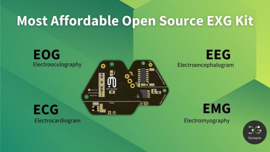
EXG Synapse — DIY Neuroscience Kit | HCI/BCI & Robotics for Beginners
Neuphony Synapse has comprehensive biopotential signal compatibility, covering ECG, EEG, EOG, and EMG, ensures a versatile solution for various physiological monitoring applications. It seamlessly pairs with any MCU featuring ADC, expanding compatibility across platforms like Arduino, ESP32, STM32, and more. Enjoy flexibility with an optional bypass of the bandpass filter allowing tailored signal output for diverse analysis.
Technical Specifications:
Input Voltage: 3.3V
Input Impedance: 20⁹ Ω
Compatible Hardware: Any ADC input
Biopotentials: ECG EMG, EOG, or EEG (configurable bandpass) | By default configured for a bandwidth of 1.6Hz to 47Hz and Gain 50
No. of channels: 1
Electrodes: 3
Dimensions: 30.0 x 33.0 mm
Open Source: Hardware
Very Compact and space-utilized EXG Synapse
What’s Inside the Kit?:
We offer three types of packages i.e. Explorer Edition, Innovator Bundle & Pioneer Pro Kit. Based on the package you purchase, you’ll get the following components for your DIY Neuroscience Kit.
EXG Synapse PCB
Medical EXG Sensors
Wet Wipes
Nuprep Gel
Snap Cable
Head Strap
Jumper Cable
Straight Pin Header
Angeled Pin Header
Resistors (1MR, 1.5MR, 1.8MR, 2.1MR)
Capacitors (3nF, 0.1uF, 0.2uF, 0.5uF)
ESP32 (with Micro USB cable)
Dry Sensors
more info:https://neuphony.com/product/exg-synapse/
2 notes
·
View notes
Text
EduExo Pro is an Arduino-controlled robotic exoskeleton kit that’s now on Kickstarter
Admit it, you have dreamed of wearing something like Tony Stark’s Iron Man suit. Sadly, that technology is fictional and real world exoskeleton suits are expensive. But a Swiss company called Auxivo wants to make exoskeletons available to educators, students, and hobbyists. To make that happen, they’re releasing their new EduExo Pro wearable robotic exoskeleton kit.
The EduExo Pro is available on Kickstarter to backers in a variety of packages, from a DIY version to a complete, assembled arm. Whichever option you choose, you will end up with a robotic exoskeleton arm that straps onto your own arm to enhance your strength. It has steel load-bearing structural parts and ball bearings on the joints. The shoulder joint has a heavy spring to provide assistance, while the elbow joint utilizes a powerful stepper motor.
An Arduino Uno board controls the stepper motor. It receives data from two sensors: a potentiometer to detect the elbow joint angle and an EMG (electromyography) sensor to monitor bicep muscle activity. The latter can detect when the wearer is flexing their bicep and then push power to the stepper motor. The arm also interacts with software running on a connected computer. For example, the EduExo Pro handbook provides instructions for integrating the arm with a Unity3D virtual reality game.
If you’re interested in trying the EduExo Pro for yourself, the Kickstarter campaign is running until July 29th.
The post EduExo Pro is an Arduino-controlled robotic exoskeleton kit that’s now on Kickstarter appeared first on Arduino Blog.
EduExo Pro is an Arduino-controlled robotic exoskeleton kit that’s now on Kickstarter was originally published on PlanetArduino
0 notes
Link
This project includes four main categories:1. Composite 2. Armband with EMG Sensors 3. Hardware and Assembly 4. Arduino and Circuits Together, all of these components show how there can be alterations to commonly done prosthetic pieces. The composite is done in a way that reduces the chance of fract... By: carley.pawliski Continue Reading » from Instructables: exploring https://ift.tt/33tkeZ9 via IFTTT
0 notes
Text
Making music with your muscles!
After being inspired by an Old Spice commercial where actor Terry Crews plays music with his muscles and EMG sensors, hacker Julio David Barriga decided to do the same thing using an Arduino.
While Crews’ setup involves an entire one-man band, Barriga’s system is greatly simplified, detecting the amplitude of the electrical signals emanating from his bicep. An Arduino Uno is then used to translate this signal into output notes on a small speaker, either as varying frequencies in the first video below, or as actual notes on the C major scale in the second.
The project write-up outlines a simple to implementation with a pre-built MyoWare sensor assembly, as well as a way to build own if you’d like to learn more about this technology.
youtube
youtube
Making music with your muscles! was originally published on PlanetArduino
0 notes