#patch panel wall mount bracket
Explore tagged Tumblr posts
Visit Tumblr Blog
Explore Tumblr blogs with no restrictions, modern design and the best experience.
Last Seen Tumblr Blogs


Fun Fact
130K people were victims of a chain letter scam that affected Tumblr in May 2011.
Text
The Ultimate Guide to Accordion Window Installation
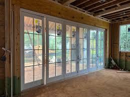
Accordion windows are a fantastic way to enhance your home’s aesthetic and functionality. Whether you're looking to open up your living space or create a seamless indoor-outdoor connection, accordion windows provide the flexibility and beauty you need. In this Ultimate Guide to Accordion Window Installation, we’ll walk you through every step to ensure a successful setup.
1. Plan and Measure Your Space
Before beginning installation, measure your window opening carefully to determine the correct window size. Take note of the height, width, and any potential obstructions around the opening. Ensure there is enough room for the folding panels to slide smoothly.
2. Choose the Right Accordion Window
Selecting the perfect accordion window is key to a successful installation. Choose a material that suits your climate and home design—aluminum, vinyl, and wood are common options. Decide on the number of panels based on the width of the opening, and ensure you’re selecting a high-quality, energy-efficient window.
3. Gather Tools and Materials
You’ll need a variety of tools to install accordion windows, including a tape measure, level, drill, screwdriver, mounting brackets, caulk, and weatherstripping. Having all your tools ready will streamline the process.
4. Remove Existing Windows (If Necessary)
If you’re replacing an old window, carefully remove the existing frame. Make sure to patch any holes or imperfections in the surrounding wall. Clean the area thoroughly to create a solid base for your new accordion window.
5. Install the Window Frame
Start by installing the window frame into the opening. Position it carefully and use a level to make sure it’s perfectly aligned. Secure the frame with screws or mounting brackets, ensuring it's firmly in place. Proper alignment at this stage is crucial for the smooth operation of the accordion panels.
6. Install the Track System
The track system is what allows the accordion window panels to slide open and closed. Attach the track to the frame according to the manufacturer’s instructions. Ensure the track is level and securely fastened, as it will determine how well the window opens and closes.
7. Hang the Accordion Panels
With the track system in place, carefully hang the accordion panels on the track. Start at one end and move toward the other, making sure each panel slides easily. It’s important to test the movement at this stage to ensure smooth operation.
8. Secure the Panels and Add Finishing Touches
Once all the panels are in place, tighten any screws or fasteners to secure them. Apply caulk around the edges of the window frame to seal any gaps, which will improve insulation and prevent drafts. Consider adding weatherstripping to enhance energy efficiency.
9. Test the Window
Open and close the accordion window several times to ensure it operates smoothly. Check for any resistance or sticking, and adjust the panels or track if necessary. Make sure the window locks securely in place for added safety.
10. Clean and Maintain
Once your accordion window is installed, clean the glass and frame, and regularly maintain the tracks to prevent dirt buildup. Perform occasional checks to ensure everything is working properly.
By following these steps, you’ll enjoy a successful accordion window installation that enhances your home with added style, functionality, and energy efficiency.
#AccordionWindows#HomeImprovement#WindowInstallation#DIYWindows#HomeRenovation#EnergyEfficiency#Windows#HomeUpgrade
0 notes

Text
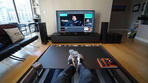
10 Actions to a Standard HDTV Configuration
If you are a first-time proprietor of an HDTV, upgrading your old HDTV or changing that old tube TELEVISION below are ten suggestions to a basic HDTV setup. These must help you obtain one of the most out of your brand-new HDTV and also give you the best possible image top quality.
This Just how To post is contacted give guidance for attaching your HDTV to a cable/satellite box as well as a Blu-ray DVD gamer. Future short articles will discuss exactly how to link Surround Sound Systems, Noise Bars, Wi-Fi (for Wi-Fi allowed HDTVs & Blu-ray players) and Game Consoles.
Take the TV out the box
Yes this is noticeable, but a word of caution. Suppliers like to pack the components needed to construct your TELEVISION in very odd areas. They make use of tape to hold the components safely and also sometimes the parts are light and also don't make any sound as you unpack your TV.
Thoroughly seek elements on each item of Styrofoam in package Ultimately, don't throw away package up until the TV is entirely set up and working, directly in an instance.
I am constructing the parts in package.
There are lots of various pedestals for flat screen Televisions. Each manufacturer has its very own foundation, some suppliers also have numerous kinds of foundations depending upon the TELEVISION design. Here are web links to a few of the most popular sorts of Samsung, LG, Panasonic and Sony instructions. The best thing to do is adhere to the guidelines that featured your TV to put together the stand. If you're wall surface placing it after that keep the components away for the future.
The back panel
There are some adapters back there but just a couple of are made use of in a standard High Definition arrangement.
RF Jack Used to connect an Antenna or cord service where a box is not needed
HDMI port. This is the preferred input for an HDTV. If you want the most effective picture you can have this is the one to utilise.
RCA Composite Video Clip. This is the traditional adapter. Utilised to attach old VCRs or DVDs. (red, white & yellow).
RCA Element Video Clip. These are the old analog HD connectors (red, environment-friendly, blue).
VGA Port. If you wish to attach your laptop or desktop computer this is where you connect it using a VGA wire.
S-Video.An old cord kind. Not the earliest, yet close. I used to be preferred on VHS video cameras as well as gamers among others.
PC Audio In. Link your laptop or desktop computer below using a 1/8"( 3.5 mm) patch cord. Audio from your computer system will originate from the TV.
This one is not numbered yet it remains in the lower left. Coaxial adapter.It is used for linking a powered subwoofer.
Above is a complete listing of all the jacks displayed in the picture. Listed below are the studs you will certainly need to complete your links.
# 1 RF Jack. This is utilised if you can receive HDTV over the air and don't use a set-top box (cable/satellite).
# 2 HDMI port. This is the favoured input for HDTV. If you desire the best image this is the one to use.
# 4 Element Video.Still made use of by some pc gaming systems.
Gather the materials as well as devices.
Cord and Satellite provider bring wires with them when linking a new solution. Nevertheless, most only utilise the older Component Video adapters as well as bill extra if you want the much better HDMI cable. If you had your box installed before you had HDTV after that you possibly have an old RF coax cord( # 1) or composite video clip wire 3.

If you didn't get cables when you purchased your equipment or, as mentioned above, you're upgrading from a non-HD TELEVISION currently is the moment to head out and also shop for your cables. In, HDMI Cable, Why do I require one? I cover some basic knowledge you'll need when purchasing your HDMI cords.
If you are wall surface mounting the TV then you'll require to choose which installing style you'll want. In The 3 Main Types Of TV Brackets there is an excellent introduction of the distinction between the braces.
Video Resource makes all the difference.
If you have not already done so, you ought to get a new HD set-top box from your satellite or wire service provider. Without one you'll never actually get an excellent picture. It might cost a bit much more every month, however the distinction in the image will certainly be worth the money.
I am placing every little thing in place.
If you are wall placing, then the wall mount must already remain in the area. I would certainly recommend including a wall surface rack to hold the cable/satellite box as well as the DVD right below the TV.
If you are setting up the TELEVISION on a stand after that it should be installed at eye degree for the best watching angle. Position your box and DVD where you want however be aware of the size of your cable televisions. I such as utilising a 3-foot cable to keep the added cable at a minimum, however this requires every little thing to be close and leaves no area to serpent the cord around shelves.
The Fundamental HDTV Setup.
At this point you need to have all the necessary parts to arrangement and also program your new TELEVISION. TV's with more than one HDMI have them phoned number. This will be necessary later when setting your TELEVISION.
Attach the first HDMI wire to HDMI1 if your TELEVISION has more than one connector. Number 2.
Place the Cable/Satellite box where you want it and also connect the HDMI cable television to it. Typically there is just one HDMI adapter in the back of the box.
If you're installing a Blu-Ray DVD gamer follow the same procedure.
Link the 2nd HDMI cable to HDMI2 if your TV has more than one connector. It's the reduced port in Number 2.
Put the Blu-Ray DVD player where you desire it and also link the HDMI cable to it. Again, typically there is just one HDMI adapter in the rear of the package.
If your TELEVISION doesn't have a second HDMI after that you can make use of the component video clip wires. DVD gamers are still being made with the older component adapters (# 4) (in the meantime anyhow). These are examples of the rear panel of the devices. Your actual boardmy vary but the standard jacks will exist.
Examining and Configuring the TELEVISION.
To verify every little thing is attached, begin by turning on the satellite/cable box. Using the TELEVISION's remote, push the "Resource" or "Input" button till you see HDMI1. Offering package is working, you must see as well as hear regular TV show programs.
The following power on the DVD/Blu-Ray, don't bother with placing in a disc the menu will certainly be all we need to test it. Once again press the "Resource" or "Input" on the satellite/cable box up until you see HDMI2. You need to see something different on the display currently. If it's black after that attempt placing a disc to make sure the player is functioning. As long as you can see something like a food selection or a movie you've hooked things up correctly.
Configuring the Universal Remote.
The last point you need to do is configure the satellite/cable box's global remote to collaborate with your TELEVISION and DVD player. This component differs a fair bit due to the many various companies as well as the several models of boxes they provide. Right here is a list of universal remote programs directions and also codes.
Last ideas.
That about does it for now.Time to kick back and also appreciate your brand-new HDTV Entertainment System. In the future you may wish to explore boosting the noise. There are numerous choices from full 7.1 border sound systems to the primary noise bar.
Lately installed a brand-new HDTV? Share your experienced right here for the advantage of other new HDTV proprietors.
1 note
·
View note
Text
How To Remove Vivint Doorbell Camera From Wall?
Vivint doorbell cameras are excellent security devices that provide an added level of safety to your home. However, there may come a time when you need to remove the camera from the wall. For instance, You may be moving to a new home, Home renovation is needed, or you want to reposition the camera to get a better view. Whatever the reason, it's important to know how to safely remove the Vivint doorbell camera from the wall without causing any damage. Key Takeaways: Remove Vivint Doorbell Camera From Wall in a few steps: Turn off your Vivint Doorbell camera system Disconnect the wiring and remove power source. Remove the doorbell camera cover Remove Screws and Wires Remove the Mounting Bracket Reassemble your panel
Remove Vivint Doorbell Camera From Wall in 7 Steps
Arrange Necessary Tools Before, starting the removal process of your Vivint Doorbell Camera, make sure that you arrange the relevant tools as mentioned below: Philips screwdriver Pair of gloves A tester to ensure 0 Current Disable Vivint smart home system The Vivint Doorbell system is quite intelligent and it is Theft-proof. Actually, Vivint Doorbell system connects to sensors that produce an alarm in case the sensors feel touched. Now, Go to your Vivint app and remove the warning notification which means that you have disabled the Vivint system. You can check the setting in the app and confirm the whole Vivint system has been disabled and removed carefully.

Turn off the Power Make sure that you remove your doorbell camera from the power source carefully. Remove all the direct wiring from the outlet. Locate the circuit breaker that controls the power to the camera, and turn it off. This will ensure that you can safely remove the camera without the risk of electrocution. Related: How to Remove Nest Doorbell Note: Always set aside your Doorbell’s wiring and connection resources to ensure that no live wire can harm you. Remove the Panel Cover First, check the current supply has been stopped and it is not passing through the doorbell because, even after removing the power source, there is a possibility of current. So, you can use a Tester and if tester’s light blinks, it means the current is still passing through. Now, when you have cleared and ensured that there is no current, take a screwdriver and remove the screws from the panel. Push the tab gently and pull the cover out and down. Hang the panel cover on the backplate.

Remove the Mounting Bracket When you have opened the panel cover, you will see two sets of wires. One is used to direct the current to the circuit while the other wire is for batteries. - Power wires are connecting externally. - Battery wires are insulated internally in the doorbell. Identify Which Ring Doorbell You Have Now, you have to remove the external wires connecting to the doorbell. You can use a simple tool such as a screwdriver to remove the power wires from the panel. Don’t forget to remove any cable wiring connecting to the outside internet mediums.

Here, you can see screws that have tightened the doorbell with the wall. Once, you remove the screws, you can detach the doorbell and mounting plate from the wall.

Disconnect Power Wires When you remove the mounting bracket from the wall, you can see wires from the wall which are known as power wires to supply current to the doorbell. Pull out all the wires and save them aside to use again when you re-install the doorbell.

Patch the Holes With the mounting bracket removed, you may be left with holes in your wall. To patch these holes, you'll need some spackle or putty. Contact Us If you need any further assistance regarding your Vivint Doorbell, please contact Vivint. Enjoy Reading Too: Can I View Ring Doorbell on TV How my Dog sees himself when Doorbell rings How To Sneak Past Ring Doorbell
Frequently Asked Questions
How do I delete my doorbell camera? Go to your doorbell app on your mobile. Find settings from the menu. Click Delete from the settings. Now, your doorbell account will be removed from the app. Can you delete camera footage on Vivint? No, camera footage or any activity on Vivint can’t be edited or deleted. Do I need any special tools to remove the Vivint doorbell camera from the wall? No, you don't need any special tools to remove the camera. A screwdriver and wire cutter or pliers should be What should I do if I accidentally damage the wires while removing the Vivint doorbell camera? If you accidentally damage the wires, you may need to hire a professional electrician to repair them. Avoid using the camera until the wires are properly repaired to prevent any electrical hazards. Can I reuse the mounting bracket after removing it from the wall? Yes, you can reuse the mounting bracket if it's still in good condition. Make sure to keep it in a safe place until you're ready to reinstall the camera. Can I remove the Vivint doorbell camera from the wall without turning off the power supply? No, it's essential to turn off the power supply before removing the camera to avoid damaging the device or receiving an electric shock. What is the Voice alert of the Vivint doorbell camera? The voice alert feature of the Vivint doorbell camera allows the device to provide an audible notification when someone presses the doorbell or when motion is detected. This notification can be heard inside and outside the home and can be customized to play a pre-recorded or a default message. For example, when someone presses the doorbell, the device will play a chime sound and say "Someone is at the door." If a motion is detected, the device will play a different sound and say "Motion detected at the front door." Does Vivint Doorbell Camera Record All the Time? Vivint Doorbell only records when it detects an event such as a visitor passing through and all its recording is saved through cloud storage. Can I Still Use My Vivint Camera Without Service? You can use the Vivint camera without the internet. But, if you want to view the Live interface, connect it to the internet. Does Vivint Remove Equipment? You can either remove your system yourself or a Smart Home Pro can professionally remove your equipment for you for only $149. About Author Read the full article
0 notes
Text
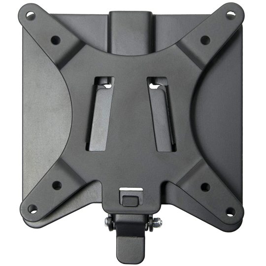
How to install wall mount patch panels by yourself?
Wall mount brackets help keep the telecoms room's critical floor area free. Available with either a right- or left-handed hinge, allowing full access to the patch panel's back. DME Prolink provides a range of wall mount bracket in Dubai.
While big racks and cabinets are frequently used in data centers and other tech rooms to store equipment, there are occasions when a more compact option is required. It may be unnecessary to install something as straightforward as a single patch panel in a full-fledged rack or cabinet. A bracket is frequently the ideal choice to conserve space and maintain the simple installation.
Once a suitable location has been chosen, installing a bracket is a very simple undertaking. The necessary screws, washers, and wall anchors will be included with the bracket itself. Other than that, an installation only requires a few straightforward tools.
Here are the steps to follow:
Gathering The Tools: Gathering the tools will be the only additional preparation required because the bracket includes all of the little parts required for installation. A drill with a drill bit, a hammer, a screwdriver, a level, and a pencil are required for users.
Leveling The Bracket: Use the level to locate the level point while holding the bracket up against the wall. By doing this, you can make sure the bracket is exactly straight and won't appear crooked when it is attached.
Marking the Drill Holes: The screw holes on the back of the bracket should be marked with the pencil while it is still level.
Drilling The Holes: Drill through the pencil markings on the wall using the drill and drill bit.
Securing The Wall Anchors: Fill the holes with the wall anchors that were included with the bracket. To make sure the anchors are firmly fastened, they will need to be pounded into position.
Attaching the Bracket: Over the wall screws that were included with the bracket, place the washers. Align the screw holes on the bracket with the wall anchors while you hold it against the wall. Using the screwdriver, tighten each screw after inserting it into an anchor.
Installing The Patch Panel: The patch panel should be fastened to the bracket using the tiny rack screws. Tighten the screws with a screwdriver for a reliable connection.
A Wall Mount Fiber Patch Panel may be the perfect solution for terminating your cables and securing your network if desk or rack space is an issue. You may learn more about which wall-mount patch panel is best for you by looking at each patch panel's rating, which can be either outdoor or indoor. Wall-mount patch panels offer dust-tight and lockable solutions that can shield your network from outside interference.
View the broad collection of wall mount in Dubai offered by DME Prolink. For the finest in connectivity, we carry the full range of datacom wire and cable solutions as well as supplementary accessories. DME Prolink provides a wide range of Datacom and ELV Transmission Solutions for unmatched connection that may be used in a variety of verticals according to regional customs.
0 notes
Text
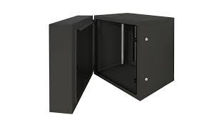
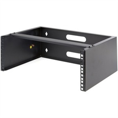
4U Wallmount Rack 13.78" Deep
4U Wallmount Rack 13.78″ Deep
Startech WALLMOUNT4 – 4U wall mount rack (19 inch wide) has a max. mounting depth of 13.78″ [35 cm] and a max. weight capacity of 44lbs [20kg] – Wall mounted patch panel bracket for networking equipment has pre-drilled holes 16″ apart for standard drywall framework – Incl. anchors/screws to install bracket to the wall, Incl. equipment mounting hardware – Durable wallmount rack made of cold rolled…
View On WordPress
0 notes
Text
Part 15: The Final Dungeon
In this post, I make a guide about the last dungeon found in the game; but we don’t actually fight the “final boss” until much, much later on.
If you don’t know what this is about, please refer to this previous post.
[Any new comments by me will be designated by brackets.]
Upon entering the final area of the game, you’ll be greeted with this sight:

A mountain high up in the clouds...
Taking the stairs down, you will then see this:

Two paths.

...Two more paths?

Just how many pathways are there?!

Yeah, there's only one real stairway down. The rest of the paths lead to dead ends. Though you should still check out the pots as most have items. (So it's not a complete waste of time if you take the wrong path.)
Just take the leftmost path to begin with, then continue taking the right path when it branches. That should lead you to the stairs.
The monsters here are pretty easy if your party's level is in the 50s.

Another maze like area.
I actually highly recommended that you take Fugen and Nataku into this dungeon on your first time through, and collect all the treasure you can. You can create shortcuts on those patches in the water with Fugen’s “action button” ability.

The next room has spikes. Tons of spikes. And it's laid out in a way where you only have one path to take. The producers seriously tried to lengthen this dungeon a lot using cheap tricks. Be aware that you’ll still be having random encounters in every room of this dungeon.
Stepping on the spikes results in everyone in your party losing 1000 HP with each step. Saying "ouch" is an understatement.
[The game never actually tells you this, but if you have Nataku in your party, you’re able to walk over spikes without taking damage. I assume Nataku just carries your entire party on his back over the spikes or something.]

But seriously though, look at all these spikes. After taking the stairs in the Spike Room of Death, you will see this:


This game loves Yin-yang symbols.

Tensho POUNDS the ground AGAIN. For some reason.


This ends up creating a big crack right down the middle of this room.


Dakki shows up, and converses with Tensho. Some dialogue choices appear but it doesn’t seem to matter which choice you pick. There’s no difference in the conversation text that appears afterwards.

Shinkyohyou arrives on the scene!
Then Kibi appears out of thin air while Dakki disappears.

Shinkyohyou and Kibi fight. Sadly, you do not get to fight Kibi yourself.
Shinkyohyou easily dodges Kibi’s attack and lightning bolts her.

She takes the attack less than well. Then she promptly disappears (deeper into the dungeon, I assume), and so does Shinkyohyou.
You automatically get warped back to Mount Kongrong 2 because CUTSCENE.
Tensho has a conversation with Taiitsu and Youzen.

Suddenly, Nentou appears! He returns with Soushou, who's apparently finished his training.
A loooong conversation follows. After that, return to the final dungeon. There are still some things there left to do (although we still won't be fighting the final boss just yet).
Yes, you're going to have to go through the annoying first half of the dungeon again... And don't even get me started on the SECOND HALF.
When you come back to the crack in the ground, step ON the crack. Yes.
You'll be transported here:

It kind of looks like the interior of Hourai Island, except with much less purprle.
These next few levels are essentially mazes. There are also chests scattered about, and once again, you might as well take them all the first time through.
If you're looking for a way to the stairs, just take a left, go up, then down, all the way to the wall at the bottom. Go right, and take the first path up that opens up. After that, the path is pretty straight-forward. Unnecessarily long and annoying, but straight forward, yes.

Oh hey, what's this?

A surprise mid-boss fight!

This dude’s name is Koukaku, and he’s the enemy that Cho Kei fought in the coliseum matches (volume 21 of the manga).

His special move is... he heals himself. While annoying, it could have been worse.
Have Tensho and co. special attack him like there's no tomorrow, and he should go down pretty easily.
After beating Koukaku and stepping on the downwards warp panel, you get to go through yet another maze.
Go down, right, take the path up, left, follow the path through, up, right, down, and here we are! (Yeah, probably really confusing if you're just reading this walkthrough, but you'll understand what I mean when you're playing the game.)

Another yokai enemy!


You now get to fight Kyuuin, the earthwrom yokai senin that Tensho single-handedly houshined as a kid.

Yeah, the dude’s pretty pathetic for a mid-boss. His special attack is weak and only damages one person.
Just use your own, superior special attacks to defeat him.

On the next floor are vending machines! You can buy things here if you have the money and the space.

All the way to the left and up are places where you can heal HP and EXP! Neat! (You'll have to touch the one on the left for it to work.)

Going down from there... If you still have Fugen, you can get an item from the pool of water here.

Spikes! If you still have Nataku, you can get...

Three treasure chests! Wow.

To get to the next floor, you’ll have to defeat yet another yokai mid-boss.


Is he a pile of slime of an bloated looking dust cloud? WHO KNOWS?
[In all seriousness, this is Bazen, the “formless-type” yokai. He was pretty violently defeated by Youzen’s Rikukonhan. Technically he shouldn’t have been revived either since his soul wasn’t sent to the Houshindai...]

Special attack him and watch your health. Bazen’s pretty strong compared to his other two companions.
Taking the warp panel down, yet another room! And what's this?

Apparently, it's a table. You can pick up an item from the cube thing if you have room. Directly opposite are two more chests!

One final yokai mid-boss...

It’s Chintou! One of Taikoubou’s first enemies (and houshins).


At the risk of sounding repetitive... SPECIAL ATTACK SPECIAL ATTACK SPECIAL ATTACK. And heal when you need to.
After that, the warp panel's clear!

Walking down... THIS is the final warp panel. After this, it's the point of no return and the FINAL BOSS.
...Which we are not going to do just yet. Quick backtrack out of here!

You can use the item highlighted above to warp out of any dungeon quickly. This is really nice for the final dungeon, seeing as how annoyingly long it is to go in and out.
[Now you might be wondering, “why aren’t we defeating the final boss now?”
To that, I say:
1) The final boss is EXTREMELY hard to beat, so you’ll most likely have to do tons of grinding unless the party you plan to bring to the fight are already leveled up to their 60s or 70s.
2) Senkaiden 2 doesn’t have a post-game. The game just automatically ends once you defeat the final boss. If you start up the game again, you’ll be spit out at the place you last saved at before defeating the final boss.
3) There are TONS of side-quests that you can complete at this point in the game, involving characters gaining new ultimate and special attacks and it’s just really cool. I’ll be covering all the ones that I’ve been able to find in the next few posts.]
To be continued...
1 note
·
View note

Text
Jingchengmei (2 Pack) 2U Foldable 44 Pounds Loading Vertical Wall Mount Patch Panel Bracket Steel Underdesk Mountable Server Rack for 19inch Network, Server and Data Equipment, Black by Jingchengmei
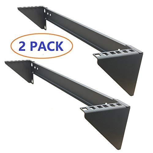
We are proud to review the amazing Jingchengmei (2 Pack) 2U Foldable 44 Pounds Loading Vertical Wall Mount Patch Panel Bracket Steel Underdesk Mountable Server Rack for 19inch Network, Server and Data Equipment, Black.
With so many on offer recently, it is great to have a product you can have faith of durability. The Jingchengmei (2 Pack) 2U Foldable 44 Pounds Loading Vertical Wall Mount Patch Panel Bracket Steel Underdesk Mountable Server Rack for 19inch Network, Server and Data Equipment, Black is certainly that and will be a excellent buy.
For this price, the Jingchengmei (2 Pack) 2U Foldable 44 Pounds Loading Vertical Wall Mount Patch Panel Bracket Steel Underdesk Mountable Server Rack for 19inch Network, Server and Data Equipment, Black comes highly respected and is always a popular choice with many people. Jingchengmei have included some excellent touches and this means great value.
The article was originally published here!
0 notes
Text
StarTech.com 2U 19in Hinged Wall Mount Bracket for Patch Panels - 2U Wallmount Bracket - 2U Wall Bracket

0 notes
Text
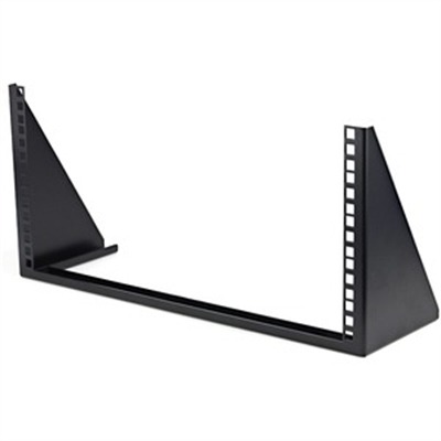
Startech RK519WALLV - Low profile 5U vertical patch panel bracket to mount server-data-networking or AV equipment - Can be mounted vertically where standard racks are not practical - TAA compliant and constructed to EIA-310 19 inch rack standards and a solid steel open frame design with a weight capacity of 200lb - Ships fully assembled with cage screws for mounting equipment and 1 wood screws for mounting the rack - The wall mounting holes on the 5U vertical mountable rack bracket are 16 center to center.
Startech RK519WALLV – Low profile 5U vertical patch panel bracket to mount server-data-networking or AV equipment – Can be mounted vertically where standard racks are not practical – TAA compliant and constructed to EIA-310 19 inch rack standards and a solid steel open frame design with a weight capacity of 200lb – Ships fully assembled with cage screws for mounting equipment and 1 wood screws for mounting the rack – The wall mounting holes on the 5U vertical mountable rack bracket are 16 center to center.
5U Wall Mount Rack
View On WordPress
0 notes
Photo
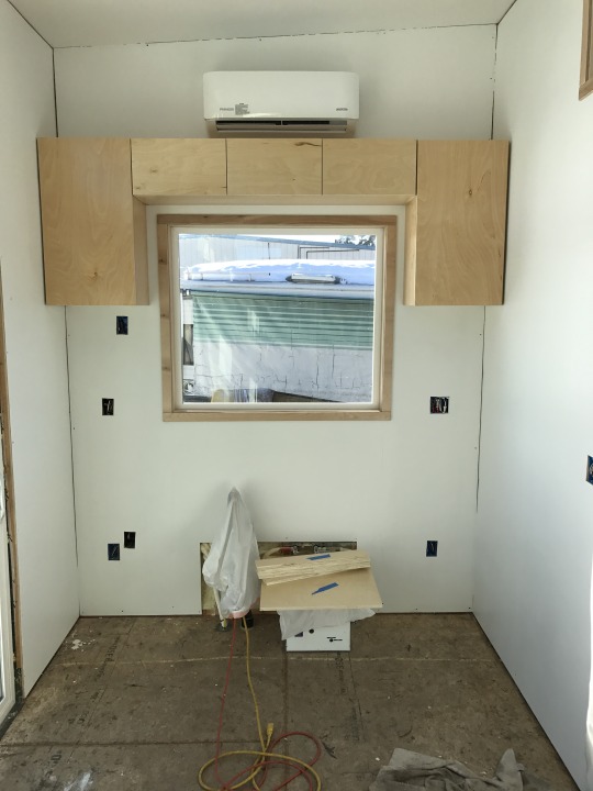
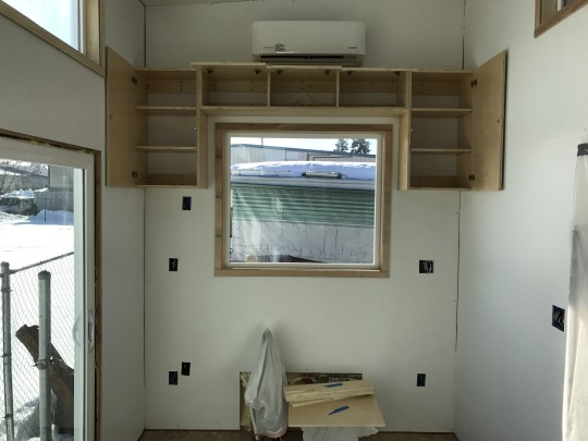
Building the Baja box kitchen (phase 1 of 4)
Although all my cabinetry will be built in, the kitchen cabinetry is the only real section that has to be done before and under the finish flooring. So phase one starts this week. There will be 4 phases that I can think of… 1, upper cabinets, 2, base cabinets, 3, counter top, and 4, installing sink, stovetop, and appliances. Well if u count final electrical and plumbing hookup then maybe there’s 5 phases but part 5 will come way further down the road so I’ll skip that for now.
Part 1: Designing, building, hanging and finishing upper cabinetry.
This was my very first go around with any kind of cabinetry/joinery work, but I’m keeping it very simple, clean and staying with the minimalist theme from the rest of the house’s aesthetic, so it shouldn’t be too complicated technique-wise. I’m just using ¾ inch finished birch plywood (my favorite, as usual 😉) and glueing/screwing with pocket holes throughout. I won’t have all that much storage space in my base cabinets because a lot of it is occupied by my fridge and freezer, hot water heater and plumbing mess, so I wanted to maximize the vertical storage space by building full wrap around cabinets surrounding the window. But it’s a tiny house of course so they r miniature versions haha. The side units have three removable shelves each and then the upper bank of cabinets has three 10 inch compartments. I mounted the door hinges on the top for the upper bank so that the doors swing up vertically and make it easier to access. They r super tall though, it’s a good thing I have go-go gadget arms because a normal height person might have a little trouble getting up to the top cabinets without some kind of step stool thingy, but it works for me so all good in the hood.
There is a butt load of math involved in building custom cabinetry, but I’m actually really enjoying it so far, it’s very puzzle-like. The most stressful part of this little bit was hanging them on the wall. First of all I had to hang them by myself which was a puzzle in itself not only physically getting them up there level and plumb and driving screws at the same time, but also, there is a TON of electrical work and plumbing lines in this wall in particular, so i was pretty terrified of driving screws into any wires or plumbing. I was as careful as I could be I think, but like everything else I’m pretty inexperienced with this stuff and locating studs over finished paneling is never an exact science anyway. I Guess I won’t know until I finally go to do final electrical and plumbing installs if everything’s safe and intact. Ugh, I’m just praying it’s ok…
From there it was just about a final sanding, a little poly-finish, and patching up some rouge screw holes/clumsy dings in the walls and paint. Well actually this part isn’t still 100% done. I’m still going to have two open face shelves mounted with angle brackets underneath either side cabinet (the one on the left will mount my microwave on the wall and the one on the right will just be a miscellaneous storage shelf). I still have to pick up the parts and build those though so I guess this is more like the “tiny kitchen build part 0.75”.
I dunno why but these pictures r kind of distorted and have some weird fish eye effect going on but u get the idea. Next week it’s base cabinets.
1 note
·
View note
Text
JFT-03 Series Digital Programmable Time Switch
JFT-03 SeriesDigital Programmable Time Switch
Introduction
JFT series digital programmable time-controlled switch can automatically turn on or off the power of various electrical equipment according to the time set by the user. JFT series microcomputer time-controlled switches are composed of LCD digital display, programmable IC chips, buttons, switch components, etc., which are widely used in street lights, neon lights, advertising signs, production equipment, assembly lines, broadcast equipment and other equipment. The JFT series time-controlled switch adopts a new patch technology, which can effectively avoid the phenomenon of false welding and missing welding, and has the characteristics of stable performance, low power consumption, and light weight. JFT-03 can be directly welded into the instrument, or be panel mounted with a contact bracket.
Parameters

JFT-03
Timer Range: 1min≤t≤168h (cycle work daily or weekly) Voltage: 110VAC, 220VAC/50Hz (or other customized voltage) Operation Temperature: -10℃~50℃ Operation Humidity: <95% Number of Settings: 10 groups per day Switching Capacity: 10A (resistive load) Contact Type:SPDT, 1 NO and 1 NC contact Battery: Built-in rechargeable Ni-MH battery Consumption Power: ≤5W Time Error: ≤2s/day (25℃) Weight:140g Dimensions: 48×48×96mm Mounting: Panel/Wall
Dimensions & Wiring Diagram
JFT-03
1 DC power supply (as shown in Figure 1)
2 Single-phase AC power supply 2.1 Direct control method (as shown in Figure 2.1) Applicable objects: Loads with single-phase power supply, and the power consumption does not exceed the rated switching capacity of the switch. 2.1 Single-phase expansion method (as shown in Figure 2.2) Applicable object: Load with single-phase power supply, but the power consumption exceeds the rated switching capacity of this switch. The capacity expansion method should be adopted for inductive loads.
3 Three-phase AC power supply (as shown in Figure 3) Need to connect a three-phase AC contactor (coil voltage is 220VAC/50HZ).

JFT-03 dimensions and wiring diagram
Instructions For Use (How to set)
Please make sure that you have understood the functions of all the buttons on the panel (button area), and perform the actual operation according to the instructions.
1 Description of buttons and indicators
CLOCK (): Press to display your local time (it should be set by yourself: you can press and hold the "CLOCK" key to enter the "Time Adjustment Mode", and adjust the "WEEK", "HOUR", and "MINUTE" key to set the local time). PS: If no operation is performed within 30 seconds, the timer switch will automatically display the local time. TIMER(): Press to enter the "Editing Mode", and then set the time to switch the load by adjusting the "WEEK", "HOUR", and "MINUTE" key. WEEK (D+): Adjust week or day. There are various working modes, such as "Five-day Mode" (Monday to Friday), "Six-day Mode" (Monday to Saturday), "Weekend Mode" (Saturday, Sunday), "Daily Mode" (Monday to Sunday), and "Three-day Mode" (Mon-Wed-Fri; Tue-Thu-Sat; Mon-Tue-Wed; Thu-Fri-Sat). HOUR (H+): Adjust hour. MINUTE (M+): Adjust minute. AUTO/MANU (MANUAL): Switch the three switching mode of "ON", "AUTO" and "OFF". For multiple-output timer switches, the output combination can be configured through the "AUTO/MANU" key when in the "Editing Mode" RESET/RECALL (Cancel/Restore, C/R): Press to cancel or restore the timing setting. PS: For products with button lock function, press the " RESET/RECALL " key four times to lock or unlock all buttons. C: Long press the "C" key to clear all settings of the timer switch. POWER LED: When the Power LED (red) is on, it means that the timer switch has been successfully connected to the power source. WORK LED: When the Power LED (red) and the Work LED (green) are on at the same time, it means that the load is powered on.
2 Operating instructionsStep 1. Timing setting (on)
Press the " TIMER " button to enter the "Editing Mode". At this time, the "1ON" symbol will appear at the bottom left of the LCD screen (that is, the first time to turn on the load, as shown in Figure 4), and then press the "WEEK" to select Working Mode, and then press the "HOUR" and "MINUTE" keys to input the required switching on time.
Step 2. Timing setting (off)
Press the " TIMER " button again, the "1OFF" symbol will appear at the bottom left of the LCD screen (that is, the first time to turn off the load, as shown in Figure 5), and then press the "WEEK" to select Working Mode, and then press the "HOUR" and "MINUTE" keys to input the required switching off time. At this time, the first group of timing setting has been completed.

Timing Setting 1
Step 3. Timing setting (number of groups)
After completing the first group of timing setting, press the "TIMER" button again, the LCD display will show the "2ON" symbol, and you can set the second set of time setting. According to actual needs, you can repeat steps 1 and 2 to set many groups (the maximum programmable group number depends on the product's built-in chip). If you want to exit the "Editing Mode", you can press the "CLOCK" key to exit it.
Step 4. RESET/RECALL
After setting a group of time, for example, turn on the load at 18:30 every day (Figure 6), and turn off the load at 23:20 every day (Figure 7). If you want to cancel this group, you can press the "RESET/RECALL" button to delete this group of time settings. At this time, the group of time will be reset to the initial state, that is, "--: --" (Figure 4 and Figure 5). Under certain conditions (without any key operation or switching to other interfaces within 20 seconds after cancel operation), just press the "RESET/RECALL" button again to restore this group of time settings.
Step 5. AUTO/MANU
The timer switch has two switching modes: automatic and manual. In the automatic mode, the timer switch will be set according to the timing of steps 1 to 3, and the load will be automatically turned on or off at the corresponding time without human intervention. In manual mode, the load must be turned on or off by manual adjustment. The specific operations are as follows: 1) If you need to turn on the load manually, you can click the "AUTO/MANU" button to switch the "▼" symbol on the display to the "ON" position (Figure 8). At this time, the load will always be in the on state and cannot be turned off automatically. 2) If you need to turn off the load manually, you can click the "AUTO/MANU" button to switch the "▼" symbol on the display to the "OFF" position (Figure 9). At this time, the load will always be in the off state and cannot be turned on automatically. 3) If you need to switch the load automatically, you can click the "AUTO/MANU" button to switch the "▼" symbol on the display to the "AUTO" position (Figure 10). At this time, the working state of the load will be switching automatically according to the timing setting, without being interfered by humans.

Timing Setting 2
When you think there is a fault (FAQs)
Note: When the product fails, please disconnect the power first, and then check the equipment! 1 Check the week If the timer switch does not turn on or turn off the load at the set time, it may be that the "WEEK" is not adjusted correctly, please check or reset it according to the method introduced in "Timing Setting". 2 Check the time groups If the first point is confirmed to be correct, but the load still cannot be switched correctly on time, the reason will be that the extra time group has not been cancelled. Please refer to the method introduced in "Timing Setting" to delete it. PS: Only when the display shows "--: --", it means the time group is deleted successful; if it displays "00:00", it means 0 o'clock (24 o'clock), not the deleting success. 3 Check the switching mode If the above two points are confirmed to be correct, but the timer switch still does not work normally, it may be that the timer switch is working in "Manual Mode". You can first adjust the "AUTO/MANU" key to set the timer switch to the right working state of the load (ON or OFF), then switch to the "Automatic Mode". 4 Check the fuse If the above three points are correct and the timer switch still cannot work normally, please open the rear seat insurance cover (terminal cover) and check whether the fuse has been blown. If it is blown, please replace with a new 0.1A~0.3A fuse. 5 Check the power supply If the Work LED (or Output LED) is on when the timer switch is working, but the load cannot be switched normally, please check whether the voltage of the power supply is too low. If the timer switch is burned out, please check whether the power supply voltage exceeds the rated voltage of the product and whether the power cable is connected incorrectly. 6 Please replace the battery If the LCD screen does not display or the display is not clear, replace the battery with the same specification. (Only for timer switch with replaceable batteries) 7 Please contact us or local distributor If the fault cannot be eliminated by the above methods, please contact us or the distributor (dealer) in your local area.
Attentions
1 For those equipment (such as medical equipment and large equipment, etc.) that may cause life safety accidents or cause major harm to society due to the error of the timer switch, please do not choose this timer switch. 2 For those equipment (large heaters or cold storage, etc.) that may cause major property losses due to the error of the timer switch, ensure that there is sufficient design margin when using this timer switch, and take safeguard measures such as the double protection circuit. 3 Do not repair, disassemble or modify this timer switch by yourself. If you need to repair and check it, please be sure to entrust a dealership or other authorized unit. 4 Do not touch any terminal on the timer switch after it powered on. 5 This timer switch cannot work in humid, corrosive and high metal content gas environment. And do not let the timer switch come into contact with oil or water.
0 notes
Text
#gallery-0-5 { margin: auto; } #gallery-0-5 .gallery-item { float: left; margin-top: 10px; text-align: center; width: 33%; } #gallery-0-5 img { border: 2px solid #cfcfcf; } #gallery-0-5 .gallery-caption { margin-left: 0; } /* see gallery_shortcode() in wp-includes/media.php */
The STARTECH.COM advantage: StarTech.com offers a lifetime warranty and free lifetime technical support on this bracket and has been the choice of IT professionals and businesses for over 30 years. Sturdy construction: The 6U wall mounting bracket delivers a dependable equipment storage option, allowing you to wall mount equipment for a more efficient and accessible operating environment. Built to last: Made of sturdy cold rolled steel, you can rely on this mounting bracket to keep your network equipment safe and sound. This bracket is perfect in areas where space is at a premium. Optimized workspace: This 6U 12 inch deep wall mounting bracket has an open frame, 2 post design with a maximum mounting depth of 12 inch [34.6 centimeter] and a maximum weight capacity of 44.2 pounds [20 kilogram]. Easy to install: The 6U wall mounting bracket ships fully assembled and comes complete with 12x M6 Screws and 12x M6 Cage Nuts for easier installation, to save you the hassle of sourcing separate mounting hardware. [amz_corss_sell asin=”B07TZZZ47R”] StarTech.com Deep Wall Mounting Bracket for Patch Panel The STARTECH.COM advantage: StarTech.com offers a lifetime warranty and free lifetime technical support on this bracket and has been the choice of IT professionals and businesses for over 30 years.
0 notes
Link
สวยเริส ดีิสินค้า สุดยอด ของจริงแท้ไม่มีปลอม และที่สำคัญคุ้มต่อการรอค่อย เพราะ เพื่อนเคยซื้อแบบเดียวกันแต่ไม่ใช่ร้านนี้ ได้ของ ปลอมเกรดโห่ยเมี่ยมมา พอ มาเจอของผม มันบอกของแท้ เพราะน้ำหนักติดมือแบบเยี่ยมครับ
0 notes
Text
Monoprice Wall Plate mounting bracket
Monoprice Wall Plate Lowest Price: . Monoprice Wall Plate:Mounting Bracket for Patch Panel Punch-down Block.
0 notes