
Chronicling my adventures with Raspberry Pi and Arduino. Tangents to other top of mind topics likely. @vpkivimaki on Twitter
Don't wanna be here? Send us removal request.
Statistics
We looked inside some of the posts by tinkersnippets and here's what we found interesting.
Average Info
Notes Per Post
4
Likes Per Post
4
Reblog Per Post
0
Reply Per Post
0
Time Between Posts
3 days
Number of Posts By Type
Link
2
Text
6
Photo
1
Last Seen Tumblr Blogs


Fun Fact
Tumblr’s website traffic is steadily declining.
Link
Super-busy work week has kept me from getting the next post up, but in the meantime came across this piece of awesomeness: a downloadable book to teach Python programming using a version of Minecraft created specifically for Raspberry Pi.
0 notes
Text
How a 13-year old girl introduced me to microcontrollers
Only a few days after I had finished the BerryClip, Twitter led me to this video of Amy Mather, a 13-year old programming & Raspberry Pi enthusiast, explaining the projects she's done. What started out as curiosity in seeing how kids are learning programming with RasPi ended up with me learning something new about how to use the RasPi to interface with the external world. The news came at the 4:50 mark...
Amy had connected the RasPi to an Arduino, which in turn was controlling an LED matrix. Not being above from learning from 13-year olds, I decided to look into the Arduino.
Arduino is a family of microcontroller boards, while the Raspberry Pi is a computer in a small package. The two are good at different tasks, and complement each other. The Arduino is great for building interactive systems in the physical world, as it can interpret data from sensors and drive actuators like motors, and has plenty of connectors for these. The Arduino can also handle analog inputs, which Raspberry Pi cannot without breakout boards. (Temperature sensors and potentiometers are just a few examples of analog sensors.)
So, the Arduino is handy for interfacing with the external world, while RasPi is great as a compact software, processing & connectivity platform. I also liked the fact that unlike a breakout board for the RasPi, I could use the Arduino as a standalone prototyping platform. Two things support this: 1) the tools are very easy to set up on any desktop platform, and 2) the Arduino community is very active and it's most likely someone has already faced and solved the problem you're having with your project.
While shopping around for Arduino boards, I discovered the most excellent Arduino Starter Kit, which in additions to things like LEDs and buttons also includes a servo and a DC motor. Since my crazy project idea would require a motor of some sort, this was a brilliant find for getting some practice.
I managed to track down the kit from a nearby electronics retailer, and in a few days I held the package in my hands.
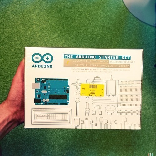
Next post will be looking inside the box.
2 notes
·
View notes
Text
Soldering time: Assembling the BerryClip
It was time to get ready for my first attempt at soldering a PCB. I had only ever soldered some random wires before, and was a bit intimidated at first by the precision required with the PCB.

The assembly instructions can be found on the Raspberry Pi Spy website. Thankfully, they're quite clear with good links to external sources on soldering. Also, used these instructions as an additional reference.
First, it was time to round up the gear. I had a few soldering irons tucked away, so retrieved them and chose a 15W one for the job. The guides recommended 60/40 solder for electronics, meaning the solder should contain 60% tin (Sn) and 40% lead (Pb). This meant a shopping trip, and found 60/40 solder with 1mm diameter. On the same trip, picked up a soldering iron stand, which also included alligator clips. The clips turned out to be helpful in keeping the PCB in place during soldering.

Grabbed a few more things before starting: small wire trimmers and a Scotch-Brite cleansing pad for cleaning the excess solder off the soldering iron.
So, time to solder the first joints. Started off with the resistors, as recommended by the guide.

I placed the component and twisted the leads to keep it in place. I then applied the iron to where the lead the solder pad meet, and slowly added some solder. The connection seemed to seal quite nicely, so pulled the solder away, followed by the iron a few seconds later, and repeated the process on the other side. After placing the remaining 330Ω resistors, this was the result.

I was happy with the result, but in retrospect I'm wondering whether what happened to the PCB coating is normal. Need to look into it. Regardless, I trimmed the leads, and while doing it realized my wire trimmers were basically trash. Made the decision then & there to invest in a decent pair to make future work easier and end results prettier.
Proceeded to place the rest of the components, while saving the connector for last. After soldering them on, I was proud of my minor achievement. LED6 looks a bit funny & crooked, but hey, it gives my BerryClip personality. ;)

The part I was really nerveous about was saved for last. The spacing of the holes with the 26-pin connector is quite narrow, so I was worried about shorting one of the connection. While soldering the pins, I found that the LEDs were intruding a bit and making the work slightly more difficult, but taking it slow the end result turned out just fine.

The instructions for the BerryClip mentioned using a multi-meter to check for short-circuits. I didn't have a multimeter handy at the time, but what the instructions refer to is a continuity check. Adafruit has a wonderful page explaining continuity and how to use a multimeter, which is worth checking out.
About the soldering iron I used: while the tip was a good size, it's detachable and doesn't have any sort of locking mechanism. The tip came loose a few times during soldering, and I had to push it back in place several times. Did the job, but very annoying, and will be looking for a replacement.
Anyhow, it was time to connect the BerryClip onto the GPIO on the Raspberry Pi and see if my soldering was any good! The webpage for BerryClip had ready-made Python scripts, which made it very easy to test the breakout board. Enter berryclip_09.py, and...
IT WORKED. :) Never been so happy about a bunch of blinking LEDs...
0 notes
Text
Choosing the first project
So, I had the Raspberry Pi set up and running Raspbian. Now what?
Going back to my original crazy thought of being able to control a robotic hand from my smartphone for the purpose of squeezing squaky toys, I started abstracting the specific idea to being able to control an external, motorized device from a smartphone. In order to make progress toward that goal, I started breaking down the problem into manageable chunks.
One piece of the puzzle was the communication between a smartphone (in this case a Windows Phone) and the RasPi. Both are WiFi-enabled, so that solves basics. After a bit of searching, I found Brian Dorey's blog, where he describes a central heating control system, implemented with RasPi and Windows Phone. His solution was to use HTTP and run an Apache server on the RasPi, and having previously worked with both, it seems like a nice & simple solution. Since this part seemed straightforward, I decided to defer working on it to focus on areas I'm less familiar with.
Then there's the issue of a connection between the RasPi and an external device. This is where one of RasPi's exciting features, the GPIO (General Purpose Input/Output) connector, comes into play. Like the name suggests, you can plug external devices and move data in and out between them and RasPi through this interface. Thus, learning how to use the GPIO became a priority. Also, using the GPIO brings me to the area I'm most unfamiliar with: building component-level electronic systems, i.e. real hardware hacking.

There are tutorials available about the details of GPIO on Adafruit and a wonderful GPIO cheat sheet on ModMyPi, but I felt I needed a simple, practical project to really get my hands dirty with GPIO and circuitry. Thankfully, through ModMyPi I found the perfect thing to get started with: the BerryClip by Matt Hawkins. The BerryClip is a simple add-on board which plugs into the GPIO connector on the Raspberry Pi, and includes 6 LEDs, a buzzer and a button. The best part: assembly required. The kit ships as components, which need to be first soldered onto a printed circuit board, a PCB. So, the BerryClip would give me something to use through the GPIO, and also require me to get some soldering practice. With a cost of £5.99, I ordered one from ModMyPi.
A few days later, this hit my mailbox. Next post, assembling the BerryClip.

0 notes
Photo

Wow. Amazing 4m/13' mech built from recycled car parts. Quite a work of art. (deviantART via MechWarrior Online)
0 notes
Text
Raspberry Pi NOOBS
It's quite easy to get a Raspberry Pi these days. In Finland there are several resellers, but ended up ordering mine from a Swedish retailer (CDON) who had the RasPi Model B Rev 2.0 (i.e. the 512MB model) for 37,90€. Since I hadn't yet figured out what my first small project would be, I didn't get any extra gear and decided to just pilfer around the house to get everything I need to get the RasPi running.
One of the great things about the RasPi is the size. It's very compact. The picture below should give some idea of this.

Top: Raspberry Pi Model B Below: guts of a Lumia 820 smartphone
The Raspberry Pi Quick start guide is clear and easy to read. The only really mandatory things are a reliable power supply, keyboard, mouse if you're using a graphical interface, and either an HDMI or composite display connection. The power supply needs to be able to produce at least 700mA at 5V. I checked a Nokia MicroUSB charger, and found it was rated at 1200mA, so that became the power supply. The SD card came from an old point-and-shoot camera, and also had an HDMI cable laying around. So, that took care of the basics. (I'll get to networking later.)
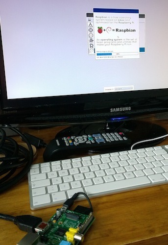
Now, to actually be able to boot up the RasPi, the SD card needs to be loaded with an operating system. This is now very easy, thanks to NOOBS - New Out of Box Software. NOOBS gives the user the possibility to select from a few different OS options. The quick guide covers how to format and install NOOBS onto an SD card. After this, it's time to power on, which is done simply by plugging in the power supply.
Once NOOBS loaded up, I opted to install Raspbian, which is a popular choice. Raspbian is a version of Debian Linux distribution optimized for RasPi's hardware. It includes a graphical user interface instantly familiar to anyone who has used Windows, has drivers for the most common add-ons, and the basic programming tools to get started.
In order to make use of all the good stuff the community has created, it's a good idea to set up networking, as well. For anyone with an Internet-connected Ethernet cable this is a plug & play operation. However, for me a cable wasn't an option, so I tried a few different WiFi options. Since RasPi only has 2 USB ports, I first grabbed a passive 4-port USB hub that was actually part of the "Rock Band" kit for PlayStation 3.
First attempt was with an ancient WiFi 802.11b USB dongle, which Raspbian refused to talk to. I then grabbed an ASUS USB-N13 adapter from my primary computer, which the WiFi Config app was able to use. So, you may not be able to use just any old WiFi adapter with RasPi, but some research may be required.
So, with all this done, I had my hands on a working mini-computer. While that's exciting on its own, it's not the reason I got the RasPi. Next post will be looking at RasPi's capabilities, and my first small project with it.
1 note
·
View note
Text
Ins·Pi·ration
Sometimes, inspiration comes from the strangest of things. This is Sophie the Giraffe.
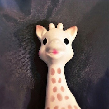
I had been following the Raspberry Pi community from afar, and had cursory knowledge of what was going on around the platform. During this summer, a number of events finally led me to get my hands on a RasPi - a long discussion with a friend & colleague about how to nurture the curiosity and creativity of developers, listening to a fascinating presentation about embedded chipset architecture, and finally, this toy giraffe.
Sitting with this squeaky toy in my hand one day, I had the inane idea that it would be neat to have a programmable robotic arm that could make the toy squeak a melody. The idea stuck with me enough that I started thinking about how to actually carry through with it, adding more ideas like being able to control the device via my smartphone.
RasPi was fresh on my mind from recent conversations, and after a bit of googling I found bits and pieces of the whole, already made and shared by the community. It was then I finally bit the bullet and ordered the Raspberry Pi. I don't hold my original silly idea as a firm design target, but having previously spent time on human-computer interaction, it's refreshing to think about computer-machine and machine-world interactions.
So, a crazy idea put me down this path, and it will be interesting to see where this journey takes me. Next post: getting started with Raspberry Pi.
1 note
·
View note
Link
Short housekeeping note: the contents of this site are licensed under Creative Commons Attribution-NonCommercial 3.0 Unported. (CC BY-NC 3.0) This means is that it's a-ok to use the contents for non-commercial purposes, but if you plan on charging money for derivative works, please ask me for permission first. Thanks. (Link above points to the human-readable license.)
0 notes
Text
Hello World
Hi! A few words about me and this blog.
I've been a PC enthusiast since the early 90's, and online in different ways since then. I've been doing work with software and commercial product development since 1997, but haven't studied or worked directly on design of electronics on a PCB or component level. That said, I've always been curious about digging deeper into the world of electronics, hoping eventually to be able to create something on my own. Previously, though, the entry barrier has seemed somehow insurmountable, mainly due to time management and other lame excuses.
But now, it feels like the Golden Age of making things. There are new, simple & exciting platforms for electronics projects, with an abundance of enthusiasts in the community making cool stuff and contributing back by publishing their designs, tutorials, code, and so on. 3D printing has gone mainstream in the past few years, giving ample opportunities for designers to work their magic. The Internet has provided fertile ground for creativity to blossom, and it's never been easier get started.

That's why I'm finally getting started with my own projects now. Raspberry Pi and Arduino both seem to have a plethora of creative minds hacking away on them, and being great about sharing their work and experiences. I'll be documenting my own progress with both platforms on this blog, with the same intent of giving back to the community; hoping to reach others who are either thinking of or are getting started, and contributing experiences from different stages of the journey.
In the spirit of full disclosure: I am an employee and shareholder of Nokia, but the main driver for setting up this blog is NOT to shill for Nokia and its products. This is my personal project and space for writing about things I'm interested in, and is not associated with my employer nor should anything I say here be interpreted as being representative of Nokia's view on any issue.
Now, onto the real things. Let's make stuff.
--VPK
On Twitter: @vpkivimaki
0 notes