
Don't wanna be here? Send us removal request.
Statistics
We looked inside some of the posts by xonelectronic and here's what we found interesting.
Average Info
Notes Per Post
2
Likes Per Post
2
Reblog Per Post
0
Reply Per Post
0
Time Between Posts
4 days
Number of Posts By Type
Text
8
Last Seen Tumblr Blogs


Fun Fact
Kazakhstan’s Minister of Communications and Informatics has blocked the Tumblr site because it contained 60 sites of terrorism, extremism, and pornography in 2015.
Text
Choosing the Right M24308/25-9F Connectors for Your Specific Robotics and RC Needs
When it comes to robotics and remote control (RC) applications, choosing the right connectors is a critical decision that can significantly impact the performance, reliability, and longevity of your projects. The M24308/25-9F connectors, known for their robustness and reliability, are an excellent choice for many applications. However, selecting the right variant and configuration for your specific needs requires careful consideration. In this blog post, we'll guide you through the key factors to consider when choosing the right M24308/25-9F connectors for your robotics and RC needs.

Understanding M24308/25-9F Connectors
The M24308/25-9F connectors are part of the MIL-DTL-24308 series, designed to meet military standards for durability, performance, and reliability. These connectors typically feature a 9-position layout, making them suitable for applications requiring multiple connections within a compact space.
Key Considerations for Choosing the Right Connector
1. Application Requirements
The first step in choosing the right connector is to understand the specific requirements of your application. Consider the following:
Type of Application: Are you using the connector in an RC car, drone, industrial robot, or another type of system?
Environment: Will the connector be exposed to harsh conditions such as extreme temperatures, moisture, or vibration?
2. Electrical Specifications
Match the connector's electrical specifications to your system's requirements:
Current Rating: Ensure the connector can handle the current levels required by your application.
Voltage Rating: Verify that the connector's voltage rating is suitable for your system.
Contact Resistance: Low contact resistance is crucial for maintaining signal integrity.
3. Mechanical Specifications
Consider the mechanical aspects of the connector:
Size and Weight: Ensure the connector fits within the physical constraints of your design and does not add excessive weight.
Durability: Choose connectors that can withstand the mechanical stresses of your application, such as shocks and vibrations.
4. Connector Materials
The materials used in the connector can impact its performance and longevity:
Contact Materials: High-quality contact materials like gold or silver plating can improve conductivity and resist corrosion.
Housing Materials: Durable housing materials can protect the connector from physical damage and environmental factors.
5. Ease of Installation and Maintenance
Choose connectors that are easy to install and maintain:
Connector Type: Decide between solder-type or crimp-type connectors based on your preference and the tools available.
Accessibility: Ensure the connectors are easily accessible for maintenance and replacement.
6. Compatibility
Ensure the M24308/25-9F connector is compatible with the other components in your system:
Mating Connectors: Verify that the connector mates properly with the corresponding connectors in your design.
Cable Types: Ensure the connector is compatible with the cables you plan to use.
Specific Use Cases and Recommendations
RC Cars
For RC cars, connectors need to withstand vibrations and shocks while ensuring reliable power and signal transmission:
Recommendation: Choose connectors with robust locking mechanisms and vibration-resistant designs. Ensure they can handle the current required by high-performance motors.
Drones
In drones, weight and size are critical, along with the ability to handle environmental factors:
Recommendation: Opt for lightweight connectors with good environmental sealing. Ensure they can handle both power and signal transmission for various drone components.
Industrial Robots
Industrial robots require connectors that can handle high currents and provide reliable connections in harsh environments:
Recommendation: Select connectors with high current ratings and durable construction. Ensure they have good resistance to environmental factors like dust, moisture, and temperature fluctuations.
Autonomous Vehicles
Autonomous vehicles require connectors that can handle multiple signals and power lines with high reliability:
Recommendation: Choose connectors with multiple contact points and high durability. Ensure they provide stable connections even under continuous operation.
Conclusion
Selecting the right M24308/25-9F connectors for your robotics and RC applications involves considering a range of factors, from electrical and mechanical specifications to environmental conditions and ease of installation. By carefully evaluating your specific needs and the characteristics of the available connectors, you can make an informed decision that ensures optimal performance and reliability for your projects.
Investing in high-quality connectors that meet your specific requirements will pay off in the long run by reducing maintenance needs, preventing failures, and enhancing the overall performance of your robotics and RC systems. Choose wisely and enjoy the benefits of reliable, high-performance connections in your next project.
#HighQuality Electronic Components Distributor#Electronic Components Supplier#Electronic Components seller in USA
0 notes
Text
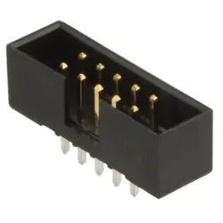
The Evolution of Headers & Wire Housings: From Basic to Advanced Models
Headers and wire housings are fundamental components in the electronics industry, serving as the backbone for connecting various electronic circuits. Over the years, these components have evolved significantly, adapting to the increasing demands for more reliable, efficient, and compact connections. This blog will take you through the journey of headers and wire housings, from their basic origins to the advanced models we see today, such as the LPH-16-S-B/1.
The Early Days: Basic Headers and Wire Housings
In the early days of electronics, headers and wire housings were relatively simple. Basic pin headers and sockets were used to make connections between PCBs (printed circuit boards) and other components. These early connectors were bulky and often lacked the reliability needed for more complex circuits.
Pin Headers: Early pin headers were straightforward, consisting of rows of pins that could be soldered onto a PCB. They provided a simple way to connect wires to a board but were prone to issues like poor contact and corrosion.
Wire Housings: Early wire housings were basic plastic shells that held the wires in place. They were functional but often didn't offer much in terms of protection or ease of use.
The Rise of Reliability: Improved Materials and Designs
As electronic devices became more complex, the need for more reliable and durable connectors grew. This led to significant advancements in the materials and designs of headers and wire housings.
Gold-Plated Contacts: One of the major improvements was the introduction of gold-plated contacts. Gold's excellent conductivity and resistance to corrosion made it an ideal choice for enhancing the reliability of electrical connections.
Enhanced Plastic Materials: The use of high-quality, durable plastics improved the robustness of wire housings, providing better protection against environmental factors and mechanical stress.
Miniaturization and Precision: The Modern Era
The trend towards miniaturization in electronics has had a profound impact on the design of headers and wire housings. As devices became smaller and more integrated, connectors needed to follow suit.
Surface-Mount Technology (SMT): The advent of SMT allowed for much smaller and more precise connectors. SMT headers could be mounted directly onto the surface of PCBs, reducing space requirements and improving performance.
High-Density Connectors: Modern headers and wire housings, like the LPH-16-S-B/1, are designed to support high-density connections, making them ideal for applications where space is at a premium.
Advanced Models: LPH-16-S-B/1 and Beyond
Today, headers and wire housings are more advanced than ever, with models like the LPH-16-S-B/1 showcasing the pinnacle of connector technology.
LPH-16-S-B/1 Features: This model boasts a range of features that make it suitable for high-performance applications. It includes gold-plated contacts for excellent conductivity, robust plastic housing for durability, and a compact design that supports high-density connections.
Versatility and Application: The LPH-16-S-B/1 is versatile and can be used in a variety of applications, from consumer electronics to industrial machinery. Its design ensures reliable connections in even the most demanding environments.
The Future of Headers and Wire Housings
As technology continues to evolve, so too will headers and wire housings. Future advancements may include further miniaturization, improved materials for even greater durability, and enhanced designs for easier integration and use.
Smart Connectors: The integration of smart technology into connectors could provide real-time diagnostics and monitoring, further improving the reliability and performance of electronic systems.
Eco-Friendly Materials: With a growing focus on sustainability, future connectors may utilize more eco-friendly materials without compromising on performance.
Conclusion
The evolution of headers and wire housings from basic models to advanced designs like the LPH-16-S-B/1 highlights the significant strides made in connector technology. As electronics continue to advance, these components will remain crucial in ensuring reliable, efficient, and compact connections. By understanding their history and advancements, we can better appreciate the critical role they play in modern electronic devices.
0 notes
Text
How to Set Up and Configure the A4988 Stepper Motor Driver
The A4988 Stepper Motor Driver Carrier Black is a versatile and widely-used driver for controlling bipolar stepper motors. Setting up and configuring the A4988 correctly is crucial to ensure optimal performance and prevent damage to your motor and driver. This article provides a comprehensive guide on how to set up and configure the A4988 Stepper Motor Driver.

1. Unboxing and Initial Inspection
Before you begin, ensure that you have all the necessary components:
A4988 Stepper Motor Driver Carrier Black
Stepper motor
Power supply (typically 8V to 35V)
Microcontroller (e.g., Arduino)
Breadboard and connecting wires
Inspect all components for any visible damage.
2. Wiring the A4988 Stepper Motor Driver
Proper wiring is crucial for the safe operation of the A4988. Follow these steps:
Connect the Motor:
Connect the stepper motor coils to the A4988’s output pins (2A, 2B, 1A, 1B). Ensure the connections are correct to avoid damaging the motor driver.
Connect Power Supply:
Connect the motor power supply (8V to 35V) to the VDD and GND pins of the A4988. Ensure the power supply can deliver sufficient current for your motor.
Connect Microcontroller:
Connect the step, direction, enable, and ground pins of the A4988 to the corresponding pins on your microcontroller. Typically, these connections are:
STEP pin to a digital output pin on the microcontroller
DIR pin to another digital output pin
ENABLE pin to ground (or a digital output pin if you want to control it)
Optional Connections:
You may also connect the MS1, MS2, and MS3 pins to configure microstepping settings. These can be connected to logic high (5V) or low (GND) according to your desired microstepping mode.
3. Configuring Current Limit
Setting the correct current limit is vital to prevent overheating and ensure smooth motor operation. Follow these steps to configure the current limit:
Adjust the Potentiometer:
Locate the small potentiometer on the A4988 board. This potentiometer adjusts the current limit.
Use a small screwdriver to turn the potentiometer. Turning it clockwise increases the current limit, while turning it counterclockwise decreases it.
Measure VREF:
To set the current limit accurately, measure the VREF voltage with a multimeter. Place the positive probe on the potentiometer’s test point and the negative probe on a ground pin.
Calculate Current Limit:
The formula for setting the current limit is: Current Limit = VREF / (8 * R_SENSE), where R_SENSE is the current sense resistor value (typically 0.05 ohms).
Adjust the potentiometer until the desired VREF voltage is reached.
4. Setting Microstepping Mode
The A4988 supports various microstepping modes, which can be set by configuring the MS1, MS2, and MS3 pins:
Microstepping Table:
Full step: MS1 = 0, MS2 = 0, MS3 = 0
Half step: MS1 = 1, MS2 = 0, MS3 = 0
Quarter step: MS1 = 0, MS2 = 1, MS3 = 0
Eighth step: MS1 = 1, MS2 = 1, MS3 = 0
Sixteenth step: MS1 = 1, MS2 = 1, MS3 = 1
Connecting MS Pins:
Connect the MS1, MS2, and MS3 pins to logic high (5V) or logic low (GND) according to the desired microstepping mode.
5. Programming the Microcontroller
To control the A4988, you’ll need to write a program for your microcontroller. Upload the code to your Arduino. Adjust the delay Microseconds value to control the speed of the stepper motor.
6. Testing and Fine-Tuning
Once everything is connected and configured, it’s time to test your setup:
Power On:
Turn on your power supply and microcontroller.
Initial Test:
Run the microcontroller program to ensure the motor steps as expected.
Adjustments:
Fine-tune the current limit and microstepping settings if necessary.
Monitoring:
Monitor the motor and driver for any signs of overheating or unexpected behavior.
Conclusion
Setting up and configuring the A4988 Stepper Motor Driver Carrier Black requires careful attention to wiring, current limiting, and microstepping settings. By following this guide, you can ensure your stepper motor operates efficiently and reliably, making the most of the A4988’s capabilities. Happy tinkering!
0 notes
Text
Understanding the Technical Specifications of SMBJ70CA-TR TVS Diodes
TVS (Transient Voltage Suppression) diodes, such as the SMBJ70CA-TR, play a crucial role in protecting electronic circuits from voltage spikes and electrostatic discharge (ESD). Understanding their technical specifications is essential for selecting the right component for your application. Let's dive into the key specifications of the SMBJ70CA-TR TVS diode and what they mean for your projects.

1. Breakdown Voltage (V_BR)
The breakdown voltage is the voltage at which the diode starts to conduct in reverse. For the SMBJ70CA-TR, the breakdown voltage range is typically between 77.8V and 95.7V. This means that when the voltage exceeds this range, the diode will begin to conduct, clamping the voltage to a safe level and protecting the circuit.
2. Stand-off Voltage (V_R)
The stand-off voltage is the maximum voltage that can be applied to the diode without it conducting. For the SMBJ70CA-TR, the stand-off voltage is 70V. This is the normal operating voltage below which the diode remains inactive. It’s crucial to ensure that the operating voltage of your circuit does not exceed this value.
3. Peak Pulse Current (I_PP)
The peak pulse current is the maximum current the diode can handle during a transient event. The SMBJ70CA-TR can withstand a peak pulse current of 1.3A (10/1000µs waveform). This parameter is vital for understanding the diode’s capacity to handle sudden surges and is a key factor in ensuring the protection of your circuit.
4. Clamping Voltage (V_C)
The clamping voltage is the voltage to which the diode clamps the transient event. For the SMBJ70CA-TR, the clamping voltage is 113V at a peak pulse current of 1.3A. This value indicates the maximum voltage your circuit will experience during a transient event, ensuring it remains within safe limits.
5. Power Dissipation (P_PP)
Power dissipation is the maximum power the diode can dissipate. The SMBJ70CA-TR has a peak pulse power dissipation of 600W (10/1000µs waveform). This parameter helps determine the diode’s ability to handle power surges without being damaged.
6. Response Time
The response time of a TVS diode is the time it takes to respond to a transient event. The SMBJ70CA-TR has a response time of less than 1 picosecond. This ultra-fast response ensures immediate protection for sensitive electronic components from voltage spikes.
7. Capacitance
The capacitance of a TVS diode affects the signal integrity in high-speed circuits. For the SMBJ70CA-TR, the capacitance is typically 150pF at 1MHz. Lower capacitance is preferred for high-frequency applications to avoid signal degradation.
8. Packaging
The SMBJ70CA-TR is packaged in an SMB (DO-214AA) package. This surface-mount package is suitable for automated assembly processes and offers a compact form factor for space-constrained applications.
9. Polarity
The SMBJ70CA-TR is a bidirectional TVS diode. This means it can protect against both positive and negative voltage transients, making it versatile for various applications where bidirectional protection is required.
10. Operating and Storage Temperature Range
The operating temperature range for the SMBJ70CA-TR is from -55°C to +150°C, and the storage temperature range is also -55°C to +150°C. This wide temperature range ensures reliable performance in diverse environmental conditions.
11. Qualification and Compliance
The SMBJ70CA-TR TVS diode complies with industry standards and qualifications, ensuring high reliability and performance. It meets the requirements of IEC 61000-4-2 (ESD) and IEC 61000-4-4 (EFT) standards, making it suitable for robust ESD and surge protection.
Conclusion
Understanding the technical specifications of the SMBJ70CA-TR TVS diode is crucial for ensuring the protection and reliability of your electronic circuits. By carefully considering parameters such as breakdown voltage, stand-off voltage, peak pulse current, clamping voltage, power dissipation, and response time, you can select the right TVS diode for your application. Additionally, factors like capacitance, packaging, polarity, and temperature range are important to ensure optimal performance and compatibility with your design requirements.
0 notes
Text
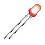
HLMP-3850A Standard LEDs vs. SMD LEDs: Which is Better for Your Projects?
When it comes to choosing the right type of LED for your project, the decision often boils down to two main options: through-hole LEDs like the HLMP-3850A Standard LEDs, and Surface-Mount Device (SMD) LEDs. Each type has its own unique advantages and disadvantages, making them suitable for different applications. In this blog, we'll explore the key differences between HLMP-3850A Standard LEDs and SMD LEDs to help you decide which is better for your specific needs.
Understanding HLMP-3850A Standard LEDs
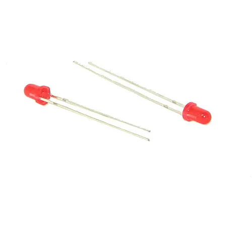
Through-hole LEDs are a classic choice in LED technology. The HLMP-3850A is a prime example of this type, characterized by its two long metal leads that pass through the PCB (Printed Circuit Board) and are soldered on the other side. Here are some key features:
Durability and Reliability: Through-hole LEDs like the HLMP-3850A are known for their robust construction, making them highly durable and reliable. This makes them suitable for applications where long-term reliability is critical.
Ease of Installation: The leads of through-hole LEDs can be easily inserted and soldered into a PCB, making them relatively straightforward to install, especially for DIY enthusiasts and small-scale projects.
Mechanical Stability: The mechanical bond created by the leads passing through the PCB adds to the stability of the connection, reducing the risk of damage from mechanical stress or vibration.
Visibility: Through-hole LEDs often provide better visibility due to their size and positioning above the surface of the PCB, making them ideal for indicator lights and displays.
Understanding SMD LEDs
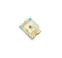
SMD LEDs are a more modern development in LED technology, designed for surface mounting directly onto the PCB. They are characterized by their small size and lack of leads that pass through the board. Key features of SMD LEDs include:
Compact Size: SMD LEDs are much smaller than through-hole LEDs, allowing for more compact and densely packed circuit designs. This is essential for modern electronics where space is at a premium.
Higher Efficiency: Due to their design, SMD LEDs often provide higher luminous efficiency, meaning they can produce more light per unit of power consumed compared to through-hole LEDs.
Versatility: SMD LEDs can be easily integrated into automated assembly processes, making them ideal for large-scale production and complex circuit designs.
Heat Dissipation: The design of SMD LEDs allows for better heat dissipation, which can enhance the performance and lifespan of the LEDs.
Comparing HLMP-3850A Standard LEDs and SMD LEDs
1. Application Suitability
HLMP-3850A Standard LEDs: Ideal for applications where visibility, mechanical stability, and ease of installation are critical. Common uses include indicator lights, displays, and situations where manual soldering is preferred.
SMD LEDs: Best suited for compact, high-density circuit designs and automated assembly processes. Common in consumer electronics, automotive lighting, and anywhere space is limited.
2. Installation and Assembly
HLMP-3850A Standard LEDs: Easier to install manually due to their leads. Suitable for prototyping, hobbyist projects, and small-scale production.
SMD LEDs: Requires precise placement and often automated assembly. Ideal for large-scale production and professional manufacturing environments.
3. Performance and Efficiency
HLMP-3850A Standard LEDs: Reliable with moderate efficiency. Good for applications where power consumption is not the primary concern.
SMD LEDs: Higher efficiency and better heat dissipation. Suitable for energy-efficient applications and high-performance lighting.
4. Size and Design Constraints
HLMP-3850A Standard LEDs: Larger size may be a constraint in compact designs. However, their visibility can be an advantage in certain applications.
SMD LEDs: Compact and versatile, allowing for innovative and space-saving designs. Ideal for modern electronics and portable devices.
Conclusion: Which is Better for Your Project?
The choice between HLMP-3850A Standard LEDs and SMD LEDs ultimately depends on the specific requirements of your project. If you prioritize ease of installation, mechanical stability, and visibility, through-hole LEDs like the HLMP-3850A are an excellent choice. On the other hand, if your project demands compact design, higher efficiency, and integration into automated assembly, SMD LEDs are likely the better option.
Consider the nature of your application, the available space, and the production scale when making your decision. Both types of LEDs have their strengths, and understanding these can help you make an informed choice that enhances the success of your project.
more information here -
0 notes
Text
How to Source Genuine R15Z104M1HL2-B Capacitors in the USA

In the fast-paced world of electronics, ensuring that you have reliable components is crucial for the success and longevity of your projects. Multilayer Ceramic Capacitors (MLCCs), such as the R15Z104M1HL2-B, are fundamental components widely used in various applications due to their high capacitance, stability, and reliability. However, sourcing genuine R15Z104M1HL2-B capacitors can be challenging given the proliferation of counterfeit parts in the market. Here’s a comprehensive guide to help you source genuine R15Z104M1HL2-B capacitors in the USA.
1. Purchase from Authorized Distributors
One of the most reliable ways to ensure you are getting genuine R15Z104M1HL2-B capacitors is to buy from authorized distributors. These distributors have direct relationships with manufacturers and are more likely to provide authentic components. Here are some well-known authorized distributors in the USA:
Digi-Key Electronics
Mouser Electronics
Arrow Electronics
Avnet
These distributors not only guarantee authenticity but also offer comprehensive support and return policies.
2. Verify the Distributor's Authorization
Before making a purchase, verify that the distributor is authorized by the manufacturer. This information is usually available on the manufacturer's official website. Look for a list of authorized distributors and cross-check to ensure the distributor you are considering is listed.
3. Check for Proper Documentation
Authentic distributors will provide proper documentation with your purchase. This includes:
Certificate of Authenticity
Manufacturer’s Datasheet
RoHS Compliance Certificate
These documents confirm that the capacitors meet the necessary quality and regulatory standards.
4. Examine the Packaging and Labeling
Genuine R15Z104M1HL2-B capacitors will have consistent and professional packaging. Look for the following:
Manufacturer’s Logo
Part Number
Date Code
Lot Number
Inconsistent or poor-quality packaging can be a red flag for counterfeit products.
5. Use Trusted Online Marketplaces
If you prefer purchasing online, use trusted marketplaces that have stringent verification processes. Platforms like Amazon and eBay can be reliable if you ensure the seller has a high rating and positive feedback specifically for electronic components.
6. Engage with Industry Forums and Communities
Joining industry forums and communities can provide insights into where others are sourcing their components. Websites like Weblog and the Electronics Stack Exchange have active communities where professionals discuss their experiences with various distributors and sellers.
7. Conduct a Physical Inspection
Once you receive the capacitors, conduct a physical inspection:
Check the Capacitance Value: Use a capacitance meter to verify the actual capacitance against the specified value.
Inspect for Physical Defects: Look for any signs of tampering, unusual markings, or physical damage.
8. Leverage Professional Testing Services
For high-volume purchases or critical applications, consider using professional testing services. These services can perform detailed analyses to confirm the authenticity of your components. Companies like Integra Technologies and White Horse Laboratories offer such services.
9. Stay Informed about Counterfeit Risks
Stay updated on the latest trends and reports regarding counterfeit electronic components. Organizations such as the Electronic Components Industry Association (ECIA) and the Independent Distributors of Electronics Association (IDEA) provide valuable resources and updates on counterfeit risks.
10. Establish Direct Relationships
For long-term needs, consider establishing direct relationships with manufacturers or their authorized distributors. This not only ensures a steady supply of genuine parts but also may offer better pricing and priority service.
Conclusion
Sourcing genuine R15Z104M1HL2-B capacitors in the USA requires diligence and careful consideration. By purchasing from authorized distributors, verifying documentation, checking packaging, and staying informed, you can significantly reduce the risk of obtaining counterfeit components. Ensuring the authenticity of your capacitors will lead to more reliable and successful electronic projects. Always prioritize quality and reliability over cost to maintain the integrity of your work.
By following these guidelines, you can confidently source genuine R15Z104M1HL2-B capacitors and ensure your electronic designs perform at their best.
0 notes
Text
CR25-10K Carbon Composition Resistors seller & distributer in USA
We are the renowned CR25-10K Carbon Composition Resistors seller and distributor in the USA, India, Europe, Australia, and beyond. CR25-10K Carbon Composition Resistors is a manufacturer from Netech. X-ON Electronics Components provides affordable electronic Carbon Composition Resistors in the USA.
#HighQuality Electronic Components Distributor#Electronic Components Supplier#Electronic Components seller in USA
0 notes
Text
2EHDVC-02P Pluggable Terminal Blocks seller & distributer in USA

We are the renowned 2EHDVC-02P Pluggable Terminal Blocks seller and distributor in the USA, India, Europe, Australia, and beyond. 2EHDVC-02P Pluggable Terminal Blocks is a manufacturer from Dinkle. X-ON Electronics Components provides affordable electronic Pluggable Terminal Blocks in the USA.
#HighQuality Electronic Components Distributor#Electronic Components Supplier#Electronic Components seller in USA
2 notes
·
View notes