#Overmolded Cable
Explore tagged Tumblr posts
Visit Tumblr Blog
Explore Tumblr blogs with no restrictions, modern design and the best experience.
Last Seen Tumblr Blogs


Fun Fact
BuzzFeed published a report claiming that Tumblr was utilized as a distribution channel for Russian agents to influence American voting habits during the 2016 presidential election in Feb 2018.
Text
What Is Overmolding Injection Molding ? Explained
Overmolding Injection Molding that mixes or greater substances proper right into a single, unified difficulty. This advanced production technique is notably used to decorate product capability, aesthetics, and customer comfort. Overmolding consists of molding a layer of cloth (commonly a smooth plastic or rubber-like material) over a formerly molded inflexible base problem (called the substrate). The give up result is an extended lasting, multi-cloth component with progressed houses.
The Overmolding Process
The Overmolding Injection Molding Manufacturer in China approach usually starts off evolving with the arrival of a base factor, the usage of conventional injection molding. This substrate can be crafted from several substances, together with ABS, polycarbonate, or nylon. After the base detail is molded and cooled, it is positioned into a 2d mold in which the overmold material—commonly thermoplastic elastomers (TPE) or silicone—is injected over or spherical it.
There Are Number One Sorts Of Overmolding:
Insert Molding – The substrate is manually or automatically inserted into the mold earlier than overmolding.
Two-Shot Molding – Two materials are injected in separate ranges using a single device in an unbroken, computerized system.
Benefits of Overmolding
Overmolding Injection Molding offers several key blessings that make it a famous desire in industries like vehicles, client electronics, medical devices, and household items.
Improved Ergonomics- Overmolding clean substances over hard plastics complements grip, comfort, and price. For instance, device handles and toothbrushes regularly function rubberized grips made through overmolding.
Aesthetic Appeal- Overmolding permits for the advent of elegant, multi-colored parts with particular textures and finishes, enhancing the product’s look and sense.
Shock and Vibration Resistance- The mild outer layer can soak up impact, making overmolded factors exceptional for protecting device, electronics casings, and clinical tools.
Water and Chemical Resistance- Overmolding can seal joints and gaps, imparting safety in opposition to moisture and merciless chemicals.
Cost Efficiency- By combining more than one material proper right into an unmarried production cycle, overmolding can reduce assembly steps, decrease hard paintings expenses, and decorate widespread manufacturing overall performance.
Applications of Overmolding
Overmolding Injection Molding Is Significantly Used During Various Sectors:
Consumer Electronics: Creating durable, surprise-resistant mobile phone cases and cable connectors.
Automotive Industry: Producing dashboard components, knobs, and climate-resistant seals.
Medical Devices: Manufacturing ergonomic and sterile surgical devices with greater suitable grip.
Power Tools: Crafting rugged, non-slip handles for drills and one-of-a-kind tools.
Household Products: Enhancing products like kitchen utensils and personal care gadgets.
Conclusion
Overmolding Injection Molding in China is an effective method that elevates product format and functionality. By integrating specific substances right into a single detail, manufacturers can supply higher man or woman reviews, progressed durability, and higher aesthetic value—making overmolding a key innovation in modern plastic production.
#Overmolding Injection Molding#Overmolding Injection Molding in China#Overmolding Injection Molding China#Overmolding
0 notes
Text
0 notes
Text
0 notes
Text
So the IEC power cord i use to plug in my Eurorack system is probably overkill for the application. It's got one of those big, chunky, overmolded hospital grade plugs and the cable itself is noticably thicker than that found in your usual run of computer power cords. The right-angle IEC connector plug* is similarly sturdy, with a molded note that it's rated for 13A at 125V; it's feeding two ±12V supplies that deliver an amp on each rail, allowing for a great deal of loss in the transformers or whatever that's still over a thousand watts of excess capacity.
But anyway, I somehow hadn't yet taken a close look at the little printed flag near the connector. It's got what looks like a UPC barcode on one side, presumably the product identifier, but on the other is a warning:

... with the consequences so undefined, I'm just going to make sure to insert it securely.
* Strictly speaking, it's IEC 60320 C13? The spec, renumbered from 1970's IEC 320 in 1994, includes six different plug/jack shapes, including the C1/C2 "figure 8" and C3/C4 "Mickey mouse" connectors, but C13/C14 are the computer power supply ones that everybody calls IEC.
0 notes
Text
Why Choose Overmolded Cable Assemblies?
✔ Super Strength: Protects against shock, moisture, and harsh environments.
✔ Bending Benefits: Prevents flex and pull damage.
✔ Sealed Tight: Blocks dust and moisture.
✔ Longer Lifespan: Safeguards connections.
✔ Strain Relief & Aesthetics: Durable, clean, and customizable.
Enhance durability and reliability with overmolded cable assemblies.
Contact us today!
Reach out to us @ https://www.violintec.com/best-cable-wireharness-company/

0 notes
Text
Cable Assembly Market to Reach $299.2 Billion by 2031: Key Industry Players and Growth Drivers
The cable assembly market is projected to hit $299.2 billion by 2031, growing at a compound annual growth rate (CAGR) of 6.3% from 2024 to 2031. A cable assembly consists of wires and cables bundled into a single unit, enabling the connection of various systems and equipment for manufacturing components and finished products. These assemblies play a critical role across a wide range of industries, including automotive, telecommunications, aerospace, industrial, medical, and consumer electronics. The market's growth is being driven by factors such as the rising adoption of electric vehicles (EVs), increased demand from the aerospace sector, and growing internet penetration worldwide. Download Research Report Sample @ https://www.meticulousresearch.com/download-sample-report/cp_id=4975?utm_source=blog&utm_medium=social&utm_campaign=product&utm_term=17-10-2024 Key Market Players Amphenol DC Electronics Founded in 1979 and headquartered in San Jose, California, Amphenol DC Electronics specializes in designing and manufacturing electrical, electronic, and fiber optic connectors, as well as custom wire harnesses and cable assemblies. Serving industries like aerospace, defense, industrial, agriculture, and medical, the company’s product offerings include ruggedized cable assemblies, smart cables, and custom overmold interconnects. With manufacturing facilities in Silicon Valley and Nogales, Mexico, the company operates globally, reaching North America, Europe, Asia-Pacific, the Middle East, Africa, and Latin America. TE Connectivity Ltd. Established in 2007 and based in Pennsylvania, U.S., TE Connectivity provides advanced connectivity and sensor solutions for industries such as transportation, medical, and data communication. Their diverse product range includes antennas, cable assemblies, connectors, EMI filters, and sensors. The company operates over 100 manufacturing and engineering centers globally, with a presence in North America, Europe, Asia-Pacific, the Middle East, Africa, and Latin America. JAE Electronics, Inc. Founded in 1953 and headquartered in Tokyo, Japan, JAE Electronics designs and manufactures connectors and aerospace products. Their products include board-to-board, board-to-cable, and fiber optic connectors, as well as waterproof electrical connectors. Serving industries such as smartphones, transportation, and medical, JAE Electronics operates across North America, Europe, and Asia-Pacific. Luxshare Precision Industry Co., Ltd. Founded in 2004 in Dongguan, China, Luxshare Precision specializes in designing and manufacturing cable assemblies and connector system solutions. Their product range includes antennas, micro coaxial cables, flexible flat cables, and precision components, serving industries like consumer electronics, automotive, and cloud computing. Luxshare has a global presence across North America, Europe, Asia-Pacific, Latin America, and the Middle East and Africa. Koch Industries, Inc. (Molex LLC) Headquartered in Wichita, Kansas, Koch Industries operates across a variety of sectors including electronics, chemicals, and refining. Molex LLC, a subsidiary of Koch Industries, provides electronic solutions such as cable assemblies for industries like automotive, data communication, and medical. Koch Industries has a vast geographic presence in over 60 countries across North America, Europe, Asia-Pacific, Latin America, and the Middle East and Africa. Browse in depth @ https://www.meticulousresearch.com/product/cable-assembly-market-4975?utm_source=blog&utm_medium=social&utm_campaign=product&utm_term=17-10-2024
0 notes
Text
Get Arduino Atmega 2560 R3 Board at Affordable Price in Ainow

With the MAX3421e IC, the Mega 2560 Atmega2560-16au compatible with Arduino is a microcontroller board based on the Arduino Atmega 2560 R3.
With a total of 54 digital input/output pins (including 15 PWM outputs), 16 analog inputs, and 4 UARTs, the MEGA ADK is jam-packed with features. It also boasts a 16 MHz crystal oscillator and comes equipped with a USB connection, power jack, ICSP header, and reset button. Based on the Arduino Atmega 2560 r3, this board shares many similarities with its counterparts, including the ATmega8U2 program that serves as a USB-to-serial converter. In fact, the Mega ADK revision 3 even includes a resistor that conveniently pulls the 8U2 HWB line to ground for easier DFU(Device Firmware Upgrade) mode access.
New features on the board include:
As part of the 1.0 pin-out, the shields will be able to adjust to the voltage provided by the board by adding SDA and SCL pins near the AREF pin and two new pins near the RESET pin, the IOREF. Shields in the future will be compatible with boards that use AVR, which operate at 5V, and Arduino Due, which operates at 3.3V. The second pin, which is not connected, will be used for future purposes.
Circuit with a stronger RESET.
A USB connection or an external power supply can be used to power the Arduino Atmega 2560 R3 Android Accessory Development Kit (ADK). An AC-to-DC adapter (wall-wart) or battery can be used to supply external (non-USB) power. An adapter can be connected by plugging a 2.1mm center-positive plug into the board’s power jack.
GND and Vin pin headers on the POWER connector can be inserted with battery leads. Since the Mega R3 Android Accessory Development Kit (ADK) is a USB Host, the phone will attempt to draw power from it when it needs to charge. When the ADK is powered over USB, 500mA is available for the phone and board.
Features and specifications:
Arduino Atmega 2560 r3 :
Atmel is the programmer
Microcontroller ATmega2560.
A total of 54 digital input/output terminals (14 of which have programmable PWM outputs) are available.
There are 16 analog inputs.
There are four UARTs (hardware serial ports).
A crystal clock with a frequency of -16 MHz.
A bootloader allows sketches to be downloaded via USB without having to go through an external writer.
-Powered by USB or external power supply (not supplied). The device will automatically switch between power sources.
A heavy gold plate construction is used.
The clock speed is 16 MHZ.
Bootloader uses 8 KB of the 256 KB flash memory.
The operating voltage is 6 x 12 volts.
Mega 2560 Arduino cable:
It is hot pluggable.
-Compatible with PCs.
Strain relief and PVC overmolding ensure error-free data transmissions for a lifetime.
-Aluminum under-mold shield helps meet FCC requirements for KMI/RFI interference.
-Filled and braided shield conforms to fully rated cable specifications and reduces EMI/FRI interference.
Error-free, high-performance transmission.
Case made of transparent acrylic:
MEGA2560 R3 (unassembled) compatible.
It is possible to adjust the cover.
Transparent color.
Acrylic is the material used.
The power of
The external power regulator has a maximum capacity of 1500mA. Of this, 750mA is reserved for the phone and MEGA ADK board, while the remaining 750mA is dedicated to any attached actuators and sensors. To use this amount of current, a power supply must be able to provide at least 1.5A. While the board can run on an external supply ranging from 5.5 to 16 volts, it is recommended to use between 7 and 12 volts. If supplied with less than 7V, there may be insufficient voltage output from the 5V pin, potentially causing instability in the board. On the other hand, using more than 12V may result in overheating of the voltage regulator and potential damage to the board components.
What follows is:
This pin is used to supply voltage to the Arduino board when it is powered by an external power source rather than 5 volts from the USB connection or another regulated source.
This pin generates a regulated 5V from the board’s regulator. The board can be powered via the DC power jack (7-12V), USB connector (5V), or VIN pin (7-12V). If you supply voltage via the 5V or 3.3V pins, you bypass the regulator and can damage your board. Please do not do so.
The onboard regulator generates 3.3 volts. Maximum current draw is 50 milliamps.
The ground pins are GND.
The Arduino board’s IOREF pin serves as a voltage reference for the microcontroller. In a properly configured shield, you can determine the voltage of the IOREF pin and select an appropriate power source or enable voltage translators to work with either 5V or 3.3V outputs.
The memory
It has 256 KB of flash memory for storing code (of which 8 KB is used for the bootloader), 8 KB of SRAM, and 4 KB of EEPROM (which can be read and written).
The inputs and outputs
By using pin Mode(), digital Write(), and digital Read() functions, each of the Arduino Atmega 2560 R3 Android Accessory Development Kit (ADK)’s 50 digital pins can be used as inputs or outputs. There is an internal pull-up resistor of 20-50 Ohm on each pin. They operate at 5 volts. They can provide or receive a maximum current of 40 mA. Some of the pins have specialized functions:
Serial 0: 0 (RX) and 1 (TX), Serial 1: 19 (RX) and 18 (TX), Serial 2: 17 (RX) and 16 (TX), Serial 3: 15 (RX) and 14 (TX). Connected to the ATmega8U2 USB-to-TTL Serial chip on pins 0 and 1.
External Interrupts: 2 (interrupt 0), 3 (interrupt 1), 18 (interrupt 5), 19 (interrupt 4), 20 (interrupt 3), and 21 (interrupt 2). An interrupt can be triggered on a low value, a rising or falling edge, or a change in value using the attach Interrupt() function.
Providing 8-bit PWM output with the analog Write() function for PWM values 2 to 13 and 44 to 46.
SPI: 50 (MISO), 51 (MOSI), 52 (SCK), 53 (SS). These pins support SPI communication using the SPI library. They are also broken out on the ICSP header, which is physically compatible with Uno, Duemilanove, and Diecimila.
MAX3421E is the USB host.
The Max3421E
The following pins are used to communicate with Arduino via the SPI bus:
Seven (RST), fifty (MISO), fifty one (MOSI), and fifty two (SCK) are digital.
You should not use Digital pin 7 for inputs or outputs because it is used to communicate with MAX3421E
PJ3 (GP_MAX), PJ6 (INT_MAX), PH7 (SS) are not broken out on headers.
A built-in LED is connected to digital pin 13. When the pin is HIGH, the LED is on, when it is LOW, it is off.
Supports TWI communication using the Wire library. These pins are not in the same location as the Duemilanove or Diecimila TWI pins.
Android Accessory Development Kit (ADK) with Arduino Atmega 2560 R3 has 16 analog inputs, each with a resolution of 10 bits (i.e. 1024 different values). It is possible to change the upper end of the range of the pins by using the AREF pin and analog Reference() function. Other pins on the board include:
Reference voltage for analog inputs. Use with analog reference.
Reset. This line is typically used to add a reset button to shields which block the board’s reset button.
The communication process
The Arduino Atmega 2560 R3 Android Accessory Development Kit (ADK) offers various communication options, including connecting with a computer, another Arduino, or other micro-controllers. The ATmega2560 has four hardware UARTs for TTL (5V) serial communication. Additionally, the board has an ATmega8U2 that uses USB to provide a virtual com port for computer software. For Windows machines, a .inf file may be needed but OSX and Linux machines will automatically detect the board as a COM port. In the Arduino software, there is a serial monitor feature for sending and receiving simple textual data from the board.
When data is transmitted via the ATmega8U2/16U2 chip and USB connection to the computer (but not for serial communication on pins 0 and 1), the board’s RX and TX LEDs flash. Any of the MEGA ADK’s digital pins can be serialized with a software-serial library. TWI and SPI communication are also supported by the ATmega2560. The Arduino software contains a Wire library to simplify TWI communication, see Wire library for details. For SPI communication, use the SPI library.
The USB host interface given by MAX3421E IC allows Arduino MEGA ADK to connect and interact with any type of device with a USB port. It allows you to interact with many types of phones, control Canon cameras, and interface with keyboards, mice, and gaming controllers such as Wiimote and PlayStation 3.
The programming language
For details, see the reference and tutorials. You can program the Mega R3 Android Accessory Development Kit (ADK) with Arduino software (download). You don’t need an external hardware programmer to upload new code to the ATmega2560 on the MEGA ADK since it comes preburned with a boot-loader (just like the Arduino Atmega 2560 r3). The STK500v2 protocol (references and C header files) is used for communication.
You can also bypass the bootloader and program the microcontroller through the ICSP (In-Circuit Serial Programming) header using Arduino ISP or similar; see these instructions for details. Atmega8U2 firmware source code is available in the Arduino repository. An ATmega8U2 is loaded with a DFU bootloader, which can be activated by:
The Rev1 boards have the following features:
Resetting the 8U2 requires connecting the solder jumper on the back of the board (near the map of Italy).
Rev2 and later boards have a resistor pulling the 8U2/16U2 HWB line to ground, making it easier to put into DFU mode. To load a new firmware, you can use the FLIP software (Windows) or the DFU programmer (Mac OS X and Linux). If you prefer, you can use the ISP header with an external programmer (overwriting the DFU bootloader). See this user-contributed tutorial for more information.
Reset (automatic) software
The Arduino Atmega 2560 r3 ADK has been designed to reset by software from a connected computer instead of requiring a physical press of the reset button before an upload. This is achieved by connecting one of the hardware flow control lines (DTR) of the ATmega8U2 to the reset line of the ATmega2560 through a 100 nano-farad capacitor. Whenever this line is asserted, causing it to drop low, the chip will be reset momentarily. The upload button in the Arduino environment makes use of this feature, enabling you to easily upload code without needing to manually press the reset button.
As a result, the boot-loader’s timeout can be reduced since DTR can be synchronized with the upload initiation. This arrangement also has additional effects when the MEGA ADK is linked to a computer running Mac OS X or Linux. Upon being connected to software via USB, the board resets and enters bootloader mode for about half a second. During this time, any non-code data will be disregarded by the programmed bootloader, but it will capture the first few bytes of data transmitted after the connection is established.
Ensure that the software your sketch is communicating with allows for a brief pause after establishing the connection before sending any initial data. The MEGA ADK has a trace that can be removed to disable the auto-reset function. Connect the pads on either side of the trace to re-enable it, labeled as RESET-EN. Alternatively, you can disable the auto-reset by connecting a 110-ohm resistor from 5V to the reset line; additional information can be found in this forum thread.
Over-current protection for USB devices
A resettable polyfuse protects your computer’s USB ports from shorts and overcurrents with the Arduino Atmega 2560 R3 Android Accessory Development Kit (ADK). In spite of the fact that most computers have their own internal protection, a fuse provides an additional layer of protection. When more than 500 mA is applied to the USB port, the fuse automatically stops the connection.
Shield compatibility and physical characteristics
The Mega R3 Android Accessory Development Kit (ADK) PCB has a maximum length and width of 4 inches and 2.1 inches respectively. The USB connector and power jack extend beyond the length, while three screw holes are available for surface or case attachment. It is important to note that the distance between digital pins 7 and 8 is 160 mil, which is not an even multiple of the standard 100 mil spacing for the other pins. Additionally, the MEGA ADK can be used with most shields designed for the Uno, Diecimila or Duemilanove boards.
The digital pins 0 to 13 (as well as the adjacent AREF and GND pins), analog inputs 0 to 5, the power header, and the ICSP header are all positioned in the same spot. In addition, the main UART (serial port) is located on the same pins (0 and 1); as are external interrupts 0 and 1 (pins 2 and 3). SPI is also available through the ICSP header on the MEGA ADK and Duemilanove / Diecimila.
On the MEGA ADK (20 and 21), I2C and D are not located on the same pins.
1 note
·
View note
Text
What Should You Know about Thermoforming Materials?
Thermoforming is a common plastic manufacturing process method, also known as vacuum forming or pressure forming. The thermoforming process is to heating plastic sheets to a softened state, then use negative air pressure to attract the plastic sheet to the surface of the mold, and use cooling to solidify it to form.
There are several thermoforming methods used in actual production, and the most basic ones are six: differential pressure forming, overmolding, plunger-assisted molding, suction molding, countermolding, and twin sheet forming.
Thermoforming is widely used in the manufacture of various plastic products, such as packaging boxes, toys, medical equipment, automotive interior parts, etc.
Thermoforming materials usually use thermoplastic plastics. The only raw materials are plastic sheets. Commonly used sheets include: PVC, PET, PP, PS, PET-G (GAG), PC, PE and based on this, flocking sheets, gold-plated sheets and anti-static sheets. Static sheet.
Thermoforming Material Classification
Classification According to Material Thickness
Ordinary Thin Gauge Thermoforming
Thickness is 0.14-5.0mm. Mainly using PVC, PP, PS (HIPS), PET (including APET and PETG), PE, BOPS and recyclable paper trays and other materials and effects for folding, half-folding, three-folding, cylinder, folding box and other non-thermoforming vacuum forming products are widely used in industries such as food, medicine, electronics, toys, computers, daily necessities, cosmetics, and mechanical hardware.
Special Thick Gauge Thermoforming
Thickness is 0.14-8.0mm. It mainly uses injection-molded and heavy gauge thermoforming(thick gauge thermoforming) products with various materials and effects such as PVC, PP, PS (HIPS), PET (including APET and PETG), ABS, PC, PE and PMMA.
The main products include refrigerator liners, advertising light boxes, Product display stands, pet cage chassis, rear projection TV back shells and various mechanical panels can replace injection molded products. They have low mold costs (only 1/20 of injection molds), short production cycles, and short mold development time (generally as long as 3 to 5 days) and other characteristics.
Classification According to Material Type
PP
PP sheet is made from PP resin as raw material and undergoes processes such as brewing, calendering, and trimming. It has the characteristics of light weight, bright and smooth surface, good heat resistance, high mechanical strength, excellent chemical stability and electrical insulation, and non-toxicity. After thermoforming, it can be made into beverage cups, food boxes and other daily necessities.
PP is a material with good mechanical strength and chemical stability. It has good toughness and wear resistance and is suitable for making various containers, barrels, pipes, etc. PP material is particularly soft, has good toughness, is environmentally friendly, non-toxic, and resistant to high temperatures. It is often made into packaging for dining utensils or other high-temperature resistant products. However, it has poor plasticity, difficulty in processing, poor surface gloss, and the color will become lighter during processing.
Main features:
1. It can be used for a long time at 100℃ and can withstand high-temperature bacterial treatment at 121℃.
2. It has outstanding moisture-proof performance and reliable hygienic performance. It is widely used in food packaging.
3. It has excellent folding performance and can be made into stationery clips, boxes, etc.
PVC
PVC is a common thermoplastic materials with good corrosion resistance and insulation properties. It can be divided into soft PVC and hard PVC. Soft PVC has good softness and plasticity and is widely used in wires and cables, floors, hoses, etc. Rigid PVC has high mechanical strength and corrosion resistance, and is suitable for making window frames, water pipes, doors and windows, etc.
PVC sheet is a widely used and popular material. The hard sheet has high toughness and is not easy to burn. Chlorine gas will be produced when burned, which will have a certain impact on the environment.
PVC is easy to heat seal, and can be sealed with sealing machines and high-frequency machines. , is the main raw material for the production of transparent theroforming products.
PVC sheets can be divided into environmentally friendly and non-environmentally friendly ones. PVC sheets can be made into various vacuum forming packaging such as transparent package, colorful, anti-static, gold-plated, and flocked.
Its main characteristics are high transparency, good surface gloss, few crystal points, and water content. It has small grain, wide application, strong impact resistance, and is easily formed into desired shape. The products comply with the US FDA and Japanese PL food hygiene standards.
PVC thermoforming products are widely applicated in toys, food package industry, electronic products, medicine, gifts, cosmetics, stationery and other products.
PS
PS is a common transparent plastic with good flatness and transparency. Low density (light weight), environmentally friendly and non-toxic, very good plasticity, poor toughness and brittle, so it can only be made into bottom-type blister. Because it is easy to crack, this type of thermoforming should not be recycled. PS can be divided into ordinary PS and high impact PS. Ordinary PS has high transparency and is often used to make food packaging, injection molded parts, etc. Due to its high toughness, high-impact PS is used to make products that require impact resistance, such as goggles and toys.
Main features:
1. It generates low static electricity and is suitable for packaging products that require low static electricity.
2. Easy to vacuum form, and the product has good resistance performance.
3. PS sheets have nice hygienic performance and can be in direct contact with food without producing harmful substances.
4. It is easy to color and can be made into materials of different colors to produce vacuum covers of different colors.
5. Good hardness. This kind of board has better hardness than other boards of the same thickness. Vacuum forming cups can be used as cups for hot and cold drinks.
6. It complies with environmental protection requirements and can be recycled and reused. No harmful substances that harm the environment are produced when the waste is burned.
Application:
1. Electronic products
2. Food packaging (such as: beverages, candy, and meat... packaging purposes)
3. Dairy products (dairy products packaged in polystyrene sheet containers can be placed in refrigerators and will not deteriorate easily)
PET
PET has good mechanical strength and temperature resistance. It has high transparency and good impact resistance, and is often used to make bottles, packaging containers, etc. It is hard, has good toughness, high strength, bright surface, environmentally friendly and non-toxic, and is available in transparent and various colors.
The disadvantage is that high-frequency heat sealing of PET is more difficult and the price is much more expensive than PVC sheets. PET sheets is often used as an alternative to PVC by users who want high-end, environmentally friendly products. In addition, PET can also be used to make fibers, such as polycool fiber, which is used to make clothing.
PET sheet is a new material that has been developed in recent years. With its excellent toughness, high strength, high transparency, and excellent environmental performance of being recyclable and reusable, it does not produce harmful gases when burned. It is an environmentally friendly material and has been gradually banned from PVC.
There is great confusion between consumers and producers, but the price is high. Suitable for making high-end thermoforming products, thermoforming shells in European and American countries generally require the use of PET material, but its thermal melting point is high, which brings great difficulties to high-frequency packaging.
In order to solve this problem, people laminate on the surface of PET. A layer of PVC film is named PETG, but the price is higher. Mainly used in electronics, food, toys, color box windows, collar supports, footwear packaging, etc.
PET hard sheets have good toughness, high transparency, are easy to burn, and do not produce harmful gases when burning. They are environmentally friendly materials, but are expensive and are suitable for high-end thermoforming products.
Thermoforming shells in European and American countries generally require PET hard sheets, but it is not easy to heated plastic sheet, which brings great difficulties to packaging. In order to solve this problem, people laminated a layer of PVC film on the surface of PET and named it PETG hard sheet, but the price is higher.
Main features:
1. It has excellent transparency and smoothness and good display effect.
2. Excellent surface decoration performance, can be printed without surface treatment, easy to press patterns, easy to metal treatment.
3. Has good mechanical strength.
4. Good barrier properties against oxygen and water vapor.
5. It has good chemical resistance and can withstand the erosion of various chemical substances.
6. Without toxic and reliable in hygienic performance. It can be used for packaging of food, medicine and medical equipment, and can be sterilized by Y-rays.
7. It has good environmental adaptability and can be recycled economically and conveniently.
8. The thermoforming performance is good, which is equivalent to ordinary PVC sheets. Vacuum forming process can be used to produce PET thermoformed products with excellent performance.
PET-G
PET-G is a non-crystalline PET resin modified with cyclohexanediol. The biggest advantages of PETG sheets are good heat sealing performance, easy operation during sealing, good sealing effect and easy glue bonding.
At the same time, its chemical resistance, optical properties, and scratch resistance are also very good. PETG has passed the U.S. FDA's food contact standards and can be used in food and personal health product packaging, medical and health equipment food and other fields, and can also be used in electronic device packaging.
PET-G is hard, has good toughness, high strength, and is environmentally friendly. It can be heat sealed with high frequency, but the cost is higher.
Advantages:
1. Good transparency, suitable for products requiring high transparency.
2. Excellent impact strength and rigidity.
3. Excellent processability. It can be processed by sawing, die-cutting, drilling and laser cutting. It can also be cold-bent and hot-bent, adhered, welded and polished, printed and painted, and the cold-bending does not turn white and has a bright appearance.
4. Good thermoformability, can be formed without preheating, high precision, good deep formability, no cracking and uniform thickness.
5. Low flammability, good fire resistance, no combustion support, low smoke production, no harmful substances after burning.
GAG Three-Layer Composite Sheet
GAG is a three-layer composite sheet produced by co-extrusion of the middle layer of APET and the upper and lower layers of PETG raw materials in appropriate proportions. It is especially suitable for packaging boxes that require high-frequency heat sealing and glue bonding.
Advantages:
1. Good transparency, the transparency can reach more than 90%, and the texture is good. It is suitable for products requiring high transparency.
2. Excellent impact strength and rigidity, the material is hard and durable, and suitable for high impact strength applications.
3. Excellent processability. It can be processed by sawing, die-cutting, drilling and laser cutting. It can also be cold-bent and hot-bent, adhered, welded and polished, printed and painted, and the cold-bending does not turn white and has a bright appearance.
4. It has good thermoformability and can be formed without preheating. It has high precision and a shrinkage rate of about 0.5%. Good deep formability, no cracking and uniform thickness.
5. Environmentally friendly, recyclable and does not pollute the environment.
6. Excellent food hygiene, the material is PETG, which can comply with all major food regulations, such as FDA or BGA, etc., and is suitable for food container packaging
7. It has good fire resistance, does not support combustion, produces low smoke, and has no harmful substances after burning.
PC
PC is a material with excellent mechanical properties and transparency. It has high strength, high temperature tolerance and wear resistance, and is suitable for making high-demand products such as auto parts, optical discs, and mobile phone cases.
PE
PE is a common thermoplastic material with good toughness, impact resistance and corrosion resistance. It can be divided into high-density polyethylene (HDPE) and low-density polyethylene (LDPE) and has a wide range of applications.
High-density polyethylene is mainly used to make water bottles, containers, food packaging bags, etc., while low-density polyethylene is mainly used to make plastic bags, films, and stretch films.
How to Choose Thermoforming Materials?
Thickness
The thickness of the blister material affects its ability to withstand pressure and its durability. Generally speaking, the greater the thickness, the better the quality and the higher the price.
Material
There are many kinds of blister materials, such as PET, PP, PVC, etc. Different materials have different characteristics and usage scenarios, and they need to be selected according to actual needs.
Appearance Condition
The appearance of blister materials is also a purchasing factor. You need to choose products with good transparency and flawless products.
Size
The size of the blister material needs to be selected according to actual needs to ensure that the product can be completely wrapped.
Environmentally Friendly Features
When choosing blister raw materials, environmental protection characteristics should be one of the priority factors. Environmentally friendly materials refer to materials that are eco-friendly, sustainable, and do not cause pollution to the environment or cause less pollution. In this regard, PLA biodegradable material is one of the most environmentally friendly materials currently on the market. It is recyclable and degradable and can effectively reduce the environmental pollution caused by plastic waste.
Cost Factor
The cost of environmentally friendly materials is relatively high, which is also a factor that many companies consider when choosing blister raw materials. Therefore, in addition to environmentally friendly properties, there is also a cost factor to consider. Generally speaking, the price of PP blister raw materials is relatively low, while the price of PLA biodegradable materials is relatively high, but when it comes to achieving sustainable investment, it is still very important to choose environmentally friendly materials.
Performance Characteristics
In addition to cost and environmental protection characteristics, the performance characteristics of blister raw materials are also one of the important factors in selection. For example, in some situations where thermal insulation or thermal insulation is required, EPE polyethylene foam is the first choice, while in some situations where transparency and hardness are required, PS plastic is more suitable.
Plasticity
Plasticity is also one of the important factors in choosing blister raw materials. Materials with better plasticity can better adapt to the shapes and sizes of various thermoforming products, and can ensure the beauty and accuracy of the product's appearance.
Conclusion
Thermoforming materials have good physical and chemical properties and can be selected according to different requirements. In different application fields, thermoforming materials can meet various needs and are widely used in various industries and fields.
At the same time, the selection of thermoforming raw materials should also take into account various factors such as environmental protection characteristics, cost factors, performance characteristics and plasticity.
0 notes
Text

Unlock the power of cable assembly overmolding with Violin Technologies! Strengthen inner wires, boost environmental resistance, and ensure optimal performance. Trust our expertise for all your overmolding needs. Contact us today!
0 notes
Text

Upgrade your
Cable Assemblies with Overmolding
from Violin Technologies!
Call us Today
0 notes
Text
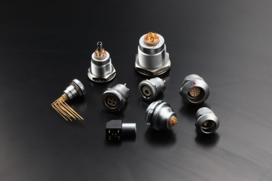
MOCO Connector
MOCO is committed to being one of the world's top manufacturers of industrial connectors and cablesEstablished in 2012, we have been growing stably year by year. With the excellent management andgreat efforts made during the past few years, we have developed a lot of popular products such asprecision circular push-pull connectors, M8 / M12 circular connectors, RF coaxial connectors, Mi-Specelectrical connectors,and high quality overmolding cable assemblies. And we are always ready forcustom products.
military connector manufacturers
1 note
·
View note
Text
Electric hand planers offer users the convenience of not having to handle a gas or electric planer. They are lightweight and easy to use. They come in various sizes and speeds, so you can find the perfect one for your needs. The four best electric hand planers of 2020 are the Porter-Cable PC60THP, the Dewalt DCP580B, the Wen 6530, and the DEWALT DW735X.Table of ContentsPORTER-CABLE Hand Planer, 6-Amp, 5/64-Inch (PC60THP)DEWALT 20V MAX Planer, 30,000 Cuts Per Minute, 2 mm Cut Depth, Brushless Motor, Bare Tool Only (DCP580B)WEN 6530 6-Amp Electric Hand Planer, 3-1/4-InchDEWALT Thickness Planer, Two Speed, 13-inch, 15 Amp, 20,000 RPM Motor (DW735X)Frequently Asked QuestionsIgnite Your PassionPORTER-CABLE Hand Planer, 6-Amp, 5/64-Inch (PC60THP)The PORTER-CABLE Hand Planer is a great choice for anyone looking for a reliable and affordable hand planer. With a 6-amp motor, it can remove material quickly and easily. The dust extractor bags attach to either side of the tool, keeping your work area clean. The overmold depth knob with 10 positive steps offers multiple depth control settings. The 3 chamfering grooves allow you to create multiple edge chamfers. The 11-1/2 in. cast aluminum shoe provides added control. The .078 in. depth of cut and .47 in. max rabbit depth make this hand planer a great choice for anyone looking for a fast and efficient way to remove excess material.DEWALT 20V MAX Planer, 30,000 Cuts Per Minute, 2 mm Cut Depth, Brushless Motor, Bare Tool Only (DCP580B)The first paragraph talks about the features of the product, and the second paragraph is about the advantages and disadvantages of the product. DEWALT 20V MAX Planer The DEWALT 20V MAX Planer is a cordless hand planer that features a brushless motor and 30,000 cuts per minute to achieve a fast removal rate. A maximum depth of cut of 5/64 inches (2 mm) and a calibrated depth adjustment knob allow for precise adjustments. The planer also features precision-machined front and back aluminum shoes for parallelism of cut, as well as a kickstand that allows the user to rest the planer on the work surface without gouging the material. The DEWALT 20V MAX Planer also has some advantages and disadvantages. The advantages include the brushless motor which provides power and runtime, as well as the precision-machined front and back aluminum shoes which ensure parallelism of cut. However, the disadvantages include the fact that it is a bare tool only, which means that it does not come with a battery or charger, and that it is a bit on the expensive side, costing $249.WEN 6530 6-Amp Electric Hand Planer, 3-1/4-Inch has a 6 Amp motor that provides up to 34,000 cuts per minute. You can adjust the cutting depth anywhere from 0 to 1/8 inches with the 16 positive stops. The rabbeting guide lets you make rabbets up to 1 inch in size. The whole thing weighs 6 pounds, making it very lightweight and easy to maneuver. It comes with a power planer, dust bag, kickstand, parallel fence bracket, and a 2-year warranty. The Good: -lightweight and easy to maneuver -rabbeting guide lets you make rabbets up to 1 inch in size -6 Amp motor provides up to 34,000 cuts per minute -adjustable cutting depth The Bad: -some users have said that the quality of the cuts is not as good as a corded electric hand planer Overall, the is a good choice for a lightweight and easy-to-use electric hand planer. It has a 6 Amp motor that provides up to 34,000 cuts per minute and an adjustable cutting depth. The rabbeting guide is a nice feature that lets you make rabbets up to 1 inch in size. However, some users have said that the quality of the cuts is not as good as a corded electric hand planer.DEWALT Thickness Planer, Two Speed, 13-inch, 15 Amp, 20,000 RPM Motor (DW735X)The DEWALT Thickness Planer is a reliable and durable tool that is perfect for any woodworking project. The three knife cutter head delivers 30% longer knife life and makes knife changes faster and easier. The two-speed gear box allows users to change feed speed to optimizing cuts per inch at 96 or 179 CPI.
The fan-assisted chip ejection vacuums chips off of the cutter head and exhausts them out of the machine. The 19-3/4-inch cast aluminum base is 2 times more rigid than a standard 10-inch base and folding tables. The automatic carriage lock reduces the movement that causes snipe without the need for manual engagement by the user. The material removal gauge and extra large thickness scale deliver accurate cuts with every pass. The extra large turret depth-stop allows users to return to most frequently used thicknesses with ease. The purchase includes one stationary 13" Planer, in/out feed tables with fasteners (attached to the base of the Planer base), extra blades, and a dust hose adapter. The stand is not included. Frequently Asked QuestionsIn this Q&A, we will be comparing the 4 best electric hand planers of 2020. Let's get started! Q: What are the benefits of using an electric hand planer? A: There are many benefits to using an electric hand planer. The most common benefit is that electric hand planers are much faster than manual hand planers. They also have much more power than manual hand planers, meaning they are able to cut through wood with greater precision. Electric hand planers are also much quieter than manual hand planers, so they are perfect for use in areas where noise is an issue. last but not least, electric hand planers are much easier and faster to use than manual hand planers. Ignite Your PassionThis year, there are a few electric hand planers that stand out from the rest. Here are four of the best: PORTER-CABLE PC60THP: The PORTER-CABLE PC60THP is a powerful electric hand Planer that offers 6 Amps of cutting power and 5/64-inch cutting depth. ThisPlaner has a brushless motor that delivers 30,000 cuts per minute and a 2 mm cut depth. This Planer is ideal for those who require a high level of accuracy and precision when planing boards or panels. At just over 20 pounds, this product is also lightweight and easy to move around. DEWALT DCP580B: The DEWALT DCP580B is a powerful electric hand Planer that offers 30,000 cuts per minute and 2 mm cut depth. This Planer has a brushless motor that delivers a cutting depth of 2 mm and a fatigue-free operation. The DCP580B is also compact and lightweight, making it ideal for use in tight spaces. WEN 6530 6-Amp Electric Hand Planer: The WEN 6530 6-Amp Electric Hand Planer is a powerful product that offers a 3-1/4-inch Planing width and 6 Amps of cutting power. This Planer has a soft grip handle that ensures a comfortable and reassuring grip during use. Additionally, the 6530 features a lock-off switch to prevent accidental start-ups, and a depth gauge that makes it easy to set the Planer to the desired cut depth. DEWALT Thickness Planer: The DEWALT Thickness Planer is a powerful product that offers two speeds and a 13-inch cutting width. This Planer has a 15 Amp motor that delivers a 20,000 RPM speed and a depth of 13 inches. The Thickness Planer is ideal for precision and accuracy when planing wood into desired thicknesses.
0 notes
Text
Why Machine Vision Cables Are Imperative For Machine System?
Cable quality is an often disregarded element in enhancing the effectiveness of machine vision systems. Using inexpensive or consumer-grade mini camera link cable that are not designed to withstand industrial uses and conditions might reduce signal output including the consequent image quality in situations where excellent output is required.

Because they lack the required cable shielding to prevent the signals from overlapping, subpar cables that are not made to sustain industrial use are especially susceptible to crosstalk. Read this guide to find the best machine vision cables.
Finding the Cable Quality
In order to guarantee dependability, correct data transfer, as well as longer cable lifespan, computer vision cables need to be designed to resist the rigours of industrial settings and applications. A few qualities to consider include, although aren't limited to:
superior outer jacket fabric
layered shielding
The proper reinforcing of connectors (over-molding)
A complete performance test (not a lot sampling)
As previously said, a cable that has undergone some sort of performance testing is a clear sign of quality. While near-end crossover (NeXT), far-end interference, and return loss should be tested at a minimum, there are other variables that can help you get a more full view of the cable's performance potential.
Performance Evaluation
An issue that can happen when a connection is coupled to crossed or compressed wire pairs inside of a single link is called near-end crosstalk (NeXT). The test measures noise that occurs at the connection nearest to the source of the signal in a test setting and is expressed in decibels (dB).
Similar to NeXT, far-end crosstalk (FeXT) quantifies in dB noise that occurs at the opposite end of the signal's origin in a testing setting.
When testing a cable, return loss is the amount of signal that is lost after travelling its whole length and back.
Attenuation is the noise component that reduces the intensity of the signal.
Connections that are angled and overmolded:
Wire breakage can be avoided by using angled cable connections with over-molding connectors.
Enhanced Durability: Low Smoky Zero Halogen (LSZH) cabling jacketing is strong enough to tolerate halogen's high temperatures in specific defence and military applications.
Conclusion
In conclusion, these are the things to consider while buying machine vision cables. You can surely find a great cable now!
0 notes
Text
Unlock the power of cable assembly overmolding with Violin Technologies!
Strengthen inner wires, boost environmental resistance, and ensure optimal performance.
Trust our expertise for all your overmolding needs.
Contact us today!
https://www.violintec.com/best-cable-wireharness-company/

0 notes
Text

ARDUINO MEGA 2560
Arduino mega 2560 Atmega2560-16au compatible with Arduino is a micro-controller board based on the ATmega2560 IC. It has a USB host interface for connecting to Android phones through the MAX3421e IC.
The MEGA ADK is equipped with versatile components, including 54 digital input/output pins (15 of which can also function as PWM outputs), 16 analog inputs, 4 UARTs (hardware serial ports), a 16 MHz crystal oscillator, a USB connection, a power jack, an ICSP header, and a reset button. This board is based on the Mega 2560 design and shares similar features with the Mega 2560 and Uno. Additionally, it has an ATmega8U2 programmed as a USB-to-serial converter. In its third revision, the Mega ADK includes a resistor that pulls the 8U2 HWB line to ground for easier access to DFU (Device Firmware Upgrade) mode.
New features on the board include:
As a result of the -1.0 pin-out, the SDA and SCL pins are near the AREF pin, and two additional pins are placed near the RESET pin, the IOREF, which allows the shields to adjust to the board’s voltage. AVR boards, which operate at 5V, and Arduino Due boards, which operate at 3.3V, will both be compatible with shields in the future. The second pin is unconnected, and is reserved for future purposes.
Circuits with a stronger RESET function.
An external power supply or USB connection can be used to power the arduino mega 2560 R3 Android Accessory Development Kit (ADK). Power is selected automatically. External (non-USB) power can come from either an AC-to-DC adapter (wall-wart) or battery. An adapter can be connected by plugging a 2.1mm center-positive plug into the board’s power socket.
-Leads from a battery can be inserted in the GND and Vin pin headers of the POWER connector. Since the Mega R3 Android Accessory Development Kit (ADK) is a USB host, the phone will attempt to draw power from it when charging. When the ADK is power over USB, 500mA is available for the phone and board.
Features and specifications:
Arduino Mega 2560:
Atmel is the programmer
Microcontroller ATmega2560.
There are 54 digital input/output terminals (14 of which have programmable PWM outputs).
There are 16 analog inputs.
There are four UARTs (hardware serial ports).
A crystal clock with a frequency of -16 MHz.
-Bootloader that allows sketches to be downloaded via USB without having to go through other writers.
The device can be powered via USB or via an external power supply (not supplied).
A heavy gold plate construction is used.
16 MHz clock speed.
The bootloader uses 8 KB of the 256 KB flash memory.
-Operating voltage: 6 ~ 12 volts.
Arduino mega 2560 cable:
Pluggable on the hot side.
-Compatible with PCs.
Strain relief and PVC overmolding ensure error-free data transmission for a lifetime.
An aluminum under-mold shield helps meet FCC requirements for KMI/RFI interference.
In addition, foil and braid shields comply with fully rated cable specifications, reducing EMI/FRI interference.
High-Performance Error-Free Transmission.
Case made of transparent acrylic:
ARDUINO MEGA 2560 R3 (unassembled) compatible.
It is possible to adjust the cover.
Transparent color.
Acrylic is the material used.
The power of
follows:
What follows is:
The Arduino board’s input voltage when it’s powered by an external source (rather than 5 volts from the USB connection or another regulated power source). If you are using the power jack to supply voltage, you can access it through this pin.
In this pin, a regulated 5V is output from the board’s regulator. The board can be powered by the DC power jack (7 – 12V), the USB connector (5V), or the VIN pin (7-12V). It is not recommended to supply voltage to your board via the 5V or 3.3V pins, as it bypasses the regulator and can damage it.
The onboard regulator generates a 3.3 volt supply with a maximum current draw of 50 milliamps.
The ground pin is GND.
This pin on the Arduino board serves as the voltage reference for the microcontroller. A properly configured shield can read the IOREF pin voltage and select the appropriate power source or enable voltage translators on the outputs for working with 5V or 3.3V.
The memory
In the arduino Mega 2560 R3 Android Accessory Development Kit (ADK), there is 256 KB of flash memory for storing code (of which 8 KB is used for the bootloader); 8 KB of SRAM, and 4 KB of EEPROM (which can be read and written).
The inputs and outputs
With pinMode(), digitalWrite(), and digitalRead() functions, the arduino Mega 2560 R3 Android Accessory Development Kit (ADK)’s 50 digital pins can be used as inputs and outputs. Each pin is powered by 5 volts and can provide or receive a maximum current of 40 milliamps. There is an internal pull-up resistor (20-50 kOhm) that is disconnected by default. Additionally, some pins have specialized functions:
It can receive (RX) and transmit (TX) TTL serial data. Pins 0 and 1 are also connected to the corresponding pins of the ATmega8U2 USB-to-TTL Serial chip.
The external interrupts are 2 (interrupt 0), 3 (interrupt 1), 18 (interrupt 5), 19 (interrupt 4), 20 (interrupt 3), and 21 (interrupt 21). The attachInterrupt() function can be used to trigger interrupts on low values, rising or falling edges, or changes in values.
The analogWrite() function provides 8-bit PWM output from 2 to 13 and 44 to 46.
There are four SPI pins on the ICSP header, which are physically compatible with the Uno, Duemilanove, and Diecimila: 50 (MISO), 51 (MOSI), 52 (SCK), 53 (SS).
MAX3421E is the USB host.
Maxim X3421E
It uses the SPI bus to communicate with Arduino. It uses the following pins:
Seven (RST), fifty (MISO), fifty-one (MOSI), and fifty-two (SCK).
Please do not use Digital pin 7 as an input or output because it is used for MAX3421E communication
PJ3 (GP_MAX), PJ6 (INT_MAX), PH7 (SS) are not broken out on headers.
A built-in LED is connected to digital pin 13. When the pin is HIGH, the LED is on, when it is LOW, it is off.
Wire library supports TWI communication using pins 20 (SDA) and 21 (SCL). These pins are not located in the same place as the TWI pins on the Duemilanove or Diecimila boards.
Inputs in the Mega R3 Android Accessory Development Kit (ADK) have a resolution of 10 bits each (i.e. 1024 different values). In default, they measure from ground to 5 volts, but you can adjust the upper end of their range by using the AREF pin and analogReference() function. There are a few other pins on the board as well:
A reference voltage for analog inputs. Use with analogReference.
Typically used to add a reset button to shields that block the board’s reset button. Bring this line LOW to reset the microcontroller.
The communication process
The Arduino Mega 2560 R3 Android Accessory Development Kit (ADK) offers various options for communicating with different devices. With the ATmega2560, there are four hardware UARTs available for TTL (5V) serial communication. Additionally, an ATmega8U2 on the board allows one of the UARTs to be used for USB communication and creates a virtual com port for software on the computer. While Windows machines may require a .inf file, OSX and Linux machines will automatically detect the board as a COM port. The Arduino software features a convenient serial monitor that enables straightforward exchange of textual data between the board and other devices.
The board’s RX and TX LEDs will blink to indicate data transmission through the ATmega8U2/16U2 chip and USB connection to the computer (note: not for serial communication on pins 0 and 1). Additionally, serial communication can be achieved on any of the MEGA ADK’s digital pins with the help of a Software-serial library. The ATmega2560 also supports TWI and SPI communication. To make use of the TWI bus, refer to the included Wire library in the Arduino software. For SPI communication, utilize the SPI library.
Any device that has a USB port can connect and interact with the Arduino MEGA 2560 ADK thanks to the USB host interface provided by the MAX3421E IC. You can use it to control Canon cameras, interact with keyboard, mouse, and game controllers such as the Wiimote and PS3 for example, as well as interact with many types of phones.
The programming language
The Mega R3 Android Accessory Development Kit (ADK) can be used with the Arduino software (download). For details, check out the reference and tutorials. The ATmega2560 on the MEGA ADK comes preburned with a boot-loader (the same on Mega 2560) that allows you to upload new code without using an external hardware programmer. In order to communicate with it, it uses the STK500v2 protocol (reference, C header files).
See these instructions for details on bypassing the bootloader and programming the microcontroller using Arduino ISP or similar. Source code for the ATmega8U2 firmware can be found in the Arduino repository. The ATmega8U2 is loaded with a DFU bootloader, which can be activated by:
Boards with Rev1:
Resetting the 8U2 requires connecting the solder jumper on the back of the board (near the map of Italy).
It is easier to put the 8U2/16U2 HWB line into DFU mode on Rev2 or later boards since a resistor pulls the line to ground. To load a new firmware, you can use Atmel’s FLIP software (Windows) or the DFU programmer (Mac OS X and Linux). For more information, see this user-contributed tutorial. If you use the ISP header and an external programmer, you can overwrite the DFU bootloader.
Reset (automatic) software
Instead of physically pressing the reset button, the Arduino MEGA ADK has the ability to be reset through a connected computer. This is achieved by connecting one of the hardware flow control lines (DTR) of the ATmega8U2 to the reset line of the ATmega2560 using a 100 nano-farad capacitor. By asserting this line (taking it low), the reset line briefly drops and resets the chip. The Arduino software utilizes this feature, allowing you to easily upload code by pressing a button in the environment.
This allows for a shorter timeout on the boot-loader, as the lowering of DTR can be easily synchronized with the beginning of the upload process. As a result, when the MEGA ADK is connected to a Mac OS X or Linux computer, it automatically resets and enters bootloader mode for a brief moment. During this time, if any data besides new code is sent to the board, it will be ignored as per its programming. However, it will intercept and process the first few bytes of data received after establishing a connection.
When a sketch on the board receives initial configuration or data upon startup, ensure that the corresponding software waits for a brief moment before transmitting this information. The MEGA ADK has a trace that can be deactivated to disable the auto-reset function. The two pads on either side of the trace can be soldered together to reactivate it. This is labeled as “RESET-EN”. Alternatively, you can potentially disable the auto-reset by connecting a 110-ohm resistor from 5V to the reset line; refer to this forum thread for further instructions.
0 notes
Text
Cable overmolding is a manufacturing process that combines and seals a wire with a connector resulting in a single unified part.
Aberdeen Technologies Inc. offers customers a one-stop shop for a variety of insert molding needs. We can solve your challenging and difficult injection molding problems with our leading edge technology and expertise, while keeping our focus on customer satisfaction. Our key personnel began working in the injection molding field in the early 1970’s and have accumulated a wealth of knowledge and experience which is able to be passed onto you, our customer.
https://www.aberdeentech.com/cable-molding
1 note
·
View note