
Don't wanna be here? Send us removal request.
Statistics
We looked inside some of the posts by dowelltech and here's what we found interesting.
Average Info
Notes Per Post
0
Likes Per Post
0
Reblog Per Post
0
Reply Per Post
0
Time Between Posts
2 days
Number of Posts By Type
Text
17
Last Seen Tumblr Blogs


Fun Fact
Hackers stole 65M passwords from Tumblr in 2013.
Text
How Can MST Fiber Distribution Terminal Assembly Transform Your FTTH Network Deployment

Fiber to the Home (FTTH) networks expand rapidly worldwide, with labor shortages and rising costs challenging operators. The MST Fiber Distribution Terminal Assembly, featuring a black plastic MST terminal enclosure for fiber cab and weatherproof MST fiber distribution box for FTTH n, streamlines deployment.

Factor Details Labor Costs Labor forms 60-80% of deployment costs. Installation Complex permitting and varied strategies increase timelines. The outdoor fiber optic MST terminal assembly with 8 p supports efficient, scalable rollouts in diverse environments.
Key Takeaways
The MST Fiber Distribution Terminal Assembly cuts labor needs by arriving pre-connectorized, allowing quick plug-and-play installation without complex splicing or special skills. Its modular design and factory-sealed enclosure lower costs by reducing installation time, maintenance, and the need for expensive equipment, helping operators scale networks efficiently. With flexible mounting options and strong environmental protection, the MST assembly ensures reliable, fast FTTH deployment in diverse settings, from cities to rural areas.
MST Fiber Distribution Terminal Assembly: Solving FTTH Deployment Challenges

Addressing Labor Shortages with MST Fiber Distribution Terminal Assembly Telecommunications industry surveys highlight several common FTTH deployment challenges: Cost constraints Technical expertise shortages Service disruption mitigation Quality assurance Community collaboration Labor shortages, especially the lack of skilled fiber splicing technicians, often slow FTTH rollouts. The MST Fiber Distribution Terminal Assembly, developed by Dowell, directly addresses this issue. The terminal arrives pre-connectorized and factory-sealed, eliminating the need for on-site splicing. Installers do not need to open the enclosure or perform complex fiber work in the field. This approach reduces the demand for specialized labor and minimizes training requirements. The MST Fiber Distribution Terminal Assembly features plug-and-play installation, allowing teams to connect drop cables quickly and securely. No terminal re-entry is required, which further reduces maintenance visits and labor hours. Multiple port and splitter options enable a single technician to serve many subscribers in one visit, streamlining the deployment process. Dowell’s user-friendly packaging and universal mounting bracket support rapid installation in diverse environments, from urban poles to rural handholes. These features collectively help operators overcome workforce shortages and accelerate network expansion. Reducing High Costs Using MST Fiber Distribution Terminal Assembly Cost remains one of the most significant barriers to FTTH deployment. Operators face high expenses related to labor, materials, and ongoing maintenance. The MST Fiber Distribution Terminal Assembly helps control these costs in several ways: Pre-terminated Design: The terminal arrives ready for installation, reducing the need for expensive field splicing equipment and skilled labor. Scalable Modular Options: Multiple port configurations (2, 4, 6, 8, or 12 ports) and internal splitters allow operators to match current needs and scale up as demand grows, avoiding unnecessary upfront investment. Reduced Maintenance: The factory-sealed, environmentally protected enclosure minimizes the risk of damage and service interruptions, lowering long-term maintenance costs. Efficient Deployment: Plug-and-play installation and flexible mounting options reduce installation time, which translates to lower labor costs and faster time-to-market. Feature MST Fiber Distribution Terminal Assembly Details Connector Technology Hardened connectors, factory-terminated, environmentally sealed Ingress Protection Rating IP68 (water and dust resistant) Operating Temperature Range -40°C to +85°C Cable Tensile Strength Up to 1200N long term Installation Options Wall-mounting, aerial, pole installation Dowell’s MST Fiber Distribution Terminal Assembly meets or exceeds industry standards for environmental protection and durability, ensuring a long service life and protecting the operator’s investment. Simplifying Installation Complexity with MST Fiber Distribution Terminal Assembly Traditional FTTH installations often involve complex splicing, multiple enclosure entries, and specialized tools. These factors increase the risk of errors and slow down deployment. The MST Fiber Distribution Terminal Assembly simplifies this process through its modular, pre-terminated design. Plug-and-play connections eliminate the need for field splicing. Hardened adapters and factory-sealed enclosures protect fiber connections from dust, moisture, and temperature extremes. Multiple mounting options (pole, pedestal, handhole, strand) provide flexibility for any deployment scenario. User-friendly packaging allows for easy cable management and unspooling during installation. Operators can deploy the MST Fiber Distribution Terminal Assembly in a wide range of environments, from dense urban areas to remote rural locations, with minimal disruption to existing services. Dowell’s solution supports rapid network upgrades and expansions, enabling operators to respond quickly to growing broadband demand. The modular design allows for incremental network growth without major infrastructure changes, making it easier to future-proof FTTH networks for emerging technologies.
MST Fiber Distribution Terminal Assembly: Accelerating and Enhancing FTTH Rollouts

Enabling Rapid Network Expansion with MST Fiber Distribution Terminal Assembly Network operators need solutions that support fast, scalable growth in both urban and rural areas. The MST Fiber Distribution Terminal Assembly enables rapid expansion through several key features: Pre-connected with hardened adapters, eliminating the need for fiber splicing and reducing installation complexity. Available in configurations from 2 to 12 ports, supporting customized network requirements and easy scalability. Robust IP67 waterproof rating and high mechanical strength ensure reliable operation in harsh environments. Flexible installation options, including wall, pole, aerial, and pedestal mounting, adapt to diverse deployment scenarios. Factory-sealed or field-assembled options provide project flexibility. Plug-and-play design and centralized connection points simplify deployment and maintenance, saving up to 40% in installation time. These advantages allow operators to expand FTTH networks efficiently, meeting the demands of both dense cities and remote communities. Improving Reliability and Service Quality through MST Fiber Distribution Terminal Assembly Service providers prioritize reliability and high-quality connections. The MST Fiber Distribution Terminal Assembly supports these goals by: Offering multiple output ports for distributing signals to many destinations, which enhances scalability and flexibility. Maintaining minimal signal loss through efficient signal management, preserving network performance. Supporting advanced features such as signal amplification and wavelength management, which help reduce downtime. Utilizing a rugged, weatherproof design that protects fiber connections from environmental hazards, ensuring consistent service even in extreme weather. These features help operators deliver dependable broadband with fewer interruptions and higher customer satisfaction. MST Fiber Distribution Terminal Assembly vs. Traditional Fiber Distribution Methods Aspect MST Fiber Distribution Terminal Assembly Traditional Fiber Distribution Methods Installation Efficiency Plug-and-play, pre-connectorized; reduces installation time by ~40% Requires field splicing; more complex and time-consuming Scalability Supports high-density connectors and splitters; customizable port counts Limited scalability; less flexible Environmental Durability IP67/IP68 rated; robust against weather and physical damage Often less robust; may lack high IP ratings Deployment Flexibility Multiple mounting options; supports FTTH, FTTA, 5G Fewer mounting options; less adaptable Signal Attenuation Reduced by factory pre-termination and fewer connection points Higher due to multiple splices Service Provisioning Enhanced by 15–30% due to simplified design Lower efficiency; manual splicing required The MST Fiber Distribution Terminal Assembly stands out for its efficiency, scalability, and durability, making it a superior choice for modern FTTH deployments. Operators gain a powerful tool for efficient FTTH deployment. In Anacortes, Washington, city staff maintained fiber rollout momentum during the pandemic by using MST terminals for no-contact installations. This approach supported community resilience and economic growth. MST solutions help networks adapt quickly to changing demands. By: Eric Tel: +86 574 27877377 Mb: +86 13857874858 E-mail: [email protected] Youtube: DOWELL Pinterest: DOWELL Facebook: DOWELL Linkedin: DOWELL Read the full article
0 notes
Text
How the FTTA 8 Port Waterproof Terminal Box Solves Outdoor Fiber Connectivity Challenges

The outdoor fiber cable market has surged, driven by the need for robust broadband and 5G infrastructure. Dowell’s FTTA 8 Port Waterproof Terminal Box stands out as an IP65 rated 8 port fiber optic cable termination bo. This outdoor 8 port fiber distribution box waterproof design ensures network reliability. Users trust this waterproof fiber optic terminal box with 8 ports for demanding environments.
Key Takeaways
The FTTA 8 Port Waterproof Terminal Box offers strong protection against water, dust, and harsh weather, ensuring fiber connections stay safe and reliable outdoors. Its simple, flexible design makes installation easier and faster, reducing costs and the need for specialized skills or tools. Easy access and organized cable management help technicians perform quick maintenance, minimizing network downtime and supporting long-term performance.
Outdoor Fiber Connectivity Challenges and the FTTA 8 Port Waterproof Terminal Box

Weather and Environmental Hazards Outdoor fiber optic installations face a range of environmental threats. Flooding, urban runoff, and natural disasters such as earthquakes, tornadoes, and wildfires can disrupt network infrastructure. Polluted floodwaters and toxic fumes from burning cable materials present additional hazards during recovery. UV radiation and temperature extremes also impact the longevity of fiber components. UV rays cause cable jackets to crack or become brittle, while temperature fluctuations can compromise seals and lead to material degradation. Outdoor fiber solutions must withstand these conditions to ensure reliable performance. Common environmental hazards include: Flooding and urban runoff carrying chemicals and debris Natural disasters with unpredictable impacts Polluted water and electrical hazards during recovery UV exposure and temperature extremes causing material fatigue Installation and Deployment Difficulties Deploying fiber optic terminal boxes outdoors introduces several challenges. Improper installation can result in broken cables, signal loss, and increased vulnerability to environmental damage. Excessive bending, defective connectors, and inadequate transmitting power often lead to network failures. High installation costs and a shortage of skilled professionals further complicate deployment, especially in remote areas. Durable, weatherproof enclosures like the FTTA 8 Port Waterproof Terminal Box help address these issues by simplifying installation and reducing the need for specialized tools. Maintenance and Accessibility Issues Maintenance of outdoor fiber terminal boxes often encounters obstacles such as moisture ingress, corrosion, and cable damage from poor management. Degraded seals allow water inside, leading to signal loss. Corrosion from salt and pollution damages metal parts, while overcrowding limits future upgrades. User-friendly access to internal components enables quicker repairs and reduces network downtime. Features like modular design and robust construction, as found in the FTTA 8 Port Waterproof Terminal Box, support efficient maintenance and long-term reliability. Network Reliability and Performance Network reliability depends on both environmental resilience and proper installation. Wired fiber connections offer higher stability and lower latency compared to wireless alternatives. However, outdoor conditions such as extreme weather, temperature swings, and physical impacts can degrade connectors and equipment, causing signal loss or interruptions. Protective measures, including weatherproof enclosures and regular maintenance, are essential. The FTTA 8 Port Waterproof Terminal Box provides a rugged solution that maintains signal integrity and supports stable network performance in challenging environments.
How the FTTA 8 Port Waterproof Terminal Box Overcomes Outdoor Fiber Issues

Superior Waterproof and Dustproof Protection Dowell’s FTTA 8 Port Waterproof Terminal Box delivers exceptional protection against water and dust, making it ideal for harsh outdoor environments. The enclosure meets the IP65 and IP68 standards, ensuring that fiber connections remain secure even during heavy rain or dust storms. The box’s construction from high-quality PC+ABS material provides resistance to aging and environmental wear, extending the lifespan of network infrastructure. The product’s compliance with ISO9001 demonstrates adherence to international quality management standards. These certifications confirm the terminal box’s suitability for demanding outdoor applications. The fully enclosed structure, sealed cable entries, and reinforced adapters work together to prevent moisture and dust ingress, safeguarding critical fiber connections. Note: The FTTA 8 Port Waterproof Terminal Box stands out by meeting both IP65 and IP68 ratings, offering higher protection than many competing products. Design Feature Description Material PC+ABS, anti-aging, wet-proof material for environmental resistance. Protection Rating IP65 and IP68 rated for high-level waterproof and dustproof protection. Cable Entry Diameter Sealed entries from 8-14mm to prevent ingress of dust and moisture. Flip-Up Distribution Panel Allows easy access for maintenance without compromising waterproof seal. Integrated Cable Management Organizes cables to prevent dust and moisture ingress and maintain performance. Simplified and Flexible Installation Features Dowell designed the FTTA 8 Port Waterproof Terminal Box for straightforward installation in various outdoor scenarios. The box includes wall mounting kits, screws, cable ties, and heat shrink protective sleeves, making deployment convenient and efficient. Technicians can mount the box on walls, poles, or strands, adapting to different site requirements. The simplified design allows non-expert technicians to install the terminal box with up to 40% higher efficiency compared to traditional enclosures. Features such as anti-torsion cable glands and internal strain relief protect cables during installation, reducing the risk of damage. The plug-and-play design eliminates the need for specialized splicing tools, lowering labor costs and minimizing installation errors. Installation accessories provided: Wall mounting kits Screws and cable ties Heat shrink protective sleeves Flexible mounting options: Wall-mounted Pole-mounted Strand-mounted Tip: The FTTA 8 Port Waterproof Terminal Box supports both armored and non-armored cables, accommodating a range of cable diameters for versatile deployment. Easy Maintenance and Serviceability The FTTA 8 Port Waterproof Terminal Box features a flip-up distribution panel, allowing technicians to access internal components quickly for repairs or upgrades. This design eliminates the need to detach the entire box from the network, reducing operational downtime. Clearly labeled ports simplify identification, making troubleshooting and maintenance more efficient. Dowell’s all-in-one design integrates fiber clamping, splicing, fixing, storage, and distribution. Dedicated channels keep cables, pigtails, and patch cords organized and independent, streamlining maintenance and minimizing the risk of accidental damage. The robust PC+ABS enclosure and IP65-rated structure ensure durability, supporting reliable long-term use in outdoor environments. Callout: Versatile mounting options and a scalable design allow seamless integration and future-proofing, enabling hassle-free upgrades and repairs. Enhanced Network Stability and Performance Network stability remains a top priority for outdoor fiber deployments. The FTTA 8 Port Waterproof Terminal Box achieves this through a combination of mechanical strength, ingress protection, and advanced cable management. The enclosure withstands pulling forces up to 1200N, thanks to armored cable and strength member fixation. Torsion-proof cable glands relieve mechanical stress, preventing fiber breakage during installation and operation. The box’s design minimizes the number of connecting nodes, reducing signal loss and enhancing overall network stability. High-strength materials and an arc interface design provide shock resistance, maintaining normal operation in harsh conditions. The terminal box supports both 4G and 5G networks, ensuring compatibility with high-speed data transmission requirements. Performance Metric Description Ingress Protection IP68 rating ensures waterproofing and dust resistance, protecting internal components. Mechanical Strength Withstands pulling force of 1200N, ensuring durability under stress. Signal Integrity Reduces signal loss by minimizing connecting nodes, supporting stable network performance. Installation Efficiency Increases efficiency by 40%, reducing human error and downtime. Additional features supporting performance: Bending radius of 20D reduces cable stress and prevents fiber damage. Pre-assembled waterproof cable assemblies minimize signal attenuation. Splice protection sleeves and PLC splitters can be securely mounted inside for flexible network configurations. Dowell’s FTTA 8 Port Waterproof Terminal Box provides a comprehensive solution for outdoor fiber connectivity, combining robust protection, easy installation, and reliable performance. The FTTA 8 Port Waterproof Terminal Box stands out as a practical choice for outdoor fiber connectivity. Operators benefit from a warranty of up to 10 years and 24/7 technical support. Key features include IP65-rated protection, versatile mounting, and low insertion loss. This solution ensures reliable performance in any environment. By: Eric Tel: +86 574 27877377 Mb: +86 13857874858 E-mail: [email protected] Youtube: DOWELL Pinterest: DOWELL Facebook: DOWELL Linkedin: DOWELL Read the full article
0 notes
Text
Fiber Optic Splice Closures: A Utility Company’s Secret to Rapid Repairs

Utility companies rely on Fiber Optic Splice Closures to deliver fast repairs and maintain stable service. These closures protect sensitive fiber connections from harsh environments. Their robust design supports swift, secure restoration of network function. Quick deployment reduces costly downtime, ensuring reliable communication for customers and critical infrastructure.
Key Takeaways
Fiber optic splice closures protect delicate fiber connections from harsh weather and damage, ensuring stable and reliable network service. Their smart design allows quick access and easy repairs, helping utility companies reduce costly downtime and restore service fast. Using modular, weatherproof closures and following best practices like proper sealing and testing leads to longer-lasting networks and lower maintenance costs.
Fiber Optic Splice Closures: Function, Features, and Importance
What Are Fiber Optic Splice Closures? Fiber optic splice closures serve as protective enclosures for fiber optic cable splices. Utility companies use these closures to shield sensitive fiber connections from environmental hazards such as moisture, dust, and extreme temperatures. Manufacturers construct these closures from high-strength plastics or stainless steel, ensuring durability and waterproof performance. Each closure contains a main body, splice trays for organizing fibers, sealing elements to keep out contaminants, cable glands for secure entry, and mounting brackets for installation. Sealing mechanisms like gels, gaskets, and pull-and-shrink tubing maintain the integrity of the internal splices. This robust construction allows for installation in aerial, underground, and indoor environments, making fiber optic splice closures a versatile solution for network protection. Core Functions: Protection and Organization Fiber optic splice closures play two critical roles in utility networks: protection and organization. They enclose fiber splices in a rugged, sealed housing, preventing damage from water, dust, and mechanical stress. Splice trays inside the closure keep fibers neatly organized, reducing the risk of tangling or breakage. Strain relief hardware secures cables, minimizing stress on the fibers during installation and maintenance. Service loops of excess fiber are stored inside or near the closure, allowing for easier future repairs or upgrades. Different closure types—such as dome, in-line, aerial, and pedestal—support various installation environments and cable entry needs. Proper cable preparation, grounding, and sealing ensure long-term network integrity. Tip: Neat fiber management inside closures, especially dome types, simplifies re-entry and reduces the risk of fiber damage during network modifications. Dowell, a leading provider in the industry, designs fiber optic splice closures that integrate advanced organization features. Their closures often include modular splice trays and patch panel adapters, enhancing both protection and cable management for utility networks. Key Features for Rapid Repairs: Accessibility, Weatherproofing, and Modularity Rapid repairs depend on the accessibility and design of fiber optic splice closures. Compression seal technology and O-ring sealing allow for easy assembly and watertight protection. Many closures require no specialized tools for installation or access, enabling technicians to work efficiently in the field. Mid-access designs let installers add closures over existing cables with minimal disturbance. Hinged splice trays, unibody storage baskets, and removable components improve access to spliced fibers, reducing repair time. Weatherproofing stands as a crucial feature. Closures use durable outer shells, elastic rubber rings, and dome-shaped designs to protect against rain, snow, UV radiation, and physical damage. These features ensure that fiber connections remain intact and functional, even in harsh conditions. Industry standards such as IEC 61753 and IP68 ratings confirm their ability to withstand water, dust, and temperature extremes. Modularity further accelerates repairs and upgrades. Modular closures support a wide range of fiber capacities and allow independent work on individual components. This design simplifies installation, maintenance, and network expansion. Dowell’s modular closures, for example, enable easy assembly, scalability, and compatibility with existing systems, making them a preferred choice for utility companies seeking efficient network management. Why Speed Matters: Impact of Downtime and Need for Fast Response Network downtime can have a severe financial impact on utility companies. According to the ITIC 2024 Hourly Cost of Downtime survey, large enterprises in the utilities sector face average downtime costs exceeding $5 million per hour. This high cost highlights the importance of rapid response and efficient repairs. Fiber optic splice closures help minimize downtime by enabling quick access and streamlined repairs. Accessibility features—such as re-enterable housings, numbered port layouts, and easy-to-use connectors—reduce the complexity and duration of fieldwork. These closures also support fast troubleshooting and maintenance, even in challenging environments like aerial or underground installations. Note: Fast, reliable repairs not only save money but also ensure continuous service for critical infrastructure and customers. By choosing advanced fiber optic splice closures from trusted suppliers like Dowell, utility companies can maintain high network reliability, reduce repair times, and protect their bottom line.
Fiber Optic Splice Closures in Utility Operations

Real-World Scenarios: Emergency Repairs and Outage Response Utility companies often face emergencies that threaten network stability. The Matanuska Telephone Association (MTA) in Alaska provides a notable example. After a 7.1 magnitude earthquake, MTA used fiber optic splice closures as part of its emergency restoration plan. These closures enabled rapid repairs for both aerial and underground cables. Proper sealing prevented water ingress and fiber stress, while OTDR testing verified restoration quality. This approach minimized network damage and restored service quickly. Compared to alternatives, breathable closures offer fast installation—typically within 45 minutes—and cost-effective protection for fusion splices. Their design reduces labor and speeds up outage response, making them ideal for urgent repairs. Choosing the Right Fiber Optic Splice Closure: Durability, Capacity, and Compatibility Selecting the right closure ensures long-term network reliability. Utility companies evaluate durability by choosing closures made from engineering plastics like ABS or PC, or high-strength aluminum alloy for outdoor use. These materials resist corrosion, aging, and impact. Sealing materials such as rubber and silicone provide waterproof and dustproof protection. Compliance with GR-771-CORE standards confirms environmental durability. Capacity and compatibility also matter. Closures must accommodate the required number of fibers and support various cable types and splicing methods. The table below compares two common closure types: Closure Type Fiber Capacity Ideal Applications Advantages Limitations Horizontal (In-Line) Up to 576 Aerial, underground High density, linear layout Needs more space Vertical (Dome) Up to 288 Pole-mounted, subsurface Compact, water-deflecting design Lower capacity than in-line Dowell offers closures that meet these criteria, ensuring compatibility and durability for diverse utility networks. Best Practices for Fast Deployment and Maintenance Efficient deployment starts with careful planning and site surveys. Technicians prepare cables, perform fusion splicing, and organize fibers in trays. Proper sealing with heat-shrink tubing or gel technology ensures environmental protection. OTDR testing verifies splice quality. Regular inspections and cleaning prevent contamination and maintain performance. Technician training, such as hands-on emergency restoration courses, reduces errors and speeds up repairs. Dowell supports these best practices by providing modular, user-friendly closures that simplify installation and maintenance. Fiber Optic Splice Closures help utility companies minimize downtime and maintain reliable service. These closures feature modular designs, advanced weatherproofing, and high splice capacity, which support rapid, effective repairs. Advanced Feature Benefit for Utilities Modular Design Faster repairs and easier upgrades Improved Sealing Fewer outages from environmental damage Utility companies that follow best practices report lower maintenance costs and longer closure lifespans.
FAQ
What is the typical lifespan of a fiber optic splice closure? Most closures last 20 years or more. Manufacturers design them to withstand harsh weather, UV exposure, and physical stress. Can technicians re-enter a closure for future repairs or upgrades? Yes. Many closures feature re-enterable designs. Technicians can open them for maintenance, upgrades, or troubleshooting without damaging the internal fibers. How do utility companies test the integrity of a splice closure after installation? Technicians use OTDR (Optical Time Domain Reflectometer) testing. This tool checks for signal loss, confirming proper splicing and sealing. By: Eric Tel: +86 574 27877377 Mb: +86 13857874858 E-mail: [email protected] Youtube: DOWELL Pinterest: DOWELL Facebook: DOWELL Linkedin: DOWELL Read the full article
0 notes
Text
Why Fiber Optic Splitters Are the Backbone of Modern FTTH Networks
A fiber optic splitter distributes optical signals from a single source to many users. This device supports point-to-multipoint connections in FTTH networks. The fiber optic splitter 1x2, fiber optic splitter 1x8, multimode fiber optic splitter, and plc fiber optic splitter all provide reliable, passive signal delivery.
Key Takeaways
Fiber optic splitters share one high-speed internet signal with many users, making networks efficient and reliable. Using splitters lowers costs by reducing cables, installation time, and power needs, simplifying network setup and maintenance. Splitters allow easy network growth by adding more users without major changes, supporting both small and large deployments.
Fiber Optic Splitter Fundamentals
What Is a Fiber Optic Splitter? A fiber optic splitter is a passive device that divides a single optical signal into multiple signals. Network engineers use this device to connect one input fiber to several output fibers. This process allows many homes or businesses to share the same high-speed internet connection. The fiber optic splitter does not require power to operate. It works well in both indoor and outdoor environments. How Fiber Optic Splitters Work The fiber optic splitter uses a special material to split light signals. When light enters the device, it travels through the splitter and exits through several output fibers. Each output receives a portion of the original signal. This process ensures that every user gets a reliable connection. The splitter maintains signal quality, even as it divides the light. Note: The efficiency of a fiber optic splitter depends on its design and the number of outputs. Types of Fiber Optic Splitters Network designers can choose from several types of fiber optic splitters. The two main types are Fused Biconical Taper (FBT) splitters and Planar Lightwave Circuit (PLC) splitters. FBT splitters use fused fibers to split the signal. PLC splitters use a chip to divide the light. The table below compares these two types: Type Technology Typical Use FBT Fused fibers Small split ratios PLC Chip-based Large split ratios Each type offers unique benefits for different FTTH network needs.
Fiber Optic Splitter Roles and Benefits in FTTH Networks
Efficient Signal Distribution A fiber optic splitter enables a single optical signal to reach many users. This device divides the light from one fiber into several outputs. Each output delivers a stable and high-quality signal. Service providers can connect multiple homes or businesses without installing separate fibers for each location. This approach ensures efficient use of network resources. Tip: Efficient signal distribution reduces the need for extra cables and equipment, making network management easier. Cost Savings and Simplified Infrastructure Network operators often choose a fiber optic splitter to lower costs. By sharing one fiber among many users, companies save on both material and labor expenses. Fewer cables mean less digging and less time spent on installation. Maintenance becomes simpler because the network has fewer points of failure. The passive nature of the splitter also eliminates the need for electrical power, which further reduces operational costs. Key cost-saving benefits include: Lower installation expenses Reduced maintenance needs No power requirements Scalability and Flexibility for Network Growth Fiber optic splitters support network growth with ease. Providers can add new users by connecting more output fibers to the splitter. This flexibility allows networks to expand as demand increases. The modular design of splitters fits both small and large deployments. Service providers can upgrade or reconfigure the network without major changes to the existing infrastructure. Technical Features for Modern Deployments Modern fiber optic splitters offer advanced features that meet today’s network demands. These devices maintain signal quality even when splitting the light into many outputs. They resist environmental changes such as temperature and humidity. Splitters come in different sizes and configurations, including rack-mounted and outdoor models. This variety allows engineers to select the best option for each project. Feature Benefit Passive operation No external power needed Compact design Easy installation High reliability Consistent performance Wide compatibility Works with many network types Real-World FTTH Application Scenarios Many cities and towns use fiber optic splitters in their FTTH networks. For example, a service provider may install a 1x8 splitter in a neighborhood. This device connects one central office fiber to eight homes. In apartment buildings, splitters distribute internet to each unit from a single main line. Rural areas also benefit, as splitters help reach distant homes without extra cables. Note: Fiber optic splitters play a key role in delivering fast and reliable internet to both urban and rural communities. A fiber optic splitter helps deliver fast, reliable internet to many homes. Network providers trust this device for its efficiency and cost savings. As more people need high-speed connections, this technology remains a key part of modern FTTH networks. Reliable networks depend on smart solutions like fiber optic splitters.
FAQ
What is the typical lifespan of a fiber optic splitter? Most fiber optic splitters last over 20 years. They use durable materials and require little maintenance in both indoor and outdoor environments. Can fiber optic splitters affect internet speed? A splitter divides the signal among users. Each user receives a portion of the bandwidth. Proper network design ensures everyone gets fast, reliable internet. Are fiber optic splitters difficult to install? Technicians find splitters easy to install. Most models use simple plug-and-play connections. No special tools or power sources are needed. By: Eric Tel: +86 574 27877377 Mb: +86 13857874858 E-mail: [email protected] Youtube: DOWELL Pinterest: DOWELL Facebook: DOWELL Linkedin: DOWELL Read the full article
0 notes
Text
Fire-Rated Fiber Optic Enclosures: Compliance for Commercial Buildings

Fire-Rated Fiber Optic Enclosures help commercial buildings meet strict fire safety codes. These enclosures, including Fiber Optic Splice Closure and Vertical Splice Closure, block fire from spreading through cable routes. A 3 Way Fiber Optic Enclosure or Vertical Heat-Shrink Joint Closure also protects network equipment and keeps fire barriers strong.
Key Takeaways
Fire-rated fiber optic enclosures protect buildings by blocking fire, smoke, and heat from spreading through cable routes, helping meet strict fire safety codes. Choosing the right enclosure means matching fire resistance ratings, certifications, and materials to the building’s environment and code requirements. Proper installation, labeling, and regular maintenance ensure long-term safety, compliance, and protection of critical network infrastructure.
Fire-Rated Fiber Optic Enclosures: Definition and Role
What Are Fire-Rated Fiber Optic Enclosures Fire-Rated Fiber Optic Enclosures serve as protective housings for fiber optic cables in commercial buildings. Manufacturers design these enclosures to withstand high temperatures and block the passage of flames, heat, and smoke. By sealing cable penetrations in fire-resistance rated walls, floors, and ceilings, these enclosures help maintain the integrity of fire-rated barriers. Specialized products, such as intumescent blocks and fire protection plugs, address irregular or hard-to-reach cable pathways. These solutions reinforce compromised drywall or concrete, keeping fire and smoke contained within designated compartments. This containment extends evacuation time and limits fire spread, which is critical for occupant safety. Importance for Commercial Building Compliance Commercial buildings must comply with strict fire safety codes. Fire-Rated Fiber Optic Enclosures play a vital role in meeting these requirements. Non-compliance can result in serious consequences: Denied insurance claims for fire-related losses Increased insurance premiums after inspections Coverage limitations or exclusions Potential policy cancellation for severe violations Fines and citations from regulatory agencies or fire marshals Correction orders that may restrict business operations Emergency repair costs that exceed planned budgets Reputational damage that can last beyond the repair period Non-compliant fire doors and barriers can increase average fire damage costs by about 37% in commercial settings, according to NFPA data. Regulatory authorities may impose fines, citations, or legal actions. Insurance providers often view compliance favorably, which can reduce premiums and liability risks. Fire-Rated Fiber Optic Enclosures help building owners avoid these risks and protect both people and property.
Fire-Rated Fiber Optic Enclosures: Fire Safety Standards and Certifications
NEC Article 770 and NFPA 70 Requirements The National Electrical Code (NEC) Article 770 and NFPA 70 set the foundation for fire safety in fiber optic installations. These codes require that Fire-Rated Fiber Optic Enclosures and cables do not increase the risk of fire or smoke spread within a building. Installers must firestop all penetrations through fire-rated walls, floors, and ceilings using approved methods. This preserves the fire resistance rating of each barrier. Cables must be installed securely, using hardware that avoids damage. In air-handling spaces, nonmetallic cable ties must have low smoke and heat release properties. A key aspect of compliance involves selecting the correct cable type for each building environment. The NEC classifies optical fiber cables by their fire resistance and smoke characteristics. The table below summarizes which cable types are permitted in specific spaces: Cable Type Plenum Riser General Use Ducts/Raceways Shafts OFNP/OFCP Y* Y* Y* Y* Y* OFNR/OFCR N Y* Y* Y* Y* OFNG/OFCG N N Y* N N OFN/OFC N N Y* N N Y indicates permitted use, subject to limitations in NEC sections 770.110 and 770.113. Circuit integrity (CI) cables used for critical systems must meet a minimum two-hour fire rating, tested according to ANSI/UL 2196. These requirements align with additional fire test standards, such as NFPA 262 and UL 1685. Dowell provides Fire-Rated Fiber Optic Enclosures that meet these rigorous standards, supporting safe and compliant installations in commercial buildings. UL, IEC, and ANSI Certifications Certifications from organizations such as UL (Underwriters Laboratories), IEC (International Electrotechnical Commission), and ANSI (American National Standards Institute) validate the fire performance of fiber optic enclosures. UL certification, for example, confirms that enclosures and cables have passed standardized fire resistance and smoke emission tests. IEC standards, including IEC 60332 and IEC 61034, address flame propagation and smoke density for optical fiber cables. ANSI standards, such as ANSI/UL 2196, set benchmarks for circuit integrity during fire exposure. Manufacturers like Dowell design and test their Fire-Rated Fiber Optic Enclosures to meet or exceed these certifications. Building owners and contractors should always verify that products carry the appropriate listings and markings. This ensures that the selected enclosures will perform as required during a fire event and satisfy inspection requirements. Practical Meaning of Compliance Compliance with fire safety standards and certifications delivers real-world benefits for commercial buildings. Properly installed and certified Fire-Rated Fiber Optic Enclosures help maintain the integrity of fire barriers, limit the spread of flames and smoke, and protect critical network infrastructure. Insurers often require documented compliance before issuing or renewing policies. Regulatory agencies may conduct inspections to verify that all cable penetrations and enclosures meet code requirements. Recent changes in the NEC reflect ongoing efforts to streamline and clarify fire safety rules. The 2026 NEC update moves the content of Article 770 into new articles within the limited-energy systems section. This organizational change does not alter the core requirements for fire-rated enclosures but highlights the importance of staying current with evolving codes. Dowell remains committed to providing up-to-date solutions that help clients achieve and maintain compliance. Tip: Regularly review code updates and product certifications to ensure ongoing compliance and avoid costly retrofits or penalties.
Fire-Rated Fiber Optic Enclosures: Materials and Construction

Fire-Resistant Materials (Plenum, PVC/Riser, LSZH) Manufacturers select materials for fiber optic enclosures based on fire resistance and safety requirements. Plenum, PVC/riser, and LSZH (Low Smoke Zero Halogen) materials each offer distinct fire ratings. Plenum-rated cables, marked as OFNP, provide the highest flame retardancy and are essential in air handling spaces. These cables use materials like fluorinated ethylene polymer (FEP) or specialized PVC, which limit flame spread and produce minimal smoke. LSZH cables contain no halogens, so they emit very little smoke and no toxic gases during combustion. This feature makes LSZH ideal for confined or public spaces where smoke inhalation poses a significant risk. PVC/riser cables, labeled OFNR, are suitable for vertical runs between floors but have lower fire resistance and higher toxicity due to halogen content. Feature PVC/Riser Cable Plenum Cable LSZH Cable Flame Resistance Average Very Good Good Self-Extinguish Poor Very Good Good Halogen Content Contains Halogens Contains Halogens* Halogen-Free Smoke Production Higher Very Low Very Low Toxicity Higher Lower Lowest *Note: Some plenum cables are halogen-free but generally contain halogens. Construction Methods for Fire Rating Engineers design enclosures to meet strict fire resistance standards. Tests such as UL 94 and PH120 evaluate how materials behave under fire conditions. A V-0 rating under UL 94 means the material self-extinguishes quickly and does not drip flaming particles. PH120 certification ensures the enclosure protects internal hardware for up to 120 minutes during a fire. Manufacturers use vertical and horizontal burn tests, mechanical shock, and water spray simulations to verify performance. These methods ensure that enclosures maintain their integrity and protect network components during fire exposure. Comparison of Enclosure Options Selecting the right enclosure involves balancing durability, fire resistance, installation ease, and cost. Plenum cables offer the highest fire rating and durability, making them suitable for air handling spaces but at a higher price. Riser cables provide moderate fire resistance and are easier to install in vertical shafts. LSZH cables excel in low smoke and toxicity, ideal for sensitive environments, though they are not direct substitutes for plenum cables. Outdoor cables, such as PE, resist weather but lack indoor fire ratings. Cable Type Durability Fire Resistance Ease of Installation Cost Considerations Plenum High Highest Requires compliance More expensive Riser Durable Moderate Easier in risers Less expensive LSZH Durable Good Specialized areas More expensive PE (Outdoor) High Not suitable Outdoor only Varies

Tip: Always match enclosure materials and ratings to the building’s fire safety requirements and installation environment for optimal protection and compliance.
Fire-Rated Fiber Optic Enclosures: Selection Criteria
Building Code and Regulatory Considerations Every commercial building must follow local, state, and national fire safety codes. Authorities such as the National Fire Protection Association (NFPA) and the International Building Code (IBC) set strict rules for cable management and fire barrier integrity. Inspectors often check if Fire-Rated Fiber Optic Enclosures meet these standards. Building owners should review the following before selecting an enclosure: Fire Resistance Rating: The enclosure must match or exceed the fire rating of the wall, floor, or ceiling it penetrates. Certification Requirements: Products should carry recognized certifications, such as UL or IEC, to ensure compliance. Documentation: Proper records of installation and product specifications help during inspections and insurance reviews. Note: Local codes may have unique requirements. Always consult with a licensed fire protection engineer or code official before finalizing product selection. Environmental and Application Factors The environment where the enclosure will be installed plays a major role in product selection. Different spaces in a commercial building present unique challenges. For example, air handling spaces require plenum-rated materials, while riser shafts need riser-rated products. Moisture, temperature, and exposure to chemicals can also affect performance. Key environmental and application factors include: Location: Indoor, outdoor, plenum, riser, or general use areas Temperature Range: Some enclosures must withstand extreme heat or cold Moisture and Corrosion Resistance: Wet or humid environments require enclosures with special seals or coatings Mechanical Protection: High-traffic or industrial areas may need reinforced enclosures A table can help compare environmental needs: Application Area Required Rating Environmental Challenge Recommended Feature Plenum Spaces Plenum (OFNP) Airflow, smoke control Low smoke, flame retardant Riser Shafts Riser (OFNR) Vertical fire spread Self-extinguishing Outdoor Areas UV/Weather Resistant Sun, rain, temperature Sealed, UV-stable Industrial Zones Impact Resistant Vibration, dust, chemicals Reinforced, gasketed Matching Features to Project Needs Selecting the right Fire-Rated Fiber Optic Enclosures involves more than just code compliance. Project managers must balance safety, performance, and budget. The following checklist can guide the decision-making process: Assess the Building Layout: Identify all fire-rated barriers and cable pathways. Determine Required Ratings: Match enclosure ratings to the fire resistance of each barrier. Evaluate Cable Types: Choose enclosures compatible with plenum, riser, or LSZH cables as needed. Consider Future Expansion: Select enclosures with extra capacity for future cable additions. Review Installation Requirements: Some enclosures offer tool-less entry or modular designs for faster installation. Check Maintenance Needs: Easy-access panels and clear labeling simplify inspections and repairs. Tip: Involve IT, facilities, and safety teams early in the planning process. Their input ensures the selected enclosures meet both technical and regulatory needs. A well-chosen enclosure protects network infrastructure, supports code compliance, and reduces long-term costs. Fire-Rated Fiber Optic Enclosures provide peace of mind for building owners and occupants by combining safety with reliable performance.
Fire-Rated Fiber Optic Enclosures: Installation and Maintenance
Installation Best Practices Proper installation ensures both safety and code compliance. Installers should follow these best practices: Select cables and raceways that meet NEC Article 770 requirements. Firestop every penetration of fire-rated walls, partitions, floors, or ceilings. Always follow manufacturer instructions and NEC 300.21. Restore the integrity of any fire barrier after making penetrations for fiber optic installations. Use plenum-rated cables and raceways in environmental air spaces, such as above suspended ceilings or below raised floors. Support cables with the building’s structural components and approved fittings. Avoid using ceiling grids or ceiling-support wires. Arrange cables neatly and in a workmanlike manner to comply with NEC 770.24. This also ensures easy access for future maintenance. Position above-ceiling cables so that suspended ceiling panels can be moved without obstruction, preventing code violations. Tip: Careful planning before installation reduces the risk of costly corrections and ensures long-term reliability. Labeling and Documentation Requirements Accurate labeling and thorough documentation help maintain compliance and simplify future inspections. Each enclosure and cable should display clear, durable labels that indicate fire rating, installation date, and cable type. Installers should maintain detailed records, including product certifications, installation diagrams, and fire barrier restoration details. Organized documentation supports smooth inspections and insurance claims. Inspection and Ongoing Maintenance Routine inspections keep systems safe and compliant. Facility teams should check enclosures for physical damage, label legibility, and barrier integrity. Maintenance schedules should include periodic testing of firestopping materials and prompt repair of any deficiencies. Regular reviews ensure that all components continue to meet evolving code requirements. Fire-Rated Fiber Optic Enclosures support compliance and protect vital infrastructure in commercial buildings. These enclosures prevent fire and toxic gas spread, offer durable protection against environmental hazards, and help reduce insurance costs. Their use enhances operational continuity and risk management for building owners. Protects critical components for up to four hours Reduces maintenance needs Supports installation in diverse environments By: Eric Tel: +86 574 27877377 Mb: +86 13857874858 E-mail: [email protected] Youtube: DOWELL Pinterest: DOWELL Facebook: DOWELL Linkedin: DOWELL Read the full article
0 notes
Text
Exploring What Sets OptiTap Waterproof Fiber Optic Adapter Apart for Outdoor Applications

The OptiTap waterproof fiber optic adapter from Corning sets a new standard for outdoor connectivity. This Waterproof Optic Adapter features robust engineering. The Corning Optitap SC waterproof fiber optic adapter delivers reliable performance in harsh environments. Hardened Corning Optitap adapter for outdoor fiber installations ensures network stability. Waterproof single-mode Corning Optitap connector a supports diverse network needs.
Key Takeaways
The OptiTap adapter offers superior protection with an IP68 rating, making it fully dustproof and waterproof for reliable outdoor use in harsh conditions. Its durable, corrosion-resistant, and UV-stable design ensures long-lasting performance even under extreme weather and sunlight exposure. The adapter supports quick, tool-free installation and broad compatibility with various fiber types and connectors, saving time and reducing costs.
OptiTap Waterproof Fiber Optic Adapter: Unmatched Protection and Durability

IP68 Waterproof and Dustproof Performance The OptiTap waterproof fiber optic adapter stands out with its IP68 rating, which exceeds the industry standard for outdoor fiber optic adapters. Many competing products, such as the Fiber Optic Mini SC Waterproof Adapter, only achieve an IP67 rating. The IP68 rating ensures complete protection against dust ingress and allows the adapter to withstand continuous immersion in water. This level of environmental sealing makes the OptiTap waterproof fiber optic adapter ideal for challenging outdoor conditions, where dust and moisture often threaten network reliability. Note: The IP68 rating of the OptiTap adapter provides a higher level of dustproof and waterproof protection compared to most outdoor adapters, ensuring stable performance even in the harshest environments. Feature Corning OptiTap SC Hardened Adapter IP Rating IP68 (higher dust and water protection) Durability Designed for harsh outdoor environments Environmental Sealing Meets highest environmental standards with sealed housing Dustproof Performance Superior to many other outdoor adapters rated IP67 Application Suitable for challenging outdoor conditions Dowell recognizes that environmental hazards can cause common failure modes in outdoor fiber optic adapters, such as water ingress and dust contamination. The robust sealing system of the OptiTap waterproof fiber optic adapter addresses these risks, ensuring long-term reliability for outdoor network deployments. Corrosion-Resistant and UV-Stable Construction Corning engineers the OptiTap waterproof fiber optic adapter with advanced materials that resist corrosion and UV degradation. The adapter features a hardened outdoor-grade plastic shell, which withstands acid, alkali, and chemical exposure. This construction ensures that the adapter maintains its mechanical integrity and optical performance over time, even when exposed to harsh outdoor elements. Material Type Description Hardened outdoor-grade plastic Provides corrosion resistance and durability in harsh outdoor environments IP68-rated sealing Ensures protection against water, dust, and environmental hazards including corrosion Rugged construction Designed to withstand extreme weather conditions, enhancing corrosion resistance The OptiTap waterproof fiber optic adapter also incorporates special plastic materials certified for UV resistance according to ISO 4892-3. This UV stability prevents material degradation from prolonged sunlight exposure, which is essential for outdoor installations such as FTTH and 5G networks. The adapter’s UV-resistant design ensures that it continues to deliver reliable connectivity, even after years of service in direct sunlight. Tip: UV stability and corrosion resistance are critical for outdoor fiber optic adapters. The OptiTap waterproof fiber optic adapter’s advanced materials help network operators like Dowell achieve long-lasting, maintenance-free performance. Engineered for Extreme Temperatures and Weather Outdoor fiber optic networks often face extreme temperature fluctuations and severe weather. The OptiTap waterproof fiber optic adapter operates reliably within a wide temperature range, from -40°C to +85°C. This capability ensures stable performance in both freezing winters and scorching summers. Source Operating Temperature Range Carefiber -40°C to +85°C Fiberroom -40°C to +85°C The adapter’s rugged design resists not only temperature extremes but also mechanical stress, humidity, and physical impacts. Corning’s engineering ensures that the adapter maintains low insertion loss and high return loss, preserving signal integrity in all weather conditions. Dowell leverages these features to support robust outdoor network deployments, minimizing the risk of signal degradation due to environmental factors. The adapter’s precise fiber end-face alignment maximizes optical energy coupling, reducing signal loss. The ceramic connection interface and auxiliary sealing components further enhance stability and environmental resistance. Network operators trust the OptiTap waterproof fiber optic adapter for its proven ability to withstand the toughest outdoor environments, ensuring uninterrupted connectivity for critical applications.
OptiTap Waterproof Fiber Optic Adapter: Installation, Compatibility, and Real-World Applications

Tool-Free, Plug-and-Play Installation Network operators demand fast, reliable installations, especially in outdoor environments where time and weather are critical factors. The OptiTap waterproof fiber optic adapter delivers a true plug-and-play experience. Technicians can complete installation in under two minutes, a significant improvement over traditional fiber splicing methods that often require 20 to 40 minutes per drop. This efficiency results from the factory-terminated design and tool-free connection process. Feature OptiTap Installation Time Traditional Fiber Splicing Installation Time Installation Time Under 2 minutes 20 to 40 minutes per drop Dowell leverages this rapid deployment capability to accelerate project timelines and reduce labor costs. The adapter’s compact form factor and intuitive design allow for easy integration into wall outlets, panels, and outdoor enclosures. Field technicians appreciate the reduction in specialized training and equipment, which further streamlines network expansion and maintenance. Tip: Quick, tool-free installation not only saves time but also minimizes the risk of installation errors, ensuring consistent network performance. Broad Compatibility with Fiber Types and Connectors The OptiTap waterproof fiber optic adapter supports a wide range of fiber types and connector standards, making it a versatile solution for diverse network architectures. It accommodates Mini SC/APC connectors and integrates seamlessly with Corning equipment. The adapter operates across a wavelength range of 1260–1650nm, which aligns with single-mode fiber applications commonly found in FTTH, FTTB, and FTTx networks. Dowell selects the OptiTap waterproof fiber optic adapter for its ability to support both hybrid and non-hybrid cables. The adapter fits round cables with outer diameters from 5.0mm to 14mm and flat cables with dimensions up to 4.6x8.9mm. This broad compatibility surpasses many traditional outdoor adapters, which often have more limited cable support. Feature/Specification OptiTap Waterproof Fiber Optic Adapter Traditional Outdoor Adapters Cable Types Supported Hybrid and non-hybrid Less flexible Round Cable OD 5.0mm to 14mm Narrower range Flat Cable Dimensions 4.0x7.0mm to 4.6x8.9mm Often not supported Connector Types SC/APC, MPO, LC Limited options Waterproof Rating IP68 Comparable or lower Operational Efficiency Saves 40% operating time Less efficient This flexibility allows Dowell to deploy the adapter in a variety of outdoor scenarios, from aerial and pole-mounted installations to underground and direct burial applications. The adapter’s compliance with IEC 61753-1 standards ensures high reliability and performance, even in the most demanding environments. Proven Performance in FTTH, 5G, and Harsh Outdoor Deployments The OptiTap waterproof fiber optic adapter has demonstrated outstanding performance in real-world deployments. In large-scale urban FTTH projects, Dowell has used the adapter to reduce installation times and project costs, leading to higher customer satisfaction. The adapter’s IP68 waterproof rating and rugged construction ensure durability and environmental adaptability, which are critical for outdoor fiber networks. FTTH (Fiber to the Home): Enables rapid, tool-free subscriber connections without the need for fusion splicing. This feature is ideal for last-mile deployments, where speed and reliability are essential. 5G and Small Cell Backhaul: Provides robust, weatherproof fiber links for antenna-to-network interfaces in 5G and small cell networks. Rural Fiber Networks: Offers scalable, cost-effective solutions for underserved areas, supporting both hybrid and non-hybrid cable types. Outdoor Distribution Boxes: Simplifies plug-and-play terminations in outdoor terminals, handholes, and distribution cabinets. Emergency Communications: Supports rapid deployment for disaster recovery and field operations in challenging environments. Telecom Towers and Municipal Broadband: Used in FTTA (Fiber to the Antenna) and municipal broadband networks, where weatherproof, hardened connections are required. Note: The OptiTap waterproof fiber optic adapter maintains low insertion loss (≤0.20 dB) and high return loss (≥60 dB), ensuring excellent signal integrity in both indoor and outdoor environments. Dowell’s field experience confirms the adapter’s ability to withstand mechanical stress, temperature extremes, and high humidity. The design supports up to 1000 mating cycles and endures repeated drops and cable tension, making it a reliable choice for mission-critical outdoor networks. Network operators choose this adapter for its proven durability, reliable signal transmission, and easy installation. Key Differentiator Description Durable and Resilient Design Hardened construction withstands harsh conditions, ensuring reliable outdoor performance. Optimized Signal Transmission Low insertion loss and high return loss support efficient data transfer. Compatibility with Fiber Types Supports single-mode and multimode fibers for versatile applications. Easy Installation and Maintenance User-friendly design reduces downtime and operational costs. The adapter’s certifications, robust warranty, and 24/7 support further ensure long-lasting, dependable outdoor connectivity. By: Eric Tel: +86 574 27877377 Mb: +86 13857874858 E-mail: [email protected] Youtube: DOWELL Pinterest: DOWELL Facebook: DOWELL Linkedin: DOWELL Read the full article
0 notes
Text
How the 16 Port Waterproof Terminal Box Improves Fiber Network Reliability in 2025
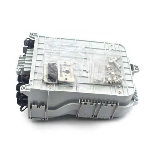
The 16 Port Waterproof Terminal Box delivers robust protection for fiber connections in demanding environments. Network operators rely on the high capacity 16 fiber FTTH distribution box for f to shield infrastructure from moisture and dust. The Easy install 16 port FTTH fiber terminal box with advanced sealing technology ensures stable performance. Many prefer the 16 port outdoor FTTH fiber optic access terminal b for critical deployments.
Key Takeaways
The 16 Port Waterproof Terminal Box protects fiber networks from water, dust, and physical damage with its IP65-rated, durable PC+ABS enclosure, ensuring reliable outdoor performance. Advanced cable management and easy maintenance features speed up installation and reduce downtime, making network upkeep simpler and more cost-effective. Its robust design and flexible installation options help network operators maintain stable, future-ready fiber connections in harsh environments.
Outdoor Fiber Challenges and the Role of the 16 Port Waterproof Terminal Box
Outdoor fiber networks in 2025 face a range of environmental and operational threats. Dowell’s 16 Port Waterproof Terminal Box provides a robust solution, engineered to overcome these challenges and ensure reliable fiber connectivity in the most demanding conditions. Moisture and Water Ingress Protection Moisture ingress remains one of the most significant threats to outdoor fiber networks. When seals degrade, water can penetrate the enclosure, causing signal loss, corrosion, and even complete network outages. According to industry standards, fiber optic terminal boxes must use high-impact plastics like ABS or polycarbonate and achieve a high IP rating to resist water and dust. The IP65 rating, defined by IEC 60529, ensures the enclosure is dust-tight and protected against low-pressure water jets, making it suitable for outdoor use. IP Rating Protection Level Typical Application IP54 Limited dust, splashing water Indoor use IP65 Dust-tight, low-pressure water jets Outdoor use IP66 Heavy water jets Harsh outdoor IP67 Temporary immersion Flood-prone areas IP68 Continuous submersion Underground/underwater Dowell’s 16 Port Waterproof Terminal Box meets and exceeds these requirements, providing a secure barrier against water ingress. Its robust sealing and high-quality PC+ABS construction ensure long-term protection, even in extreme weather conditions. This level of defense is critical for FTTH and 5G deployments, where network reliability is non-negotiable.

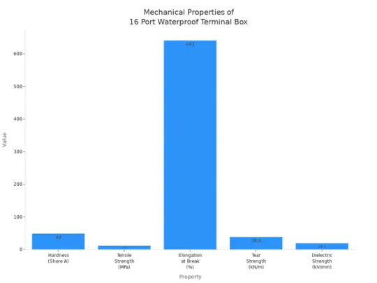
Defense Against Dust and Particle Contamination Dust and particle contamination can degrade fiber performance by settling on connector endfaces, causing signal attenuation and increased maintenance. Outdoor installations face multiple contamination sources: Airborne dust and debris from the environment Static electricity attracting particles Oils and lint from human contact Residues from dust caps and packaging Migration of contaminants during connector mating The 16 Port Waterproof Terminal Box achieves an IP65 dustproof rating, aligning with industry benchmarks for outdoor fiber distribution. This rating ensures complete protection against dust ingress, maintaining clean internal conditions and reducing the risk of signal loss. Dowell’s design also incorporates sealing gaskets and UV-stabilized materials, further minimizing contamination risks during installation and operation. Resistance to Physical Damage and Environmental Stress Outdoor fiber terminal boxes must withstand a variety of physical and environmental stresses. Common threats include: Humidity and salt corrosion, especially in coastal regions UV radiation and temperature fluctuations, which can weaken materials Ice formation inside cables during cold weather Wildlife interference and accidental damage from construction Acts of God, such as severe storms or accidental cuts from external activities Type of Damage / Environmental Stress Impact Dowell’s Design Features Humidity and Salt Corrosion Corrosion of metal parts Corrosion-resistant metals, PC+ABS housing UV Radiation and Temperature Fluctuations Material degradation UV-resistant plastics Cold Weather and Ice Formation Fiber bending, water freezing Waterproof seals, moisture barriers Wildlife and Construction Damage Mechanical damage Reinforced enclosure, robust mounting Moisture and Dust Signal degradation Seals, gaskets, IP65 rating Dowell’s 16 Port Waterproof Terminal Box demonstrates high resilience in standardized impact and stress tests. With a tensile strength of 11.8 MPa and elongation at break of 641%, the enclosure resists puncture, wear, and fatigue. The product’s certifications (ISO9001:2015, ISO14001, OHSAS18001) further validate its durability and manufacturing quality.
Power Integration and Advanced Cable Management Modern outdoor fiber deployments often require integrated power management to support active equipment. Key benefits include: Support for AC & DC power, breakers, battery storage, and surge protection Reliable operation of remote outdoor cabinets Enhanced resilience against power interruptions Simplified maintenance with organized power and fiber components in one enclosure Dowell’s 16 Port Waterproof Terminal Box also features advanced cable management. The flip-up distribution panel and multi-layer splicing trays separate feeder and drop cables, reducing the risk of kinks and bends. Quick-release designs and tool-free access speed up installation and maintenance. Proper cable alignment improves airflow and system reliability, while unique interlocking grooves prevent tangling and damage. These features can reduce cable management time by up to 60%, lowering maintenance costs and ensuring future-ready scalability. Tip: Efficient cable management not only speeds up installation but also minimizes long-term maintenance, making the network more reliable and cost-effective.
Key Features of the 16 Port Waterproof Terminal Box in 2025

IP65 Waterproof and Dustproof Enclosure The 16 Port Waterproof Terminal Box from Dowell features an IP65-rated enclosure that delivers robust protection for fiber optic connections. The enclosure is dust-tight and shields internal components from water jets, making it ideal for outdoor and industrial environments. The fully enclosed structure prevents dust and water ingress, supporting reliable operation in both indoor and outdoor settings. The box operates within a wide temperature range from -40°C to +85°C and tolerates humidity up to 85%. This level of protection ensures stable performance in FTTH networks, commercial buildings, and outdoor fiber deployments. Durable PC+ABS Construction for Longevity Dowell engineers the 16 Port Waterproof Terminal Box with high-quality PC+ABS material. This construction provides: Resistance to moisture, dust, and aging Impact resistance and antirust properties Stable performance and a long lifespan, even in harsh outdoor environments The PC+ABS material meets RoHS and REACH standards, reducing environmental impact while ensuring mechanical protection. Integrated Cable Management and Flexible Installation Efficient cable management is essential for network reliability. The terminal box supports: Multiple installation methods, including wall, pole, and aerial mounting Organized cable routing with 2 inlet ports and 16 outlet ports Multi-layer trays for selective access during installation and maintenance Storage for up to 2 meters of loose tube per port These features simplify installation, reduce labor costs, and support future network expansion. Proper cable management in the 16 Port Waterproof Terminal Box accelerates troubleshooting by up to 30%, minimizes downtime, and extends equipment life. Enhanced Sealing and Easy Maintenance Access Dowell incorporates advanced sealing technology in the terminal box. The design uses waterproof adapters and mechanical seals to prevent dust and water ingress. Fast insertion methods allow cable fixing and sealing outside the box, enabling quick installation without opening the enclosure. Easy access supports routine inspections, cleaning, and repairs without disrupting network service. Maintenance teams can check connectors, replace seals, and organize fibers efficiently, which helps maintain high network uptime and service reliability. Real-World Application: Outdoor Fiber Deployment Success Network operators deploy the 16 Port Waterproof Terminal Box in diverse environments, from urban FTTH rollouts to rural 5G infrastructure. Its robust construction and flexible installation options ensure reliable performance in challenging conditions. Dowell’s commitment to quality and innovation makes this terminal box a trusted solution for future-ready fiber networks. The 16 Port Waterproof Terminal Box stands out for its robust PC+ABS construction, IP65 protection, and versatile installation options. Network operators benefit from reduced maintenance, stable performance, and future-ready scalability. Industry certifications and advanced cable management ensure reliable operation in harsh outdoor environments. By: Eric Tel: +86 574 27877377 Mb: +86 13857874858 E-mail: [email protected] Youtube: DOWELL Pinterest: DOWELL Facebook: DOWELL Linkedin: DOWELL Read the full article
0 notes
Text
FTTA 10 Cores Pre-Connected Fiber Optic CTO Box Solves FTTx Installation Challenges in 2025

Network operators in 2025 face high installation costs and complex permitting for FTTx projects. The FTTA 10 Cores Pre-Connected Fiber Optic CTO Box streamlines deployment, reduces signal errors, and lowers labor expenses. Its Outdoor IP65 FTTA 10 Core Pre-Connected Fiber Opti design, Wall-Mountable FTTH 10 Core Fiber Optic Distributi capability, and Waterproof 1x8 PLC Splitter Ready 10 Core FTTA CTO features ensure reliable, scalable installations.
Key Takeaways
The FTTA 10 Cores Pre-Connected Fiber Optic CTO Box speeds up fiber network installation by eliminating manual splicing and reducing errors, saving time and effort. This box lowers labor and training costs by allowing general installers to work without specialized splicing skills, making projects more affordable and scalable. Its compact, durable design fits tight spaces and supports network growth, ensuring reliable, high-quality connections that improve user experience and reduce service interruptions.
FTTA 10 Cores Pre-Connected Fiber Optic CTO Box: Overcoming FTTx Installation Barriers

Eliminating Manual Splicing and Reducing Installation Time Dowell’s FTTA 10 Cores Pre-Connected Fiber Optic CTO Box changes the way technicians install fiber networks. The pre-connected design removes the need for manual splicing at the site. Technicians do not need to open the closure or handle delicate fiber splicing tools. This approach saves time and reduces the risk of mistakes. All ports come with hardened adapters, making connections secure and fast. The enclosure supports up to 10 fiber cores, which fits small and medium FTTx networks. Installation does not require special tools, so teams can work quickly and efficiently. This streamlined process allows network operators to connect more homes and businesses in less time. Dowell’s solution helps teams meet tight project deadlines and respond to growing demand for high-speed internet. Minimizing Errors and Ensuring Signal Quality Traditional field splicing often leads to connection errors and signal loss. Dowell’s FTTA 10 Cores Pre-Connected Fiber Optic CTO Box uses factory-assembled connections that ensure high performance. The box features low insertion loss and high return loss, which protect signal quality. Metric Traditional Field Splicing Pre-Terminated Solution Installation Time per Home 60-90 minutes 10-15 minutes Technician Skill Level Specialized Splicing Tech General Field Installer Initial Connection Error Rate Approximately 15% Less than 2% Equipment Needed on Site Fusion Splicer, Cleaver, etc. Basic hand tools The table above shows that pre-connected solutions like Dowell’s CTO box reduce error rates from 15% to under 2%. Factory testing ensures every connection meets strict standards. This reliability means fewer service calls and happier customers. Lowering Labor and Training Costs Network operators often face high labor costs due to the need for skilled technicians. The FTTA 10 Cores Pre-Connected Fiber Optic CTO Box allows general field installers to complete tasks that once required specialized training. Tip: Teams can deploy more boxes with fewer technicians, reducing overall project costs. Dowell’s design simplifies the installation process. Workers do not need to learn complex splicing techniques. This change lowers training expenses and helps companies scale their workforce quickly. The result is a more efficient operation and a faster return on investment. Addressing Space Constraints and Enabling Scalability Many FTTx installations take place in tight or challenging spaces. Dowell’s CTO box features a compact and robust design that fits easily in manholes, hand holes, or on poles and walls. The enclosure is lightweight and easy to handle, which makes it ideal for crowded urban environments. Aspect Details Dimensions 317 mm x 237 mm x 101 mm (compact size) Weight 1.665 kg (lightweight for easy handling) Ports 3 feeder ports, 24 access ports (high capacity in limited space) Material Durable ABS + PC (impact resistant, weatherproof) Protection Rating IP65 (waterproof and dustproof for outdoor use) Design Benefits Compact and robust design enables installation in constrained environments without extra protective space The table highlights how the FTTA 10 Cores Pre-Connected Fiber Optic CTO Box maximizes capacity while minimizing its footprint. Dowell’s solution supports network growth without the need for large cabinets or extra protective space. This flexibility helps operators expand their networks as demand increases.
FTTA 10 Cores Pre-Connected Fiber Optic CTO Box: Real-World Impact and Best Practices

Accelerated Deployment and Case Study Insights Dowell’s FTTA 10 Cores Pre-Connected Fiber Optic CTO Box helps network operators speed up FTTx deployments. Teams see higher done yield rates and fewer re-operation times. The table below shows key metrics that measure deployment speed in real-world projects: Metric Description Impact on Speed Done Yield Rate Successful installs on first try Faster project completion Re-Operation Times Number of repeated operations Lower costs, less delay Repeatability Consistent installation process Predictable, efficient rollout Operators report that standardized procedures and quality materials from Dowell lead to more reliable installations. Enhanced Network Reliability and Performance Network reliability improves with the FTTA 10 Cores Pre-Connected Fiber Optic CTO Box. Key performance indicators like service availability and user experience show better results. Low TCP round-trip latency means users get faster internet. Early detection of issues allows quick fixes, so customers enjoy stable connections. Note: Dowell’s factory-assembled connections help maintain high signal quality and reduce service interruptions. Cost Savings and ROI Analysis The adoption of pre-connected CTO boxes brings significant cost benefits. Labor costs drop by up to 60% because teams do not need to splice fibers on site. Installation time decreases, and the total cost of operation falls by 15-30%. Network fault recovery becomes 90% faster, which lowers ongoing expenses. Dowell’s solution allows operators to build networks faster and see a quicker return on investment. Best Practices for Implementation in 2025 Choose a location with easy access and good environmental protection. Prepare the mounting surface and clean it well. Follow Dowell’s instructions when opening the terminal box. Strip and clean fiber cables to prevent contamination. Secure adapters and splice trays. Connect cables with proper alignment. Organize cables neatly to avoid tangling. Seal the box tightly to keep out moisture and dust. Test connections with a power meter and light source. Label connections for future maintenance. Document the installation with diagrams and test results. Fasten the box securely if wall-mounted. These steps help ensure a smooth and reliable installation for every project. The FTTA 10 Cores Pre-Connected Fiber Optic CTO Box stands as a reliable answer for FTTx installation challenges in 2025. Industry experts suggest using pre-connected solutions and automated testing to future-proof networks. Operators who choose this box gain faster deployment, lower costs, and scalable, high-quality fiber infrastructure. Consider this CTO box for your next project to ensure a robust, future-ready network. By: Eric Tel: +86 574 27877377 Mb: +86 13857874858 E-mail: [email protected] Youtube: DOWELL Pinterest: DOWELL Facebook: DOWELL Linkedin: DOWELL Read the full article
0 notes
Text
Why Multiport Service Terminal Box Is a Game-Changer for FTTP
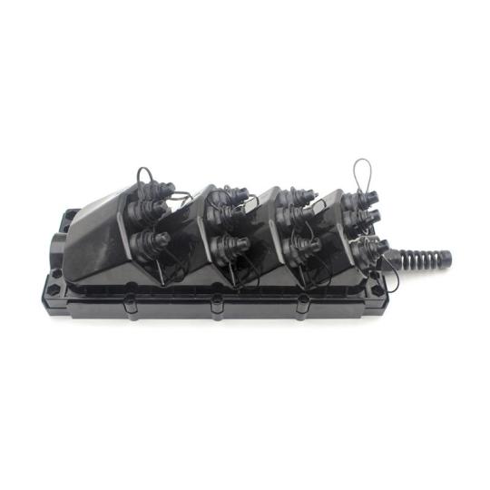
The Multiport Service Terminal Box changes the way fiber networks operate. Network operators choose the 8 port fiber optic MST terminal box with pre-insta for its strong build and easy setup. The FTTH network MST terminal assembly with flexible c and the outdoor rated MST distribution box with hardened a both ensure lasting protection in harsh conditions.
Key Takeaways
The Multiport Service Terminal Box makes fiber network installation faster and easier with pre-terminated cables and flexible mounting options, saving time and reducing errors. Its modular design supports network growth by allowing easy upgrades without major changes, helping operators meet increasing demand smoothly. Built with strong, weather-resistant materials, the box protects connections in harsh outdoor conditions, ensuring long-lasting and reliable network performance.
Key Advantages of Multiport Service Terminal Box
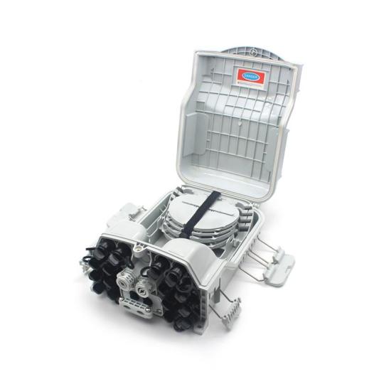
Simplified Installation Process Network operators often face challenges when deploying fiber to the premises. The Multiport Service Terminal Box addresses these issues with a technician-friendly design. Factory-sealed or field assembly options make deployment straightforward. Hardened adapters, fully compatible with OptiTap and other industry standards, allow for rapid plug-and-play connections. The IP68 waterproof rating ensures the box performs well in harsh outdoor environments. Multiple mounting options, such as wall, aerial, pole, pedestal, and handhole, provide flexibility for different installation scenarios. The low-profile design and decreased angle surfaces prevent connector interference during operation. Factory pre-terminated cables eliminate the need for fiber splicing or opening the closure, saving time and reducing errors. Effective cable management reduces clutter and enhances network reliability. Tip: Dowell’s Multiport Service Terminal Box helps technicians complete installations up to 40% faster, lowering operational costs and improving service delivery. Enhanced Network Scalability The Multiport Service Terminal Box supports network growth with ease. Providers can choose from multiple port configurations, including 4, 8, or 12 ports, to match current needs and future expansion. The modular design allows for incremental upgrades without major infrastructure changes. For example, a 12-port terminal with pre-connectorized pigtails and externally mounted hardened adapters enables plug-and-play installation. This approach supports future expansions without re-entering the closure, minimizing disruption. Dowell’s solutions ensure that operators can scale their networks efficiently, meeting growing bandwidth demands and supporting new subscribers as needed. Superior Protection and Durability Feature/Material Description/Benefit Material ABS+PC or polycarbonate plastic for strong mechanical strength and environmental resistance Waterproof Rating IP67 or IP68 for water and dust protection Pulling Force Resistance Withstands long-term pulling forces up to 1200N UV Resistance Complies with SO4892-3 standard for outdoor durability Fire Protection Rating UL94-V0 fire retardant properties Cable Glands Torsion-proof glands relieve stress on cables, preventing fiber breakage Installation Flexibility Suitable for wall, aerial, or pole mounting Assembly Options Factory-sealed or field assembly reduces fiber splicing and environmental exposure Compatibility Works with ODVA, H connector, Mini SC, ODC, PTLC, PTMPO, and more Dowell’s Multiport Service Terminal Box uses these advanced materials and design features to ensure long-lasting performance, even in the most demanding outdoor environments. Cost-Effectiveness The Multiport Service Terminal Box delivers significant cost savings for network operators. Factory pre-terminated cables and plug-and-play adapters reduce installation time and labor costs. The robust, sealed design minimizes maintenance needs and extends product lifespan. Flexible mounting options and modularity lower the need for additional hardware or future upgrades. Effective cable management and technician-friendly features further reduce operational expenses. Note: Dowell’s commitment to quality and innovation ensures that every Multiport Service Terminal Box provides excellent value, helping operators maximize their return on investment.
Multiport Service Terminal Box in Real-World FTTP Deployments
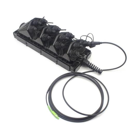
Overcoming Space Constraints Network operators often face limited space in dense urban environments. The Multiport Service Terminal Box provides a compact solution for these challenges. The Mini-MST design supports multiple fiber connections in a single, small unit. Operators can install the box in tight spaces without losing performance. The device allows for high-density connectivity, which is essential in crowded city areas. Dowell offers models with dimensions as small as 210x105x93mm, making them easy to fit in limited locations. Multiple mounting options, such as wall, pole, and aerial, give flexibility for different sites. Miniaturized connectors and universal mounting brackets help technicians install the box quickly, even in hard-to-reach spots. These features help network operators maximize connectivity while using minimal physical space. Environmental Protection for Outdoor Networks Outdoor fiber networks must withstand harsh weather and environmental hazards. The Multiport Service Terminal Box uses rugged, weather-resistant materials to protect connections. Factory-sealed, hardened connectors keep out dirt, moisture, and dust. The enclosure meets IP68 standards, ensuring reliable operation in rain, snow, or extreme temperatures. Dowell designs both underground and aerial models to handle different outdoor conditions. The box resists UV rays and mechanical stress, which extends its service life. These qualities make the terminal box a dependable choice for outdoor FTTP networks. Maintenance and Upgrade Efficiency Efficient maintenance and upgrades are vital for network reliability. The Multiport Service Terminal Box simplifies these tasks with its modular and pre-terminated design. Technicians can add or replace ports without opening the enclosure or splicing fibers. The modular structure allows for quick network expansion with minimal disruption. Dowell’s solution supports rapid troubleshooting, thanks to features like modular fault detection. Compatibility with standard connectors, such as OptiTap and DLX, ensures easy integration with existing infrastructure. These advantages reduce labor time and help operators keep networks running smoothly. Faster Network Rollouts and Reduced Downtime Speed matters in FTTP deployments. The Multiport Service Terminal Box helps operators roll out networks faster and with less downtime. Pre-terminated connectors allow for plug-and-play installation, which saves time and reduces errors. The compact, modular design supports quick upgrades and expansions. Durable materials lower the need for frequent maintenance or replacement. Dowell’s terminal boxes include features for rapid fault detection, so technicians can fix issues quickly. These benefits lead to faster service delivery and improved network uptime. Customer Satisfaction and Long-Term Value Reliable connectivity and easy maintenance lead to higher customer satisfaction. The Multiport Service Terminal Box delivers long-term value for both operators and end-users. The robust design ensures stable performance over many years. Flexible mounting and scalable port options allow operators to meet changing customer needs. Dowell’s commitment to quality means fewer service interruptions and better user experiences. Network operators who choose this solution can build trust with their customers and protect their investment. The Multiport Service Terminal Box delivers unmatched efficiency, reliability, and cost savings for FTTP projects. Feature MST Box Traditional Terminal Installation Efficiency Fast, pre-connectorized Labor-intensive Environmental Protection IP68, UV resistant Less robust Optical Performance Low loss, high reliability Higher loss MST technology supports cost-effective, scalable, and future-proof fiber networks. Operators meet current and future demands with longer transmission distances and flexible expansion. By: Eric Tel: +86 574 27877377 Mb: +86 13857874858 E-mail: [email protected] Youtube: DOWELL Pinterest: DOWELL Facebook: DOWELL Linkedin: DOWELL Read the full article
0 notes
Text
High-Temperature Fiber Optic Cable Solutions for Oil & Gas Pipelines
High-temperature fiber optic cable plays a vital role in oil and gas pipelines. Modern outdoor fiber optic cable and underground fiber optic cable withstand pressures up to 25,000 psi and temperatures up to 347°F. Fiber cable enables real-time, distributed sensing, providing accurate data for pipeline safety and operational efficiency.
Key Takeaways
High-temperature fiber optic cables withstand extreme heat, pressure, and chemicals, enabling safe and efficient monitoring of oil and gas pipelines. Distributed sensing technologies like DTS and DAS provide real-time data to detect leaks, blockages, and other issues early, reducing risks and costs. Choosing the right cable type and coating ensures reliable performance in harsh environments, supporting long-term pipeline safety and operational success.
Fiber Optic Cable Challenges and Requirements in Oil & Gas Pipelines
High Temperatures and Corrosive Environments Oil and gas pipelines expose fiber optic cable to extreme conditions. Operators demand cables that withstand high temperatures, intense pressure, and corrosive chemicals. The following table highlights key performance statistics for cables used in these environments: Parameter / Feature Details / Statistics Operational Temperature Range Exceeds 300°C for downhole sensing fibers Pressure Resistance Up to 25,000 psi in unconventional reservoirs Corrosion Resistance Features Hydrogen-darkening immunity, carbon-coated fibers for hydrogen-induced attenuation Coating Technologies Polyimide, carbon, and fluoride coatings enhance chemical resistance Regulatory Temperature Standards -55°C to 200°C, up to 260°C in aerospace, 175°C for 10 years (Saudi Aramco SMP-9000 spec) Specialized Applications Subsea well monitoring, offshore drilling, petrochemical plants Real-Time Monitoring and Data Accuracy Fiber optic cable enables continuous, real-time monitoring of temperature, pressure, and strain along pipelines. Distributed fiber optic sensing (DFOS) technology detects anomalies and leaks over long distances, supporting immediate intervention and risk mitigation. Operators have used distributed temperature and acoustic sensing to monitor cement integrity, identify cross flow between reservoir zones, and detect plugged inflow control devices. These applications improve productivity and reduce intervention time. Fiber optic cable systems deliver high bandwidth and immunity to electromagnetic interference, ensuring reliable data transmission for remote monitoring. Safety, Reliability, and Compliance Pipeline operators face several challenges when installing and maintaining fiber optic cable systems: Precise sensor installation is critical to avoid disturbing fluid flow. Fiber Bragg Grating sensors become costly for long pipelines. Distributed fiber optic sensors require complex layout designs. The viscoelastic behavior of materials like HDPE complicates measurement accuracy. Distributed Acoustic Sensing methods need advanced signal processing due to variable vibrational signatures. Sensor networks in remote areas require reliable energy supply and add to operational costs. Note: Fiber optic cable solutions help operators meet regulatory standards, enhance safety, and ensure reliable operation in harsh environments.
Fiber Optic Cable Technologies and Solutions for High Temperatures
Distributed Temperature Sensing (DTS) and Distributed Acoustic Sensing (DAS) Distributed Temperature Sensing (DTS) and Distributed Acoustic Sensing (DAS) have transformed pipeline monitoring in the oil and gas industry. DTS uses the scattering of light within a fiber optic cable to measure temperature changes along its entire length. This technology provides continuous, high-resolution thermal profiles, which are essential for detecting leaks, blockages, or abnormal heat signatures in pipelines. Recent advancements in DTS include active methods, such as deploying heat sources to enhance sensitivity. These methods—thermal advection tests, hybrid cable flow logging, and heat pulse tests—offer operators the ability to monitor deep wells with high spatial and temporal resolution. DTS outperforms traditional point sensors, especially in high-temperature environments where accurate, distributed data is critical. DAS, on the other hand, detects acoustic signals and vibrations along the fiber optic cable. This system can monitor thousands of points simultaneously, capturing events such as leaks, flow changes, or unauthorized activities. DAS measures longitudinal strain with directional sensitivity, but its performance depends on factors like fiber orientation and strain coupling efficiency. In high-temperature settings, the mechanical and optical properties of the cable may change, requiring robust design and advanced signal processing. Together, DTS and DAS enable real-time, distributed monitoring, supporting proactive maintenance and rapid response to incidents. Dowell integrates DTS and DAS technologies into its high-temperature fiber optic cable solutions, ensuring reliable performance in the most demanding oil and gas environments. Types of High-Temperature Fiber Optic Cable Selecting the right fiber optic cable for high-temperature applications involves understanding the unique challenges of oil and gas pipelines. Manufacturers design specialty optical fibers to withstand extreme temperatures, corrosive chemicals, and high-pressure hydrogen-rich environments. The following table summarizes common types of high-temperature fiber optic cable and their key features: Cable Type Temperature Range Coating Material Application Area Polyimide-coated Fiber Up to 300°C Polyimide Downhole sensing, well monitoring Carbon-coated Fiber Up to 400°C Carbon, Polyimide Hydrogen-rich environments Metal-coated Fiber Up to 700°C Gold, Aluminum Extreme temperature zones Fluoride Glass Fiber Up to 500°C Fluoride Glass Specialized sensing applications Engineers often deploy these cables in permanent installations, such as well casings, wireline logging cables, and slickline cables. The choice of coating and fiber type depends on the specific temperature, chemical exposure, and mechanical stress expected in the field. Dowell offers a comprehensive portfolio of high-temperature fiber optic cable solutions, tailored to meet the rigorous demands of oil and gas operations. Real-World Applications and Benefits High-temperature fiber optic cable solutions deliver significant benefits across the oil and gas value chain. Operators use distributed sensing technologies—DTS, DAS, and Distributed Vibration Sensing (DVS)—to monitor downhole activities, including hydraulic fracturing, drilling, and production. These systems provide real-time insights into well performance, enabling operators to maximize output and reduce downtime. Specialty fiber optic cables endure harsh conditions, including high temperatures and corrosive chemicals. Distributed sensing enables continuous monitoring for leak detection, flow measurement, and reservoir management. Operators achieve early detection of leaks or blockages, reducing environmental risk and maintenance costs. Fiber optic cable systems replace multiple point sensors, simplifying installation and lowering long-term expenses. Permanent installations in well casings and pipelines ensure reliable, long-term data collection. A comprehensive numerical study, supported by experimental field tests, demonstrates the effectiveness of high-temperature fiber optic cable technologies in monitoring buried high-pressure natural gas pipelines. Researchers used advanced simulation methods and found that cables placed within 100 mm of the pipeline reliably detected leakage-induced temperature changes. The study recommends laying four fiber optic cables evenly around the pipeline circumference for optimal coverage. Experimental results closely matched simulations, confirming the feasibility and accuracy of this approach for high-pressure pipeline leakage detection. Peer-reviewed studies and technical papers document the ongoing innovation in fiber optic sensing technologies. These works validate the reliability and effectiveness of distributed temperature sensing and fiber optic sensors in harsh oilfield environments. Sensuron’s Fiber Optic Temperature Sensing (FOSS) systems, for example, provide continuous, high-resolution temperature monitoring along pipelines, enabling early detection of leaks or blockages. The technology’s chemical inertness and immunity to electromagnetic interference make it ideal for oil and gas applications. Operators benefit from improved efficiency, reduced downtime, and overall cost savings, despite higher initial investments. Companies like Dowell continue to advance fiber optic cable solutions, helping operators achieve safer, more efficient, and more reliable pipeline operations. Selecting the right high-temperature cable ensures safe and efficient pipeline operations. Real-world deployments highlight key benefits: Early threat detection through advanced monitoring systems. Reliable surveillance with integrated audio and video recognition. Improved risk management using predictive models for pipeline failures. Consulting industry experts helps operators achieve compliance and long-term reliability. By: Eric Tel: +86 574 27877377 Mb: +86 13857874858 E-mail: [email protected] Youtube: DOWELL Pinterest: DOWELL Facebook: DOWELL Linkedin: DOWELL Read the full article
0 notes
Text
Comparing Fiber Optic Box and Modem for Modern Internet Needs

A fiber optic box, including both fiber optic box outdoor and fiber optic box indoor models, transforms light signals from fiber optic cable box connections into digital data for internet use. Unlike traditional modems, which process electrical signals, fiber optic technology delivers symmetrical speeds up to 25 Gbps, low latency, and exceptional reliability. Fiber optic pigtail connections further reduce interference and congestion, making fiber the preferred choice for modern, high-speed internet.
Key Takeaways
Fiber optic boxes use light signals to deliver ultra-fast, reliable internet with speeds up to 25 Gbps, far surpassing traditional modems that rely on electrical signals and offer lower speeds. Modems convert digital data into signals suitable for copper or cable lines, enabling internet access but with limitations in speed, distance, and latency compared to fiber optic technology. Choosing fiber optic boxes ensures better security, lower failure rates, and future-proof networks, making them ideal for homes and businesses seeking high performance and scalability.
Fiber Optic Box: What It Is and How It Works
Definition and Main Function A fiber optic box serves as a central hub for managing and protecting fiber optic cables in both residential and commercial networks. This device organizes cable connections, shields fibers from environmental and mechanical damage, and ensures stable, high-speed data transmission. Modern fiber optic boxes use fast connectors and hardened adapters to minimize signal loss and provide quick, reliable connections. Many models feature an IP68 waterproof rating, which guarantees durability in harsh conditions. These boxes also support network scalability, allowing for easy expansion as internet demands grow. Optical splitters inside the box divide incoming signals, enabling one fiber line to serve multiple users or devices efficiently. Fiber optic wall outlets, often integrated with these boxes, connect directly to user devices and deliver ultra-fast data with minimal interference. Note: Fiber optic boxes play a crucial role in future-proofing networks, making them essential for reliable, high-speed internet in homes, businesses, and industrial settings. How a Fiber Optic Box Converts Light Signals A fiber optic box operates by managing the conversion and distribution of light signals that carry data through optical fibers. At the transmission end, devices such as LEDs or laser diodes generate light pulses from electrical signals. These pulses travel through the fiber, guided by total internal reflection, which keeps signal loss extremely low. When the light reaches the fiber optic box, photodiodes convert the light back into electrical signals for use by routers or other network devices. Amplifiers within the system maintain signal strength over long distances, supporting data transmission across tens or even hundreds of kilometers. Multiplexing technologies, such as wavelength division multiplexing (WDM), allow multiple data streams to travel simultaneously on different wavelengths, significantly increasing bandwidth and connectivity speeds. Field tests have shown that these systems can transmit data over 150 kilometers using dozens of wavelengths, demonstrating the effectiveness of fiber optic boxes in supporting high-speed, reliable internet connections.
Modem: Purpose and Operation
Definition and Main Function A modem, short for modulator-demodulator, acts as a vital device in modern internet connectivity. It converts digital data from computers or routers into analog signals that can travel over traditional telephone lines. When data arrives from the internet, the modem reverses this process, changing analog signals back into digital data for use by connected devices. Early modems operated at very low speeds, such as 300 bits per second, but technology has advanced significantly. Today’s broadband modems can reach speeds in the hundreds of megabits per second. Inside, a modem contains a controller, digital-to-analog and analog-to-digital converters, and a data access arrangement. Different types of modems exist, including dial-up, leased-line, broadband, and software-based models. Each type serves specific network needs and physical mediums. Modems remain essential for connecting homes and businesses to the internet, adapting data formats for compatibility with various service types. Modems bridge the gap between a local network and the internet by translating signals from the internet service provider (ISP) into data that devices can use. They support different physical mediums, such as DSL, cable, or fiber, ensuring broad compatibility. Modems enable direct internet access by linking the user’s location to the ISP’s infrastructure. Many modern modems integrate with routers, providing network management and security features. Combined modem-router devices simplify installation and improve reliability for users. Without a modem, direct access to the internet is not possible. How a Modem Processes Electrical Signals Aspect Modems (Modulator-Demodulator) Fiber Optic Boxes (Transmitters and Receivers) Signal Processing Function Modulation and demodulation of digital electrical signals into signals suitable for electrical transmission media. Transmitters convert electrical digital signals into modulated light signals; receivers convert optical signals back to electrical signals. Modulation Method Electrical signal modulation/demodulation (e.g., amplitude or frequency modulation). Electro-optical transduction: modulation of light intensity using LEDs or laser diodes; optical-electrical conversion using photodiodes. Key Components Modulator and demodulator circuits handling electrical signals. Transmitter: LEDs or laser diodes modulated by electrical signals; Receiver: photodiodes (PIN or APD), bias resistors, low-noise pre-amplifiers. Signal Medium Electrical transmission media (e.g., copper wires). Optical fiber cables carrying modulated light signals. Modulation Characteristics Modulates electrical carrier waves to represent digital data (0's and 1's). Modulates light intensity to represent digital data; LEDs provide linear power-current response, laser diodes offer higher power and speed but with nonlinear characteristics. Historical/Design Notes Standardized devices performing modulation/demodulation. Early transmitters were custom designs; now hybrid modules with integrated circuits and optical diodes; design complexity increased with data rates. This table highlights the technical differences between how modems and fiber optic boxes process signals. Modems focus on electrical signals and copper wires, while fiber optic boxes handle light signals and optical fibers.
Fiber Optic Box vs Modem: Key Differences

Technology and Signal Type Fiber optic boxes and modems rely on fundamentally different technologies to transmit data. A fiber optic box manages and organizes fiber cables, ensuring stable connections and minimal signal loss. It does not convert signals but instead acts as a distribution point for light pulses traveling through glass or plastic fibers. In contrast, a modem serves as a bridge between digital devices and the transmission medium. It converts digital electrical signals from computers or routers into analog or optical signals, depending on the network type. Fiber optic technology uses light signals generated by LEDs or laser diodes. These light pulses travel through thin fibers, providing high bandwidth and immunity to electromagnetic interference. Modems, especially those designed for fiber networks, handle the conversion between electrical and optical signals. They use modulation techniques to encode data onto light or electrical carriers. Different modem types, such as E1, V35, RS232, RS422, and RS485, support various data rates and distances, making them suitable for a wide range of network applications. Fiber optic boxes primarily manage cable infrastructure, while modems perform the critical function of signal conversion. This distinction shapes their roles in modern networks. Speed and Performance Speed and performance represent major differentiators between fiber optic boxes and traditional modems. Fiber optic boxes support the transmission of data at extremely high speeds, often reaching up to 25 Gbps or more. The use of light pulses allows for rapid, simultaneous data transfer with very low latency. Fiber optic cables can carry multiple data streams using technologies like wavelength division multiplexing, which further increases capacity. Modems, especially those using copper wires, face limitations in both speed and distance. Electrical signals degrade over long distances, resulting in lower bandwidth and higher latency. Even advanced cable modems rarely match the symmetrical upload and download speeds provided by fiber optic systems. Fiber optic boxes, such as those supplied by Dowell, enable businesses and homes to access ultra-fast internet connections that support streaming, gaming, and cloud applications without interruption. Feature Fiber Optic Box Modem (Copper/Cable) Signal Type Light pulses Electrical signals Max Speed Up to 25 Gbps+ Up to 1 Gbps (typical) Latency Very low Moderate to high Distance 100+ km Limited (few km) Bandwidth Extremely high Moderate Security and Reliability Security and reliability play crucial roles in network infrastructure decisions. Fiber optic boxes offer strong protection against electromagnetic interference, which ensures consistent performance even in environments with high electrical noise. The physical properties of fiber optic cables make them difficult to tap without detection, enhancing data security. Fiber optic systems also experience fewer outages and require less maintenance compared to copper-based networks. However, the hardware design of fiber optic boxes can generate electromagnetic interference (EMI), especially at the street or home level. This EMI may travel through copper wiring and affect sensitive electronic equipment. Companies like Dowell address these concerns by designing fiber optic boxes with improved shielding and robust construction, reducing EMI emissions and enhancing overall reliability. Modems, particularly those with advanced features, allow users to control electromagnetic field (EMF) emissions. Some models enable users to disable Wi-Fi or use low-EMF routers, which can reduce radio frequency exposure in the home. While cable modems may offer more user control over EMF, they cannot match the inherent security and reliability advantages of fiber optic technology. Tip: For users seeking the highest level of security and reliability, fiber optic boxes from reputable manufacturers like Dowell provide a future-proof solution for both home and business networks.
Fiber Optic Box and Modem in Home and Business Setups
Typical Home Network Integration Home networks today often rely on advanced infrastructure to deliver fast, reliable internet to every room. Many households use fiber optic cables, such as PureFiber PRO, to achieve full modem speed throughout the home. This approach eliminates lag and speed drops that commonly occur with traditional CAT cables. Residents frequently install 4-port fiber to Ethernet adapters in living spaces, allowing multiple devices—like Smart TVs, gaming consoles, VOIP phones, and WiFi access points—to connect simultaneously. Some homes daisy-chain these adapters in an electrical closet, creating scalable multi-port switches for future expansion. Network designers often use MPO to LC fiber breakout pigtails, which provide several independent fiber connections per cable. This setup enables separate networks for different purposes, such as work-from-home, smart home automation, or child-safe browsing. Devices with SFP slots and HDMI 2.1 support can connect directly, enabling uncompressed 4K or 8K video streaming. Homeowners benefit from plug-and-play installation, flexible wall plates, and easy cable upgrades. These features ensure high bandwidth, no lag, and future-proofing for evolving digital needs. Business Network Considerations Businesses require robust, scalable, and secure network infrastructures. Organizations often deploy optical network terminals (ONTs) to convert optical signals into electrical signals for use within office networks. ONTs typically offer multiple high-speed Ethernet ports, support for VoIP, and advanced security features like AES encryption. Companies connect ONTs to high-speed routers and Gigabit switches, distributing internet access across departments and devices. A table below summarizes technical integration: Aspect Fiber Optic Boxes (ONTs) Modems Primary Function Optical-to-electrical conversion DSL/cable signal conversion Standards Compliance GPON, XGS-PON DSL/cable standards Port Configuration Multiple high-speed Ethernet ports Ethernet ports Security Features AES encryption, authentication Basic, varies by model Additional Features Battery backup, VoIP, wireless LAN Basic signal conversion Case studies show that organizations like Eurotransplant reduced total cost of ownership by 40% using fiber optic solutions for mission-critical data centers. Service providers, such as Netomnia, have built scalable networks supporting 800G growth with advanced fiber optic technology. These examples highlight the shift from traditional modems to fiber-based solutions, driven by the need for higher bandwidth, reliability, and future-ready infrastructure.
Choosing Between Fiber Optic Box and Modem
Factors to Consider: Speed, Provider, and Compatibility Selecting the right device for internet connectivity requires careful evaluation of several factors. Speed stands as a primary concern for most users. Fiber-based systems deliver much higher bandwidth than cable or DSL alternatives. For example, fiber networks can provide upstream throughput up to 40 Gb/s shared among users, while cable systems using DOCSIS 3.1 typically reach only 1 Gb/s. Latency also differs significantly. Fiber connections often maintain latency below 1.5 milliseconds, even over long distances. Cable systems, on the other hand, may experience additional latency ranging from 2 to 8 milliseconds due to bandwidth allocation processes. Lower latency and higher bandwidth result in smoother experiences for activities such as video conferencing, online gaming, and virtual reality. Providers play a crucial role in device selection. Some carriers supply customer premises equipment, such as modems or routers, at no extra cost. Regulatory guidelines require providers to meet strict performance thresholds. At least 80% of speed measurements must reach 80% of the required speeds, and 95% of latency measurements must remain at or below 100 milliseconds. Providers must also conduct speed and latency tests during peak hours to ensure consistent performance. These requirements help users compare service quality across different providers. Compatibility remains another important factor. Not all devices work seamlessly with every network type. Media converters and modems serve different purposes. Media converters handle simple signal conversion between optical and electrical signals, while modems perform modulation and demodulation for digital communication. Users should verify that their chosen device supports the protocols and interfaces required by their network environment. Factor Fiber-Based Systems Cable/DSL Systems Max Bandwidth Up to 40 Gb/s (shared) Up to 1 Gb/s (DOCSIS 3.1) Typical Latency < 1.5 ms 2–8 ms Provider Role Often supplies ONT/Router Often supplies Modem/Router Compatibility Requires fiber-ready device Requires cable/DSL modem Tip: Always confirm device compatibility with your internet service provider before making a purchase. A fiber optic box manages light-based data with lower failure rates than modems, as shown below: Component Failure Rate (Annual) Fiber-Optic Cable 0.1% per mile Optical Receivers 1% Optical Transmitters 1.5–3% Set Top Terminals / Modems 7%

Most users benefit from the speed, reliability, and future-proof design of a fiber optic box. By: Eric Tel: +86 574 27877377 Mb: +86 13857874858 E-mail: [email protected] Youtube: DOWELL Pinterest: DOWELL Facebook: DOWELL Linkedin: DOWELL Read the full article
0 notes
Text
Choosing Between Indoor and Outdoor Fiber Optic Boxes: A Buyer’s Checklist

Selecting the correct fiber optic cable box depends on the conditions at the installation site. Outdoor Fiber Optic Boxes protect connections from rain, dust, or impact. A fiber optic box outdoor resists harsh weather, while a fiber optic box indoor suits clean, climate-controlled rooms.
Key Takeaways
Choose fiber optic boxes based on the installation environment to protect cables from weather, dust, and damage or to ensure easy access and fire safety indoors. Check for durability, proper sealing, and compliance with safety standards to keep your network reliable and safe over time. Plan for capacity and future growth by selecting boxes that support easy expansion and good cable management to reduce downtime and maintenance costs.
Quick Comparison: Indoor vs. Outdoor Fiber Optic Boxes

Features Table: Indoor vs. Outdoor Fiber Optic Boxes Feature Indoor Fiber Optic Boxes Outdoor Fiber Optic Boxes Environment Climate-controlled, clean Exposed to weather, dust, impact Material Lightweight plastic or metal Heavy-duty, weatherproof materials Protection Level Basic dust and tamper resistance High resistance to water, UV, and vandalism Mounting Options Wall, rack, or ceiling Pole, wall, underground Fire Rating Often fire-rated May include UV and corrosion resistance Accessibility Easy access for maintenance Secured, sometimes lockable Typical Applications Offices, server rooms, data centers Building exteriors, utility poles, outdoor enclosures Key Differences at a Glance Outdoor Fiber Optic Boxes withstand harsh environments. They use robust materials and seals to block water, dust, and UV rays. Indoor boxes focus on easy access and cable management. They suit spaces where temperature and humidity stay stable. Outdoor Fiber Optic Boxes often feature lockable covers and reinforced construction. These features deter tampering and protect sensitive connections. Indoor models prioritize compact design and fire safety. They integrate well with existing IT infrastructure. Tip: Always match the box type to the installation site. Using the wrong type can lead to costly repairs or network downtime.
Key Factors When Choosing Outdoor Fiber Optic Boxes or Indoor Options
Installation Environment and Exposure Selecting the right fiber optic box starts with a careful assessment of the installation environment. Outdoor Fiber Optic Boxes must withstand direct exposure to rain, dust, temperature swings, and even chemical contaminants. Manufacturers use weatherproof materials like UV-resistant plastics or aluminum to protect sensitive connections. Proper sealing with high-quality gaskets prevents moisture infiltration, which can degrade fiber optic performance. In contrast, indoor fiber optic boxes operate in climate-controlled spaces, so lighter and more cost-effective plastics are suitable. Site preparation also plays a role. Installers should avoid areas prone to moisture or extreme temperatures and ensure ventilation to prevent overheating. Regular maintenance, such as inspecting seals and cleaning fiber ends, helps maintain optimal performance. Tip: Outdoor boxes should withstand thermal cycling and chemical exposure for long-term reliability. Outdoor boxes require high IP ratings and robust materials. Indoor boxes can use lighter materials due to reduced environmental risks. Proper sealing and site selection are critical for both types. Protection, Durability, and Weather Resistance Protection and durability define the difference between indoor and outdoor solutions. Outdoor Fiber Optic Boxes use heavy-duty materials and reinforced construction to resist physical impact and environmental hazards. For example, dual jacket cables provide an extra layer of defense against moisture, temperature changes, and mechanical stress. This enhanced protection reduces the risk of signal degradation and physical damage, ensuring reliable performance in harsh conditions. Indoor boxes, while less rugged, still offer basic dust and tamper resistance. The choice of material and construction should match the expected hazards at the installation site. Location, Accessibility, and Ease of Installation Location and accessibility influence both installation and ongoing maintenance. Installers often face challenges when placing fiber optic boxes in cluttered or hard-to-reach locations. Poor accessibility can complicate repairs and increase downtime. Best practices recommend selecting locations that avoid moisture and physical impact, ensuring secure connections, and labeling cables clearly for easier maintenance. Hard-to-reach or cluttered sites can cause future maintenance problems. Poor labeling complicates repairs, especially in complex environments. Different mounting options (wall, pole, rack) suit various environments and accessibility needs. Quality sealing and material selection remain critical for outdoor or harsh environments. Easy installation reduces errors and network downtime. Capacity, Expandability, and Fiber Management Capacity and expandability determine how well a fiber optic box supports current and future network needs. Effective fiber management practices, validated by industry standards like EIA/TIA 568 and ISO 11801, ensure reliable performance. Installers should use proper cable handling techniques, maintain appropriate pulling tension, and separate fiber from heavy copper cables. Support structures must comply with standards, and clear labeling helps with organization. Accessories such as hook and loop cable ties keep installations neat and reduce cable damage. These practices maintain cable performance and simplify future upgrades or repairs. Note: Cable management tools and accessories help keep fiber optic installations organized, supporting long-term reliability. Compliance, Fire Rating, and Safety Standards Compliance with fire ratings and safety standards is essential, especially for indoor installations. Fiber optic cables must meet specific fire ratings such as OFNP, OFNR, and OFN, depending on their application area. These ratings exist to prevent fire propagation and reduce toxic smoke, which can pose serious risks in confined spaces. For example, Low Smoke Zero Halogen (LSZH) jackets minimize hazardous emissions during a fire. The National Electrical Code (NEC) mandates different fire ratings for various building areas to protect occupants and property. NEC Fire Rating Code Cable Type Description Fire Resistance Level Typical Application Areas OFNP Optic Fiber Non-conductive Plenum Highest (1) Ventilation ducts, plenum or return air pressurization systems (air circulation spaces) OFCP Optic Fiber Conductive Plenum Highest (1) Same as OFNP OFNR Optic Fiber Non-conductive Riser Medium (2) Vertical backbone cabling (risers, shafts between floors) OFCR Optic Fiber Conductive Riser Medium (2) Same as OFNR OFNG Optic Fiber Non-conductive General-Purpose Lower (3) General purpose, horizontal cabling areas OFCG Optic Fiber Conductive General-Purpose Lower (3) Same as OFNG OFN Optic Fiber Non-conductive Lowest (4) General purpose OFC Optic Fiber Conductive Lowest (4) General purpose

Plenum-rated cables (OFNP/OFCP) offer the highest fire resistance and are required in air circulation spaces to prevent fire hazards and toxic smoke spread.
Buyer’s Checklist for Indoor and Outdoor Fiber Optic Boxes
Assess Your Installation Site and Environmental Risks A thorough assessment of the installation site forms the foundation of any fiber optic project. Environmental risks vary widely between indoor and outdoor locations. For example, a project in Yellowstone National Park required careful planning to avoid environmental impact, including burying fiber in conduit and relocating cell towers. Exposure to harsh weather, temperature swings, and moisture can degrade cables, leading to signal loss. Construction activities, wildlife interference, and corrosion in humid or salty environments also threaten cable integrity. Regular inspection and maintenance help detect vulnerabilities early, minimizing service disruptions. Tip: Use protective enclosures and schedule routine checks to safeguard your network investment. Determine Required Protection and Durability Protection and durability requirements depend on the environment. Outdoor Fiber Optic Boxes must withstand rain, dust, and temperature fluctuations. Manufacturers use weatherproof materials like stainless steel or specialized plastics. Proper sealing prevents moisture ingress, which can damage cables. Products such as the FieldSmart® Fiber Delivery Point Wall Box meet NEMA 4 standards, demonstrating suitability for challenging conditions. Fiber optic boxes with enhanced weather resistance use waterproof enclosures, gel-filled tubes, and corrosion-resistant materials. These features ensure consistent high-speed connectivity and long-term reliability, even in high-risk areas. Dowell offers a range of Outdoor Fiber Optic Boxes designed for maximum durability and protection, supporting network reliability in demanding environments. Evaluate Capacity and Future Expansion Needs Capacity planning ensures the fiber optic box supports both current and future network demands. Persistent coverage gaps, supply chain strains, and rapid growth in data centers highlight the importance of scalable solutions. Modular, pre-terminated assemblies and smaller form-factor connectors allow for higher fiber density without increasing space requirements. The global fiber management systems market is expanding rapidly, driven by rising bandwidth needs and the proliferation of IoT devices. Flexible, scalable systems help organizations adapt to future growth with minimal downtime. Note: Choose fiber optic boxes that allow for easy expansion and support advanced management features. Check Compatibility with Fiber Cables and Infrastructure Compatibility with existing fiber cables and infrastructure is critical. Installation methods differ by environment. Outdoor cables may be direct buried, aerial, or installed in conduit, while indoor cables often use raceways or cable trays. Following manufacturer recommendations for pulling tension, bend radius, and handling prevents fiber damage. Hardware such as racks, cabinets, and splice panels should match the installation environment. Dowell provides comprehensive solutions that ensure seamless integration with both new and legacy infrastructure, reducing installation errors and supporting long-term performance. Review Compliance and Building Code Requirements Compliance with building codes and industry standards ensures safety and network integrity. Indoor fiber optic boxes must meet standards such as TIA-568 and ISO/IEC 11801, which govern design, installation, and maintenance. Proper cable management and high-quality materials are essential for reliable indoor networks. Outdoor installations require adherence to local codes and environmental regulations, including weatherproofing, burial depth, and protection against UV exposure and physical damage. Institutions like UA Little Rock enforce strict compliance, requiring detailed documentation and testing to guarantee infrastructure reliability. Always verify that your chosen fiber optic box meets all relevant codes and standards for your region. Match Features to Indoor or Outdoor Fiber Optic Boxes Selecting the right features depends on the installation environment. Outdoor Fiber Optic Boxes need robust construction, weatherproof seals, and enhanced security features such as lockable covers. Indoor boxes should prioritize compact design, fire safety, and easy access for maintenance. Use sealed splice closures outdoors and patch panels or wall-mounted boxes indoors. Dowell’s product line includes both indoor and outdoor options, allowing buyers to match features precisely to their site requirements. Balance Budget with Required Features Budget considerations play a significant role in the selection process. High deployment costs, regulatory hurdles, and skilled labor shortages can impact project timelines and expenses. Innovations such as microtrenching and modular assemblies help reduce costs and speed up installation. Federal and state funding programs may support fiber expansion in underserved areas. Buyers should balance initial investment with long-term reliability, protection, and scalability. Investing in quality fiber optic boxes from trusted suppliers like Dowell ensures value and performance over the life of your network.
Common Scenarios for Indoor and Outdoor Fiber Optic Boxes

Typical Indoor Applications Fiber optic boxes serve a wide range of indoor environments. Offices, data centers, and server rooms often require secure and organized cable management. These locations benefit from wall-mounted or rack-mounted boxes that keep fiber connections safe from accidental damage and unauthorized access. Educational institutions and hospitals use indoor fiber optic boxes to support reliable internet and communication networks. In these settings, technicians can easily access and maintain connections due to the controlled environment. Compact designs and fire-rated materials help these boxes blend into existing infrastructure while meeting safety standards. Note: Indoor fiber optic boxes simplify network upgrades and routine maintenance, reducing downtime in mission-critical facilities. Typical Outdoor Fiber Optic Boxes Use Cases Outdoor Fiber Optic Boxes play a crucial role in environments exposed to weather, physical impact, and temperature extremes. Utility poles, building exteriors, and underground installations all require robust protection for fiber connections. Field experiments have shown that optical fiber sensors, when placed in watertight boxes and reinforced soil, can withstand dynamic and seismic loads. These sensors maintained accuracy even under accelerations up to 100 g, proving the reliability of outdoor installations in harsh geotechnical conditions. In ecological monitoring, fiber-optic distributed temperature sensing systems have delivered precise temperature data across multiple stream sites. These systems provided superior coverage and accuracy, supporting sensitive applications like fisheries habitat selection. Outdoor Fiber Optic Boxes enabled these advanced technologies to function reliably, even in challenging environments with fluctuating temperatures and moisture. Utility companies use outdoor boxes for network distribution in rural and urban areas. Environmental agencies deploy fiber optic systems for real-time monitoring in remote locations. Construction projects rely on outdoor boxes to protect connections during site development. The installation environment determines the best fiber optic box for any project. Selecting boxes with high reliability metrics, such as strong weather resistance and low insertion loss, reduces downtime and maintenance costs. Using the buyer’s checklist helps organizations achieve long-term network performance, safety, and value. By: Lynn Tel: +86 574 86100572#8816 Whatsapp: +86 15168592711 E-mail: [email protected] Youtube: JINGYI Facebook: JINGYI Read the full article
0 notes
Text
How Armored Fiber Cables Reduce Environmental Damage in Remote Deployments

Armored fiber cables protect sensitive environments in remote areas. Their tough design reduces ground disturbance and resists hazards from wildlife. Studies show that direct connections using armored fiber optic cable keep attenuation under 1.5 dB, outperforming multimode fiber cable in reliability. Fiber cable installations benefit from lower connector loss and improved durability. Parameter Value Attenuation (direct connection) ≤ 1.5 dB OSNR margin (live network) 19 dB Connector loss (multi-connector) 2 dB
Key Takeaways
Armored fiber cables protect sensitive environments by reducing the need for deep digging and heavy equipment during installation, which limits soil and vegetation disturbance. These cables resist damage from wildlife, weather, and physical stress, leading to fewer repairs and less disruption to remote ecosystems. Their strong design and long lifespan reduce waste and maintenance visits, supporting sustainable and reliable network infrastructure in harsh and remote areas.
Armored Fiber Cables: Protective Features and Environmental Benefits

Structure and Durability of Armored Fiber Cables Armored fiber cables use advanced engineering to deliver strong protection in harsh environments. Their structure includes a glass fiber core, waterproof and heat-resistant cladding, and a tough outer jacket. Manufacturers like Dowell use ruggedized military-grade materials such as 302 stainless steel, aramid yarn, and special polymer jackets. These materials help the cables resist crushing, abrasion, and pulling. Note: Dowell’s armored fiber cables are trusted by defense contractors and the US military. These cables maintain network transmission even during natural disasters or severe crush loads. A variety of technical features ensure durability: Feature Description IP68 Outdoor Waterproof Rating 100% waterproof for outdoor and indoor use Temperature Resistance Reliable from -40°C to +85°C Chemical Resistance Jackets resist oils, solvents, and corrosive substances Rodent Proofing Steel tubes prevent rodent damage Crush Resistance Withstands high compressive forces Vibration & Mechanical Stress Reinforced for continuous vibration and stress Repeated Bending Bend-insensitive fibers keep signals strong Lockable IP68 Bayonet Connectors Secure, tamper-resistant outdoor connections Engineering studies show that armored fiber cables can handle pull strengths over 100 pounds. Their design allows for quick and reliable field termination, even in wet or high-temperature locations. This makes them ideal for industries like oil and gas, aerospace, and critical data centers. Reduced Ground Disturbance During Installation Armored fiber cables help protect the environment during installation. Their tough design means installers do not need to dig deep trenches or use heavy equipment. This reduces the amount of soil and vegetation that gets disturbed. Installers can lay these cables directly on the ground or just below the surface. The cables’ flexibility allows them to follow natural land contours, avoiding sensitive habitats. Dowell’s armored fiber cables support micro-trenching and direct burial, which further limits ground disruption. Read the full article
0 notes
Text
What You Need to Know About Fiber Optic Box Uses

A fiber optic box manages and protects fiber optic connections, serving as a critical point for termination, splicing, and distribution. Fiber optic cable box designs support high bandwidth, long-distance transmission, and secure data flow. The fiber optic box outdoor and fiber optic box indoor types ensure reliable performance in diverse environments. Aspect Details / Numerical Values Tensile Strength Minimum 7000 kg/cm² Attenuation Rate Approximately 0.2 dB/km for fiber optic cables Fiber Core Counts in Boxes Commonly 8, 16, or 24 cores per distribution box Bandwidth Capacity Measured in terabits per second (Tbps), very high bandwidth Transmission Distance Long-distance transmission with low signal loss Immunity to Interference Not affected by electromagnetic interference Security Difficult to tap without detection, ensuring secure data Fiber optic boxes use specialized splicing and termination methods to maintain system reliability and protect sensitive connections.
Key Takeaways
Fiber optic boxes organize and protect fiber cables, ensuring strong, fast, and secure data connections in various environments. Proper installation and cable management prevent damage and signal loss, making networks more reliable and easier to maintain. Regular maintenance and careful handling extend the life of fiber optic systems and help avoid costly network problems.
Fiber Optic Box Functions and Features

Cable Management in a Fiber Optic Box Effective cable management stands as a core function of any fiber optic box. Organized internal layouts, including splice trays and connectors, minimize clutter and prevent tangling. This structure supports smooth data transmission and reduces the risk of signal loss. Distribution boxes shield delicate fiber optic cables from environmental contaminants such as moisture and dirt, which extends the network’s lifespan. Sturdy enclosures provide mechanical protection against impacts and vibrations, ensuring cables remain secure even in challenging environments. Technicians benefit from easy access designs that allow for quick inspection, maintenance, and repair. Wall-mounted and pole-mounted options offer convenient access for both indoor and outdoor installations. Maintaining proper bend radius within the box prevents signal attenuation and fiber breakage, which reduces operating costs and network downtime. Clear cable routing paths simplify installation and enable safe retrofits. These features collectively support network reliability and efficiency. Tip: Organized cable management not only preserves network integrity but also simplifies future upgrades and maintenance. Splicing and Protection in Fiber Optic Box Applications Splicing and protection represent essential features in fiber optic box applications. Fusion splicing, a common method, delivers minimal insertion loss and superior signal integrity. Industry standards from organizations such as the National Institute of Standards and Technology (NIST) confirm that fusion splicing results in lower loss compared to mechanical splicing. This method supports longer transmission distances, which is critical for large-scale networks. Fiber optic boxes provide robust environmental protection, especially for outdoor deployments. Specialized enclosures and sealing techniques prevent moisture ingress and physical damage. Modular designs and enhanced cable management improve operational efficiency and security. Pre-terminated fiber solutions further reduce on-site splicing needs, increasing installation speed and reliability. These features ensure that fiber optic boxes maintain signal quality and network performance, even in demanding conditions. Feature Category Examples / Details Network Performance Enhancement Basic Functions Mechanical fixing of cables, fiber and connector protection, flexible deployment and testing, storage with minimum bending radius Maintains signal integrity, prevents fiber damage, allows easy maintenance and testing, and prevents signal loss due to bending Distribution and Signal Routing with Fiber Optic Box Distribution and signal routing play a pivotal role in the performance of fiber optic networks. A fiber optic box serves as a centralized point for organizing and managing fiber cables, splices, and connectors. Adapter panels inside the box provide termination points for fiber connections, which facilitates easy rearrangement, repair, or replacement of circuits. Stacking or mounting panels in data centers improves accessibility and speeds up maintenance tasks. Field studies show that environmental conditions, installation methods, and professional techniques such as fusion splicing and high-quality connectors are critical for ensuring low signal loss and long-term reliability. Proper routing and physical layout, combined with rigorous testing methods like Optical Time-Domain Reflectometry (OTDR), verify signal integrity and performance. In distributed networks, the physical infrastructure and routing of signals through fiber transmission lines directly impact network robustness and data processing success rates. Specification Details Product Type Fiber Optic Hardware Application Data Center Fiber Density per Unit 384 Housing Type EDGE8® Fixed Number of Panels 48 Dimensions (H x W x D) 241 mm x 527 mm x 527 mm Standards Compliance RoHS 2011/65/EU Shipping Weight 18 kg This table highlights the advanced technical features of high-density fiber optic boxes, such as the Corning EDGE8 Housing FX, which supports up to 384 fibers per unit and complies with environmental standards. These capabilities demonstrate the importance of proper distribution and signal routing in supporting scalable, reliable, and high-performance networks.
Types of Fiber Optic Box and Their Uses
A variety of fiber optic box types exist to meet different installation needs and environmental challenges. The table below highlights the main categories and their typical applications: Type of Fiber Optic Distribution Box Installation Context Usage and Features Wall-Mounted Indoor, mounted on walls or vertical surfaces Compact design for limited indoor space; organizes and terminates fiber optic cables neatly. Rack-Mounted Data centers, telecom rooms in 19-inch racks Supports high-density termination; centralized cable management for multiple fiber connections. Outdoor Outdoor environments with harsh conditions Weather-resistant materials; protects cables in FTTH and other outdoor deployments. Dome-Shaped Aerial or underground installations Dome enclosure protects against moisture, dust; used for robust, reliable fiber optic networks. Wall-Mounted Fiber Optic Box Wall-mounted fiber optic boxes offer a compact solution for indoor environments where space is limited. Their design allows for neat organization and secure termination of fiber optic cables. These boxes reduce clutter and protect cables from physical damage, which minimizes signal loss. Many network installers choose wall-mounted options for their scalability and flexibility. They support high-density connections and provide ultra-fast data transmission, making them ideal for both residential and commercial settings. Their resistance to electromagnetic interference and minimal signal loss ensure reliable, future-proof network infrastructure. Rack-Mounted Fiber Optic Box Rack-mounted fiber optic boxes play a critical role in data centers and telecom rooms. They maximize space efficiency by utilizing vertical rack space and support centralized cable management for multiple fiber connections. Key operational advantages include: Improved airflow and cooling through vented panels and open-frame designs Enhanced security with locking mechanisms on doors and side panels Simplified maintenance due to ergonomic mounting heights Effective cable management with designated pathways and labeling However, rack-mounted solutions have weight capacity limits and require proper ventilation to prevent overheating. Regular maintenance and ergonomic planning help maintain operational efficiency and equipment safety. Outdoor Fiber Optic Box Outdoor fiber optic boxes protect network connections in harsh environments. Manufacturers use weather-resistant materials to shield cables from moisture, dust, and temperature extremes. These boxes are essential for fiber-to-the-home (FTTH) deployments and other outdoor applications. Their robust construction ensures reliable performance and long-term durability, even in challenging conditions.
Practical Fiber Optic Box Uses, Installation, and Maintenance
Fiber Optic Box in Homes, Offices, Data Centers, and Telecom Fiber optic boxes serve as essential components in a wide range of environments. In residential settings, they function as fiber access points for FTTH projects, delivering high-speed internet directly to homes. Offices and commercial buildings rely on these boxes to support optical fiber local area networks, ensuring stable and fast connectivity for daily operations. Data centers use fiber optic boxes to manage internal fiber networks within server and switch rooms, optimizing performance and organization. Telecom companies deploy these boxes as centralized management areas in base stations and node stations, supporting large-scale communication networks. Dowell provides solutions tailored for each of these scenarios, ensuring reliable performance and easy integration. Residential: Fiber access points in FTTH projects Office: Supports optical fiber LANs in commercial buildings Data Center: Manages internal fiber networks in server rooms Telecom: Centralized management in base stations and node stations Fiber Optic Box Installation Best Practices Proper installation ensures long-term reliability and performance. Industry guidelines recommend the following steps: Plan installations carefully and handle all components with care to avoid damage. Maintain the correct bend radius to prevent hidden fiber damage. Route cables precisely and avoid exceeding pulling tension. Test connections using optical power measurements, insertion loss, and OTDR traces. Clean fiber ends and connectors with specialized kits. Follow manufacturer recommendations, such as those provided by Dowell. Inspect for environmental damage, including moisture or mechanical stress. Keep detailed records of cable routes, test results, and faults. Schedule routine maintenance checks, especially for mission-critical networks. 10. Use test results to monitor network health and detect degradation. Installation Aspect Key Guidelines and Metrics Material Selection Choose materials for the environment; metal for outdoors, plastic for indoors. Site Preparation Select accessible, ventilated locations; minimize cable length. Mounting Procedures Securely mount and label; inspect and clean cables before connection. Cable Management Avoid excess tension; use cable ties and conduits; label for identification. Connection Techniques Clean and inspect fiber ends; use flexible connectors; respect bend radius limits. Testing Protocols Visual inspection, power meter tests, OTDR for faults. Success Metrics Signal quality, regular maintenance, adherence to installation limits. Fiber Optic Box Maintenance Tips Routine maintenance extends the life of fiber optic systems. Technicians should inspect connections regularly to detect contamination or damage. Cleaning with recommended materials maintains connection quality. Standardized procedures help prevent accidental damage during upkeep. Accurate documentation of inspection and cleaning activities supports effective troubleshooting. Using proper tools and safety measures protects both the fiber optic components and technicians. Maintaining organized technical records and proactive schedules ensures optimal performance. Quality assurance and safety protocols, including safe disposal of glass shards, reduce risks. Dowell recommends ongoing training for technicians and a well-organized work environment to minimize mishandling and improve maintenance efficiency. Tip: Proactive maintenance and detailed documentation help prevent costly network outages and support long-term reliability. Fiber optic networks depend on careful planning and regular maintenance to achieve reliable performance. Scientific studies show that accurate system modeling and clean connections reduce failures and support high data rates. Technicians who follow best practices in selection, installation, and care help networks run efficiently and avoid costly downtime. By: Consult Tel: +86 574 27877377 Mb: +86 13857874858 E-mail: [email protected] Youtube: DOWELL Pinterest: DOWELL Facebook: DOWELL Linkedin: DOWELL Read the full article
0 notes
Text
ADSS Cable Clamps: Ensuring Reliability in High-Voltage Power Line Installations

ADSS cable clamps play a crucial role in high-voltage power line installations. Their advanced gripping mechanisms, such as those in an ADSS suspension clamp or adss cable tension clamp, prevent cable slippage and damage. The table below shows how selecting the right ADSS clamp improves reliability and lifespan for different span lengths and cable diameters: Clamp Type Work Suspension Load (kN) Recommended Span Length (m) Cable Diameter Range (mm) Reinforced Rod DN-1.5(3) 1.5 Up to 50 4 - 9 No DN-3(5) 3 Up to 50 4 - 9 No SGR-500 Less than 10 Up to 200 10 - 20.9 Yes SGR-700 Less than 70 Up to 500 14 - 20.9 Yes
Key Takeaways
Choosing the right ADSS cable clamp type and size ensures strong support and long-lasting performance for high-voltage power lines. Proper installation and regular maintenance keep cables secure, prevent damage, and improve safety in all weather conditions. Using high-quality materials and designs helps resist corrosion, electrical faults, and environmental challenges, reducing repair costs.
ADSS Cable Clamps and Their Role in High-Voltage Installations

Definition and Core Functions of ADSS Cable Clamps ADSS Cable Clamps serve as essential components in high-voltage power line systems. These clamps provide mechanical support, electrical insulation, and strain relief for cables. Their main functions include: Supporting cables to distribute weight evenly and prevent sagging. Insulating cables from supporting structures to avoid electrical contact. Allowing for cable movement due to wind or temperature changes, reducing stress. Securing cables firmly to prevent detachment under load. Protecting against corrosion with durable materials. Maintaining proper cable alignment for efficient power transmission. Note: Dowell manufactures ADSS Cable Clamps using high-quality materials like aluminum and stainless steel, ensuring long-term reliability and corrosion resistance in demanding environments. Main Types: Tension, Suspension, and Downlead Clamps ADSS Cable Clamps come in several types, each designed for specific roles: Tension Clamps: These clamps anchor cables at endpoints or mid-span, holding them under significant mechanical load. Suspension Clamps: Used to support cables at intermediate points, they allow for controlled movement and reduce vibration. Downlead Clamps: These guide cables down poles or towers, maintaining a safe bend radius and protecting cable integrity. Each type addresses unique installation challenges, ensuring cables remain secure and undamaged. Critical Applications in Power Line Systems ADSS Cable Clamps play a vital role in high-voltage installations. Their non-conductive design provides excellent electrical insulation, making them safe for use near energized lines. The clamps withstand harsh conditions, including wind, ice, and temperature extremes. Case studies show that these clamps maintain a firm grip and resist corrosion in coastal and urban environments. Their modular design simplifies installation, reducing labor costs and downtime. Dowell’s ADSS Cable Clamps offer reliable performance in both urban and rural aerial networks, supporting the stability and safety of modern power transmission systems.
Key Features of ADSS Cable Clamps for Reliability
Essential Components and Materials Manufacturers design ADSS Cable Clamps with several critical components. Each part serves a specific function to ensure the clamp performs reliably in high-voltage environments. The main components include: Clamp Body: Usually made from high-strength aluminum alloy, this part provides the main structural support. Gripping Inserts: These inserts, often crafted from thermoplastic or elastomeric materials, grip the cable securely without causing damage. Bolts and Fasteners: Stainless steel bolts and nuts hold the assembly together and resist corrosion. Protective Liners: Some clamps feature liners that cushion the cable and prevent abrasion. Dowell selects premium materials for every component. The company uses corrosion-resistant metals and UV-stable polymers. These choices extend the service life of the clamps and reduce maintenance needs. Note: High-quality materials not only improve mechanical strength but also enhance safety in harsh outdoor conditions. Gripping Mechanisms and Strain Relief The gripping mechanism forms the heart of every ADSS Cable Clamp. Engineers design these mechanisms to distribute mechanical loads evenly along the cable. This approach prevents localized stress points that could lead to cable damage or failure. Wedge Action: Many clamps use a wedge system. As the cable pulls, the wedge tightens, increasing grip strength. Helical Rods: Some designs incorporate helical rods that wrap around the cable, providing both grip and flexibility. Elastomeric Pads: These pads conform to the cable’s surface, increasing friction and reducing slippage. Strain relief features protect the cable from excessive tension. By absorbing and distributing forces, the clamp reduces the risk of breakage during storms or high winds. Dowell’s engineering team tests each design to ensure optimal strain relief for a wide range of cable diameters and installation scenarios. Corrosion Protection and Environmental Resistance ADSS Cable Clamps must withstand a variety of environmental challenges. Exposure to rain, salt spray, UV radiation, and temperature extremes can degrade materials over time. Reliable clamps feature several protective measures: Anodized Aluminum: This finish resists oxidation and maintains structural integrity. Stainless Steel Hardware: Bolts and nuts made from stainless steel prevent rust and ensure long-term performance. UV-Resistant Polymers: These materials do not crack or weaken under sunlight. Dowell subjects its clamps to rigorous environmental testing. The company simulates years of exposure to harsh conditions, ensuring each product meets industry standards for durability. Tip: Regular inspection and maintenance further extend the lifespan of clamps in challenging environments. Electrical Insulation and Safe Distance Maintenance Safety remains a top priority in high-voltage power line installations. ADSS Cable Clamps provide electrical insulation to prevent accidental contact between the cable and supporting structures. This insulation reduces the risk of electrical faults and ensures compliance with safety regulations. Non-Conductive Materials: Many clamps use polymer inserts or coatings to isolate the cable electrically. Proper Spacing: The clamp design maintains a safe distance between the cable and metal hardware, minimizing the chance of arcing. Dowell’s clamps meet strict insulation requirements. The company’s products help utilities maintain safe, reliable power transmission even in densely populated or high-risk areas.
Selecting and Using ADSS Cable Clamps Effectively
Matching Clamp Type to Installation Requirements Selecting the correct clamp type ensures safe and reliable cable support. Engineers assess factors such as span length, cable diameter, and environmental conditions. Tension clamps work best for anchoring cables at endpoints or where high mechanical loads occur. Suspension clamps provide support at intermediate points, allowing for controlled movement. Downlead clamps guide cables along poles, maintaining proper alignment. Dowell offers a comprehensive range of ADSS Cable Clamps, each designed for specific installation scenarios. Their technical team assists clients in choosing the right product for every project. Installation Best Practices for ADSS Cable Clamps Proper installation maximizes performance and extends service life. Installers should follow manufacturer guidelines closely. They must clean all contact surfaces before assembly. Torque specifications for bolts and fasteners require strict adherence. Installers should check for correct cable alignment and ensure that clamps do not pinch or deform the cable. Dowell recommends periodic inspections after installation to identify early signs of wear or loosening. Tip: Use only approved tools and accessories during installation to avoid damaging the clamp or cable. Common Mistakes and How to Avoid Them Mistakes during installation can compromise system reliability. Common errors include using the wrong clamp type, over-tightening bolts, or neglecting environmental factors. Installers sometimes skip regular maintenance checks, which increases the risk of failure. To avoid these issues, teams should receive proper training and consult Dowell’s technical documentation. Keeping detailed records of installation and maintenance activities helps ensure long-term reliability for ADSS Cable Clamps. Selecting the right cable clamp improves safety and reliability in high-voltage power line systems. Proper installation provides mechanical stability and electrical insulation. High-quality products help companies achieve efficient and trouble-free power transmission. Investing in reliable solutions protects infrastructure and reduces maintenance costs. By: Consult Tel: +86 574 27877377 Mb: +86 13857874858 E-mail: [email protected] Youtube: DOWELL Pinterest: DOWELL Facebook: DOWELL Linkedin: DOWELL Read the full article
0 notes
Text
What Makes the 2.0×5.0mm SC UPC Cable Patch Cord Ideal for FTTH in 2025

The 2.0×5.0mm SC APC FTTH Drop Cable Patch Cord delivers outstanding reliability and performance for FTTH networks. With a low insertion loss of ≤0.2 dB and high return loss values, this SC APC FTTH Drop Cable Assembly ensures stable, high-speed data transmission. Growing FTTH deployments worldwide highlight the need for robust solutions like the SC APC Pre-connectorized FTTH Fiber Optic Drop Cab and Drop Cable Patch Cord. Parameter Typical Value Insertion Loss ≤ 0.2 dB Return Loss ≥ 50 dB (UPC), ≥ 60 dB (APC) Durability ≥ 1000 mating cycles
Key Takeaways
The 2.0×5.0mm SC UPC Cable Patch Cord offers a slim, flexible design that makes installation easier in tight spaces and helps maintain strong, stable connections for fast internet. This patch cord delivers low signal loss and high return loss, ensuring reliable, high-speed data transmission even in challenging environments. It meets strict international standards and certifications, guaranteeing broad compatibility, long-term durability, and consistent performance for modern FTTH networks.
Cable Patch Cord Design and Performance

Compact 2.0×5.0mm Form Factor The 2.0×5.0mm form factor offers a compact and flexible solution for modern fiber optic installations. Installers often face challenges when routing cables through tight spaces and complex pathways in FTTH environments. The slim profile of this Cable Patch Cord allows for easy handling and efficient cable management, reducing the risk of damage during installation. Multiple strands of fine copper wire inside the cord provide softness and flexibility, making it suitable for both indoor and outdoor deployments. The design supports single-fiber connections, which simplifies network expansion and maintenance. Note: Dowell engineers have optimized the sheath and internal structure to ensure the cable withstands frequent bending and handling, maintaining performance over time. SC UPC Connector Precision SC UPC connectors deliver high precision and reliability in fiber optic networks. The push-pull locking mechanism ensures a secure connection, minimizing the risk of accidental disconnection. This connector type is widely used in routers, switches, and patch panels due to its ease of use and stable performance. The zirconia ceramic ferrule inside each connector guarantees accurate alignment of the fiber core, which is essential for minimizing signal loss. Dowell utilizes advanced polishing and inspection techniques, including 3D interferometry, to achieve optimal endface geometry and cleanliness. These measures help maintain low back-reflection and consistent optical performance. SC connectors are easy to plug and unplug, supporting quick installation. The design supports high-density network environments, making it ideal for FTTH applications. Each connector undergoes rigorous endface inspection to prevent contamination and ensure long-term reliability. Low Insertion Loss and High Return Loss Performance metrics such as insertion loss and return loss define the quality of a fiber optic connection. The 2.0×5.0mm SC UPC Cable Patch Cord achieves a typical insertion loss of ≤0.20 dB, which surpasses many competitor products that offer insertion loss values up to 0.3 dB. High return loss values, with UPC connectors reaching ≥50 dB and APC connectors achieving ≥60 dB, further enhance signal integrity by reducing back-reflection. Connector Type Maximum Insertion Loss Minimum Return Loss UPC 0.3 - 0.5 dB -50 dB or greater APC 0.3 - 0.5 dB -60 dB or greater Dowell’s Cable Patch Cord consistently maintains these low insertion loss and high return loss figures, even under varying temperature and humidity conditions. This stability ensures reliable data transmission for high-speed FTTH networks.

Enhanced Signal Stability for FTTH Signal stability remains a top priority in FTTH deployments. Dowell subjects every Cable Patch Cord to comprehensive component testing, including frequency, insertion loss, return loss, and crosstalk measurements. Each cord undergoes 100% factory testing, with detailed reports verifying performance. These tests confirm that the patch cord maintains excellent signal quality, avoiding data packet loss or corruption, even in demanding environments such as data centers. Testing includes insertion and return loss measurements, attenuation checks, and endface inspections after polishing. Physical tests simulate environmental stresses like heat, moisture, and mechanical impact. Strict quality management ensures consistent performance from production to field installation. The result is a Cable Patch Cord that delivers stable, high-speed data transmission, supporting the bandwidth demands of modern FTTH networks. Dowell’s commitment to quality and innovation positions this product as a leading choice for reliable fiber optic connectivity in 2025.
Cable Patch Cord Installation, Compatibility, and Future-Proofing

Easy Handling and Routing in FTTH Environments Installers often face complex environments when deploying fiber-to-the-home networks. The 2.0×5.0mm SC UPC Cable Patch Cord addresses these challenges with a compact, flexible design that simplifies routing through tight spaces and crowded conduits. Dowell engineers have optimized the sheath and internal structure to withstand frequent bending and handling, ensuring the cable maintains performance over time. Pre-terminated fiber optic drop cables have proven effective in FTTH deployments by reducing installation time, improving quality, and minimizing on-site errors. Urban and rural case studies show that pre-terminated cables enable faster deployment, cost savings, and fewer maintenance issues. Proper cable routing, including the use of cable trays and hooks, supports efficient installation. Correct tensioning prevents fiber damage and extends service life. Trained personnel and thorough documentation help maintain long-term network performance. Passive Optical Networks (PONs) further simplify installation by using fewer active components and serving multiple customers over a single fiber. This architectural simplicity, combined with durable, weather-resistant cables, leads to fewer repairs and lower maintenance costs. Broad Device and Network Compatibility Dowell’s Cable Patch Cord demonstrates broad compatibility with a wide range of network hardware. The product carries UL listings for the U.S. and Canada, as well as GSA approval, confirming compliance with strict safety and quality standards. These certifications make the patch cord suitable for diverse and demanding network environments. Patch cords from Dowell undergo rigorous channel and permanent link testing to verify performance. They meet RoHS, ETL, UL, and ISO standards, ensuring reliable operation in both legacy and modern networks. High-purity oxygen-free copper cores and advanced shielding options contribute to stable conductivity and minimize signal loss. Network deployment analytics highlight the benefits of compatibility in high-density device environments. Distributed architectures, such as Remote PHY and Remote MAC-PHY, support efficient operations and better management of space, power, and cooling. Fiber optic patch cords with bend-insensitive fibers and ultra-low loss technology maintain network performance even in dense deployments. Factory termination and clean connectors ensure seamless integration with upgraded infrastructures. Third-party testing confirms that high-quality, properly tested patch cords ensure optimal network performance. Dowell’s products consistently meet or exceed TIA/EIA-568-B performance requirements, providing assurance of interoperability with OEM channels and backward compatibility with legacy systems. Compliance with Latest FTTH Standards Dowell’s commitment to quality is evident in the Cable Patch Cord’s adherence to the latest FTTH standards. Fiber patch cord quality tests reference IEC technical standards, which specify critical parameters such as fiber end face geometry and performance metrics. These parameters ensure that optical connectors maintain signal integrity and minimize loss. Standard/Certification Scope EIA/TIA 568, 569, 570, 606, 607 Commercial and residential telecommunications cabling, pathways, administration, bonding, grounding, and testing ISO/IEC 11801, 14763-1/2/3, IEC 61935-1 International standards for copper and fiber optic cabling systems ISO9001, UL, ETL, CE, RoHS, CPR Product quality, safety, environmental, and fire resistance certifications Certification modes depend on fire rating classes, with factory audits and annual product sampling required for higher ratings. Testing standards such as ISO 1716, EN 50399, and EN 61034-2 are conducted in official EU notified body labs. Compliance declarations enable CE marking for products meeting EN 50575, and factory production control reviews ensure ongoing compliance. Durability and Long-Term Reliability Dowell’s Cable Patch Cord stands out for its durability and long-term reliability in FTTH networks. The product undergoes rigorous testing protocols, including end-to-end attenuation tests, Optical Time-Domain Reflectometer (OTDR) analysis, and connector loss measurements. These tests ensure minimal signal degradation and verify fiber integrity. Testing Method Purpose End-to-end attenuation tests Measure total signal loss affecting speed and bandwidth, ensuring minimal degradation. OTDR Detect faults and verify fiber integrity, crucial for long-term performance. Connector loss measurement Ensure connections maintain optimal signal quality, preventing signal degradation. Dowell’s patch cords maintain signal quality even after 500 plug-ins and pull-outs, demonstrating exceptional mechanical strength. The helically stranded cable design reduces bending stress, while crush-resistant jacketing withstands environmental challenges such as moisture, abrasion, and temperature fluctuations. Regular inspections and advanced monitoring software help maintain network integrity over time. Tip: Durable, weather-proof fiber optic cables contribute to fewer repairs and less frequent maintenance, supporting reliable FTTH service for years. The 2.0×5.0mm SC UPC Cable Patch Cord stands out for FTTH in 2025. The LinkIQ tester confirms high-speed connectivity from 10 Mb/s to 10 Gb/s, validating performance. The Long Lines case study demonstrates long-term value and customer satisfaction in FTTH projects. Metric HC-Series Cable Ribbon Cable Bit Error Rate Error-free Degrades Mechanical Strength High Lower Installation Speed Fast Slower By: Consult Tel: +86 574 27877377 Mb: +86 13857874858 E-mail: [email protected] Youtube: DOWELL Pinterest: DOWELL Facebook: DOWELL Linkedin: DOWELL Read the full article
0 notes