#Optimized OFDM
Explore tagged Tumblr posts
Visit Tumblr Blog
Explore Tumblr blogs with no restrictions, modern design and the best experience.
Last Seen Tumblr Blogs


film-vf-en-eaux-tres-troubles-fr
[VoIr] En eaux très troubles | en Streaming Vostfr (FR) Complet
1 post

Fun Fact
Tumblr was attacked by a cross-site scripting worm deployed by the Internet troll group GNAA on Dec 3, 2012.
Text
Unique MATLAB based projects for final year Students
Hello students!!! Are you searching for MATLAB based projects, then what are you waiting for??? Now Takeoff Edu group gives more innovative projects, which is helpful for your Academic year.
MATLAB projects involving both theory and practical work are perfect for discovering, theorizing and adding new solutions and approaches to the ones that are already known in fields different from engineering and science to finance and so on. Matlab is a powerful and by way of many modules and kits, Matlab equips researchers, engineers and developers to quickly solve complicated problems.
In engineering, MATLAB is very efficient in the designing, analysis, and modelling of engineering systems including, among other, control systems, signal processing, image processing as well as video processing. Projects in this area may range from mapping of image enhancement, innovation in robot controllers to simulating of systems dynamics for predictive maintenance.

The below MATLAAB based projects Titles are taken from “Takeoff Edu Group”:
Latest:
COMPARATIVE STUDY OF LINEAR PRECODING TECHNIQUES.
Average Information based Spectrum Sensing for Cognitive Radio.
MIMO Spectrum Sensing for Cognitive Radio-Based Internet of Things.
Deep Learning-based Sum Data Rate and Energy Efficiency Optimization for MIMO-NOMA Systems.
On Performance of Underwater Wireless Optical Communications under Turbulence.
Trendy:
Power Allocation for Non-Orthogonal mm Wave Systems with Mixed-Traffic
No coherent Backscatter Communications over Ambient OFDM Signals
A Novel Pilot Decontamination on Uplink Massive MIMO
Arena Function A Framework for Computing Capacity Bounds in Wireless Networks
Resource Allocation for Wireless-Powered IOT Networks with Short Packet Communication
Standard:
Application of MIMO-OFDM Technology in UAV Communication Network
Interference Alignment Techniques for MIMO
Capacity of Wireless Networks with Directed Energy Links in the Presence of Obstacles
Leaky Least Mean Square (LLMS) Algorithm for Channel Estimation in BPSK-QPSK-PSK MIMO-OFDM System
Subcarrier Allocation and Precoder Design for Energy Efficient MIMO-OFDMA Downlink Systems
Finally, MATLAB-based projects are the essential breeding ground for innovation, allowing professionals to answer and address the issues they face as well as to not only touch on but to change boundaries of what is possible in their respective areas.
Takeoff Edu Group provides all kind of projects with new ideas and best guidance for engineering students. Here we also support students to upgrade their knowledge and skills.
#MATLAB Projects#Deep learning Projects#Final Year projects#Mini MATLAB Projects#ECE Projects#Image Processing Projects.
0 notes
Text
The Technology Behind Digital Data Transmissions Over Cell Phone Networks
In today's interconnected world, the ability to transmit digital data over cell phone networks has become an integral part of our daily lives. Whether it's browsing the internet, streaming media, or sending messages, our reliance on mobile data continues to grow. But have you ever wondered about the technology that enables these digital data transmissions? In this article, we will explore the primary technology used to provide digital data transmissions over cell phone networks.
## Cellular Technology: The Backbone of Mobile Data
Cellular technology forms the foundation of mobile data transmissions. It refers to the use of various generations of mobile network standards that facilitate wireless communication between mobile devices and network infrastructure. These standards include GSM (Global System for Mobile Communications), CDMA (Code Division Multiple Access), and LTE (Long-Term Evolution).
### GSM - Global System for Mobile Communications
GSM is a widely adopted cellular technology standard used globally. It employs time division multiple access (TDMA) to divide the frequency spectrum into time slots. This division allows multiple users to share the same frequency by allocating unique time slots to each user. GSM technology enables voice calls, text messaging, and low-speed data transfer.
### CDMA - Code Division Multiple Access
CDMA is another cellular technology standard that uses spread spectrum techniques to allocate unique codes to different users, allowing simultaneous transmissions over the same frequency band. Unlike GSM, CDMA does not divide the frequency spectrum into time slots. Instead, it assigns a unique code to each communication channel. CDMA technology is known for its enhanced capacity and improved call quality.
### LTE - Long-Term Evolution
LTE, also referred to as 4G, is an advanced cellular technology that offers higher data rates, improved capacity, and lower latency compared to its predecessors. LTE utilizes orthogonal frequency-division multiplexing (OFDM), a modulation technique that divides the available frequency spectrum into multiple smaller subcarriers. These subcarriers are orthogonal to each other, enabling simultaneous transmission of multiple data streams. LTE also incorporates multiple-input and multiple-output (MIMO) technology, which uses multiple antennas at both the transmitter and receiver ends to increase data throughput and network capacity.
## Advantages of LTE Technology
Compared to previous generations, LTE technology provides several advantages that enhance data transmissions over cell phone networks:
### Higher Data Rates
The use of OFDM allows LTE to achieve higher data rates by efficiently transmitting data in both the time and frequency domains. With larger bandwidth and increased spectral efficiency, LTE can support faster download and upload speeds, enabling seamless streaming, rapid content downloads, and smooth browsing experiences.
### Improved Spectral Efficiency
By utilizing advanced signal processing techniques such as adaptive modulation and coding, HARQ, and channel-dependent scheduling, LTE maximizes spectral efficiency. Adaptive modulation and coding dynamically adjust the modulation scheme and error correction coding based on channel conditions, optimizing data rates while maintaining reliable transmission. HARQ combines error detection and retransmission techniques, minimizing data packet loss and improving overall efficiency. Channel-dependent scheduling optimizes the allocation of radio resources, ensuring efficient utilization of available bandwidth.
### Reduced Latency
LTE technology significantly reduces network latency, enabling real-time applications such as online gaming, video conferencing, and IoT (Internet of Things) connectivity. Low latency ensures minimal delay in data transmission, enhancing user experience and supporting time-sensitive applications.
### Enhanced Network Capacity
With the implementation of MIMO technology, LTE enhances network capacity by transmitting multiple data streams simultaneously over the same frequency band. This spatial multiplexing technique allows for higher data throughput, improved coverage, and increased user capacity within a cell.
## The Evolution Continues: 5G Networks
As technology progresses, the cellular landscape continues to evolve. The advent of 5G, the fifth generation of cellular networks, introduces even more significant advancements. 5G networks promise ultra-fast speeds, ultra-low latency, and massive connectivity to support emerging technologies like autonomous vehicles, augmented reality, and smart cities.
5G utilizes advanced technologies such as millimeter waves, massive MIMO, beamforming, and network slicing to achieve unprecedented performance. These technologies enable faster data rates, improved network capacity, and enhanced reliability, unlocking a whole new realm of possibilities for mobile data transmissions.
Click here and get 100$ for smartphone users survey
## Conclusion
The technology behind digital data transmissions over cell phone networks has come a long way since the early days of mobile communication. Cellular technologies like GSM, CDMA, and LTE have revolutionized the way we connect, communicate, and consume data on our mobile devices. With higher data rates, improved spectral efficiency, reduced latency, and enhanced network capacity, these technologies have paved the way for seamless mobile experiences. As we look to the future, the ongoing evolution of cellular technology, particularly with the advent of 5G, promises to unlock even more incredible possibilities for the world of digital data transmissions.

0 notes
Link
0 notes
Text
3GPP NR Specifications
Introduction The initial specifications enabled non-standalone 5G radio systems integrated with previous generation i.e LTE networks. This scope of Release-15 expands to cover standalone 5G with the development of a new radio system i.e 5G NR(New Radio). Rel-15 and Rel-16 constitute the basis of 5G technology. The ultra-lean design of NR enhances the network energy performance and reduces…

View On WordPress
#5g#5g3gpp#5gcore#5gnetwork#5gnr#5gran#5gtechnology#3GPP NR Specifications#5G MU-MIMO#career aggregation#dual connectivity#dynamic spectrum sharing#Optimized OFDM
0 notes
Text
A Well Developed 5G Network for Better Communication
It is the 5th generation mobile network. It is a newest global wireless standard after these generations 1G, 2G, 3G, and 4G networks. It was known as new kind of network that is constructed to connect virtually everyone and the whole thing together including machines, objects, and devices. This is meant to deliver higher multi-Gbps peak data speeds of a 5G wireless technology, ultra-low latency, more dependability, massive network capacity, increased availability, and a more uniform user experience to more users. With a better performance and improved efficiency empower new user occurrences and connects new productions. There's no one owned the 5G, but there are a lot of companies inside the smartphone ecosystem that are supplying to bringing 5G to life. Qualcomm played as one of the major roles in creating the numerous foundational technologies that initiative the industry forward and make up 5G, the next wireless standard.
This is based on OFDM (Orthogonal frequency-division multiplexing), this is their way of moderating a digital signal throughout several not the same channels to reduce meddling. 5G uses 5G NR air interface together with OFDM principles. 5G also customs wider bandwidth technologies such as sub-6 GHz and mmWave. It has a similar to 4G LTE both can operates based on the same mobile networking principles.
Pros of 5G network
I. Lower perceived latency: 5G network was the one who can help to increase the speed for data transfer since its latency is about one millisecond, this can connect and capacity of devices at real time and avoid experiencing lag and interruption every day.
II. Increase the data rate: 5G network has 10Gbps with a hundred times faster than the usual maximum of 100Mbps rate in 4G network. Assist on the spot where you are on the area that has a better capacity for 5G network
III. There is an improvement in broadband: They can scope 3 spectrum bands that can develop mobile broadband, that has an impact for the society or economy in a lot of sectors in the industries.
IV. It provides excellent opportunities for remote device control: Getting a lower latency can is helping a lot of small machinery pieces, with the predictive hardware maintenance, energy consumption optimization, asset tracking, intelligent logistics, and industrial management.
V. It provides a new wireless technology in eHealth: remote recovery development is now possible with 5G wireless technology and an easy way to safety and health monitoring systems.
VI. There is a new Internet of things solution: more network devices will become energy efficient. It will permit all the smart devices like homes, saving time on doing chores and essential developing all the introduces automation, enhances operations, and ensures security.
VII. There is immersive gaming: this is a game changer that allows online gaming with optimal user experience and an opportunity to augment virtual reality.
How to know if your smartphone is 5G Compatible? ---------------------------------------------------------
Does it searchable in the internet? Yes, this step is the easiest way to see if your desire smartphone is really 5G compatible is to search you can use a Google up its specs online. These enhancements are the biggest database of smartphones specifications in the whole world. You can see and check put the information of your desire or current smartphone model and scroll through entire specifications. Underneath the Network field, post if 5G bands are already listed or not.
Is it on the settings of the phone? Yes, This another way to check if your smartphone supports the 5G or not just check in the phone settings. Presuming it’s an Android phone, you can to the settings, check the Network & internet go to Mobile Network, take a look on the Preferred Network. This should be shown all the Mobile Network technologies supported such as 2G, 3G, 4G and 5G. if you successfully see a logo there and shown up listed, then your smartphone capable to have a 5G Network.
Is there a 5G Logo? Not all the smartphones have a 5G logo, especially those released from the year of 2020, it easily a way to help to identify it by verifying the model and specs online if it's 5G capable.
There’s a lot of benefits and reasons why 5G are more better than the previous network generation, we just need or simply be vigilant on what are we doing know what are the most important thing we need to learn every single day. Technology is unpredicted sometimes it give a lot of development in our daily lives, you just need to be responsible in every choices that you made.
Get to know more about 5G
Visit our website at https://www.nextelle.net.au
0 notes
Text
TMYTEK Introduces 5G mmWave Beamformers and Frequency Converters for the FR2 Spectrum
TMYTEK Introduces 5G mmWave Beamformers and Frequency Converters for the FR2 Spectrum TMY Technology has introduced a series of 5G mmWave beamformers and frequency converters that support both 28 GHz and 39 GHz with the full 5G FR2 spectrum coverage for antenna and algorithm developers. In particular, academic researchers and antenna module makers can benefit from these innovative products to speed up their R&D progress 20X faster in the advanced mmWave solutions.
"5G is no doubt the driving force for the next-generation transformation and we are more than excited to see and support the boost of new 5G opportunities in the global market with our growing mmWave product offerings to speed up FR2 technology development and application faster than ever," said Ethan Lin, VP and Co-founder of TMYTEK. "Our BBox 5G series and UD Box 5G series not only support 28 GHz in the FR2 frequency band for most countries in the world but also cover 39 GHz that is currently available in the US, Canada, Australia and China markets. By solving the challenge of mmWave propagation and understanding the pain points in beamforming implementation, our team continues optimizing product design to ensure the cutting-edge performance of 5G mmWave development products. Meanwhile, we have added dynamic thermal compensation for constant RF performance and enabled SPI control by FPGA/SDR to achieve a short beam switching time of hundreds nanosecond to fulfill the 3GPP beam management requirement."
Covering FR2 bands n257, n258, n259, n260 and n261, the most common 5G mmWave and satellite communication spectrum, the latest 5G version of beamformers and frequency converters designed by TMYTEK allow developers and researchers to perform mmWave applications development and test on extended frequency bands.
The use case of the University of Hawaii at Manoa has successfully developed a 5G NR sensing prototype system for contactless COVID-19 testing by using TMYTEK's mmWave products. With two of TMYTEK's beamformers, BBox, as the OFDM transmitter (Tx) and receiver (Rx), and one UD Box as a frequency up and down converter, researchers can set up a mmWave radar environment quickly and focus on algorithm development, to successfully developed an accurate, safe, and contactless COVID-19 testing system.
TMYTEK's latest BBox 5G beamformers integrate all active circuits, including Power Amplifiers (PA), Low Noise Amplifiers (LNA), Phase Shifters, and T/R switches in one box to make a complete RF front-end for 5G mmWave applications. Moreover, the detachable antenna design offers excellent flexibility for easy attachment for any array antenna. UD Box 5G, an ultra-broadband frequency up and down converter radio frequency cover up to 44 GHz. TMYTEK's in-house designed GUI and API provide individual control of phase and amplitude of each channel in BBox and configure the frequencies in UD Box, allowing antenna designers, system integrators and algorithm developers to complete beamforming and conduct testing from different angles for various mmWave deployment scenarios.
0 notes
Text
5G O-RAN: Open RAN Network Software
5G O-RAN: Open RAN Network Software
5G radio, improves spectral efficiency while offering unrivaled network capacity. 5G New Radio technology is based on adaptable OFDM waveforms and multiple access techniques that have been optimized for a wide range of 5G services, applications, and deployment scenarios. Various 3GPP standards outline 5G (NR) functions, with the first phase finished in Rel-15 and the second phase completed in…

View On WordPress
0 notes
Text
TMYTEK Introduces 5G mmWave Beamformers and Frequency Converters for the FR2 Spectrum
TMYTEK Introduces 5G mmWave Beamformers and Frequency Converters for the FR2 Spectrum TMY Technology has introduced a series of 5G mmWave beamformers and frequency converters that support both 28 GHz and 39 GHz with the full 5G FR2 spectrum coverage for antenna and algorithm developers. In particular, academic researchers and antenna module makers can benefit from these innovative products to speed up their R&D progress 20X faster in the advanced mmWave solutions.
"5G is no doubt the driving force for the next-generation transformation and we are more than excited to see and support the boost of new 5G opportunities in the global market with our growing mmWave product offerings to speed up FR2 technology development and application faster than ever," said Ethan Lin, VP and Co-founder of TMYTEK. "Our BBox 5G series and UD Box 5G series not only support 28 GHz in the FR2 frequency band for most countries in the world but also cover 39 GHz that is currently available in the US, Canada, Australia and China markets. By solving the challenge of mmWave propagation and understanding the pain points in beamforming implementation, our team continues optimizing product design to ensure the cutting-edge performance of 5G mmWave development products. Meanwhile, we have added dynamic thermal compensation for constant RF performance and enabled SPI control by FPGA/SDR to achieve a short beam switching time of hundreds nanosecond to fulfill the 3GPP beam management requirement."
Covering FR2 bands n257, n258, n259, n260 and n261, the most common 5G mmWave and satellite communication spectrum, the latest 5G version of beamformers and frequency converters designed by TMYTEK allow developers and researchers to perform mmWave applications development and test on extended frequency bands.
The use case of the University of Hawaii at Manoa has successfully developed a 5G NR sensing prototype system for contactless COVID-19 testing by using TMYTEK's mmWave products. With two of TMYTEK's beamformers, BBox, as the OFDM transmitter (Tx) and receiver (Rx), and one UD Box as a frequency up and down converter, researchers can set up a mmWave radar environment quickly and focus on algorithm development, to successfully developed an accurate, safe, and contactless COVID-19 testing system.
TMYTEK's latest BBox 5G beamformers integrate all active circuits, including Power Amplifiers (PA), Low Noise Amplifiers (LNA), Phase Shifters, and T/R switches in one box to make a complete RF front-end for 5G mmWave applications. Moreover, the detachable antenna design offers excellent flexibility for easy attachment for any array antenna. UD Box 5G, an ultra-broadband frequency up and down converter radio frequency cover up to 44 GHz. TMYTEK's in-house designed GUI and API provide individual control of phase and amplitude of each channel in BBox and configure the frequencies in UD Box, allowing antenna designers, system integrators and algorithm developers to complete beamforming and conduct testing from different angles for various mmWave deployment scenarios.
1 note
·
View note
Text
IJWMT Vol. 9, No. 6, Nov. 2019
Load Balancing in Cloud Computing Using Hungarian Algorithm
Mohammad Irfan Bala, Mohammad Ahsan Chishti
Design of Adder Using Quantum Cellular Automata
K.Sundara Rao, Mrudula Singamsetti, Vuyyuru Tejaswi
BER Performance Optimization of the SFBC-OFDM System for Economical Receiver Design with Imperfect Channel Estimation
Md. Jakaria Rahimi,Md. Shaikh Abrar Kabir, Azhar Niaz, Md. Jahidul Islam,Oli Lowna Baroi
Compact Ultra-wideband Bandpass Filter with Wide Fractional Bandwidth and High Skirt Selectivity
Lei Bai, Yi-qi Zhuang, Zhi-bin Zeng
Development of a Path-loss Prediction Model Using Adaptive Neuro-fuzzy Inference System
Adeyemo Z.K, Olawuyi T.O, Oseni O.F, Ojo S.I
0 notes
Text

IJCNIS Vol. 11, No. 10, Oct. 2019
An Efficiency Optimization for Network Intrusion Detection System
Mahmoud M. Sakr, Medhat A. Tawfeeq, Ashraf B. El-Sisi
PAPR Reduction in OFDM System Using Clipping and Filtering Methods Based on CCDF
Tanvir Ul Haque, Sharif Hossen
Privacy and Security Concerns in Electronic Commerce Websites in Ghana: A Survey Study
Issah Baako, Sayibu Umar, Prosper Gidisu
Security Policy Modelling in the Mobile Agent System
Hassan RAZOUKI
Network Architectures, Challenges, Security Attacks, Research Domains and Research Methodologies in VANET: A Survey
Amit Kumar Goyal, Gaurav Agarwal, Arun Kumar Tripathi
An TPM Based Approach for Generation of Secret Key
Sanjay Kr. Pal, Shubham Mishra
0 notes
Photo


*Got some extreme LiFi-ness happening in the new scholarly paper here.
http://www.sciencedirect.com/science/article/pii/S2405428317300151?via%3Dihub#fig0004
(…)
Conclusion
In this paper we have shown that there has been a clear trend in wireless communications to use ever higher frequencies. This is a consequence of the limited availability of RF spectrum in the lower frequency bands and at the same time an exponential growth in wireless data traffic we have been witnessing during the last decade. This growth will continue. It is, therefore, inevitable that other spectrum than the RF spectrum must be used for future wireless communication systems. We, therefore, forecast a paradigm shift in wireless communications when moving from mm-wave communication to nm-wave communication which consequently involves light – i.e., LiFi. There has been significant research in physical layer technologies for LiFi during the past 15 years and data rates have increased from a few Mbps in around 2002 to 8 Gbps from a single LED in 2016. In the last five years there has been increasing research in LiFi networking techniques such as multiuser access, interference mitigation and mobility support, and in parallel LiFi products have been developed which have enabled wireless networking with light. Therefore, LiFi has become a reality and this technology is here to stay for a long time.
Acknowledgements
Prof Haas acknowledges support from the EPSRC under Established Career Fellowship grantEP/K008757/1.
References
[1]
H. Haas Wireless data from every light bulb TED Global (Aug-2011)
[2]
H. Haas, L. Yin, Y. Wang, C. Chen What is LiFi? IEEE J. Light. Technol., 34 (6) (Mar. 2016), pp. 1533-1544
[3]
P.J. Winzer, D.T. Neilson From scaling disparities to integrated parallelism: a decathlon for a decade IEEE J. Light. Technol., 35 (5) (Mar. 2017), pp. 1099-1115
[4]
F. Boccardi, R.W. Heath, A. Lozano, T.L. Marzetta, P. Popovski Five disruptive technology directions for 5G IEEE Commun. Mag., 52 (2) (Feb. 2014), pp. 74-80
[5]
M.S. Islim, et al.Towards 10 Gb/s orthogonal frequency division multiplexing-based visible light communication using a GaN violet micro-LED Photon. Res., 5 (2) (2017), pp. A35-A43
[6]
D. Tsonev, S. Videv, H. Haas Towards a 100 Gb/s visible light wireless access network Opt. Express, 23 (2) (2015), pp. 1627-1637
[7]
I. Stefan, H. Burchardt, H. Haas Area spectral efficiency performance comparison between VLC and RF femtocell networks IEEE International Conference on Communications (ICC) (2013), pp. 3825-3829
[8]
Y. Liang, H. Haas Physical-Layer Security in Multiuser Visible Light Communication Networks IEEE J. Sel. Areas Commun. (2017)
[9]
W. Ni, R.P. Liu, B. Collings, X. Wang Indoor Cooperative Small Cells over Ethernet IEEE Commun. Mag., 51 (9) (2013), pp. 100-107
[10]
A. Papaioannou, F.N. Pavlidou Evaluation of Power Line Communication Equipment in Home Networks IEEE Syst. J., 3 (3) (2009), pp. 288-294
[11]
H. Haas High-speed wireless networking using visible lightSPIE Newsroom (2013)
[12]
V.H. MacDonald The cellular concept Bell Syst. Tech. J., 58 (1) (Jan. 1979), pp. 15-43
[13]
A. Goldsmith Wireless Communications Cambridge University Press (2005)
[14]
D. Tsonev, S. Videv, H. Haas Unlocking spectral efficiency in intensity modulation and direct detection systems IEEE J. Sel. Areas Commun. (99) (2015), p. 1
[15]
H. Elgala, T.D.C. Little SEE-OFDM: Spectral and energy efficient OFDM for optical IM/DD systems IEEE 25th Annual International Symposium on Personal, Indoor, and Mobile Radio Communication (PIMRC), 2014 (2014), pp. 851-855
[16]
H. Ma, L. Lampe, S. Hranilovic Robust MMSE linear precoding for visible light communication broadcasting systems 2013 IEEE Globecom Workshops (GC Wkshps) (2013), pp. 1081-1086
[17]
A. Tzanakaki, et al. Wireless-Optical Network Convergence: Enabling the 5G Architecture to Support Operational and End-User Services IEEE Commun. Mag., 55 (10) (2017), pp. 184-192
[18]
B. Ghimire, H. Haas Self-organising interference coordination in optical wireless networks EURASIP J. Wirel. Commun. Netw., 1 (131) (Apr. 2012)
[19]
C. Chen, V.S.,D. Tsonev, H. Haas Fractional frequency reuse in DCO-OFDM-based optical attocell networks J. Light. Technol., 33 (19) (Oct. 2015), pp. 3986-4000
[20]
Y. Wang, S. Videv, H. Haas Dynamic load balancing with handover in hybrid Li-Fi and Wi-Fi networks Proc. IEEE 25th International Symposium on Personal Indoor and Mobile Radio Communications (PIMRC) (2014), pp. 548-552
[21]
M. Ayyash, et al. Coexistence of WiFi and LiFi toward 5G: concepts, opportunities, and challenges IEEE Commun. Mag., 54 (2) (Feb. 2016), pp. 64-71
[22]
I. Stefan, H. Haas Analysis of Optimal Placement of LED Arrays for Visible Light Communication Proc. of IEEE Vehicular Technology Conference (VTC Spring) (2013), p. 5
[23]
P. Patel, J. Holtzmann Analysis of a Simple Successive Interference Cancellation Scheme in DS/CDMA System IEEE J. Sel. Areas Commun., 12 (5) (1994), pp. 796-807
[24]
M.Z. Afgani, H. Haas, H. Elgala, D. Knipp Visible light communication using OFDM Proc. IEEE 2nd Int. Conf. Testbeds Res. Infrastructures Develop. Netw. Communities(2006), pp. 129-134
[25]
K.D. Langer, J. Vucic Optical Wireless Indoor Networks: Recent Implementation Efforts Proc. European Conference on Optical Communication (ECOC) (2010), p. 6
[26]
Y. Li, M. Safari, R. Henderson, H. Haas Optical OFDM with single-photon avalanche diode IEEE Photonics Technol. Lett., 27 (9) (2015), pp. 943-946
[27]
M.S. Islim, M. Safari, S. Videv, H. Haas A Proof-of-Concept of Outdoor Visible Light Communications in the presence of Sunlight LED professional Symposium - Expo, 2016 (2016)
[28]
Z. Wang, D. Tsonev, S. Videv, H. Haas On the design of a solar-panel receiver for optical wireless communications with simultaneous energy harvesting IEEE J. Sel. Areas Commun., 33 (8) (Aug. 2015), pp. 1612-1623
© 2017 Published by Elsevier B.V.
1 note
·
View note
Text
EVOLUTION OF 1G TO 5G
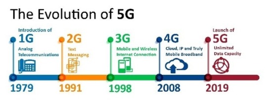
1G to 5G evolution
1G
The original of cell systems - or their 1G arrangement named by the up and coming age of compasses presented - was propelled by Nippon Telegraph and Telephone (NTT) in Tokyo in 1979. In 1984, NTT had propelled 1G to be open to the entirety of Japan.
In 1983, the US propelled the main 1G activity and DynaTAC. Motorola got one of the main 'cell' phones utilized in the United States. Different nations like Canada and the UK propelled their own 1G arrange a couple of years after the fact.
Nonetheless, 1G innovation expands the quantity of shortcomings. Poor inclusion and low solid quality. There is no wandering help between different administrators and, on account of various frameworks on various recurrence ranges, there is no similarity between frameworks. More regrettable than every one of that, calls can't be scrambled, so anybody utilizing a radio scanner can get calls.
At an expense of $ 2,995 ($ 9,660 for every cash today), DynaTAC still figured out how to gather 20 million worldwide clients that thrived in 1990. There is no turning around; Success 1G. Get 2G.
Its basic features are:
Speed-2.4 kbps
Allows voice calls in 1 country
Use analog signal.
Poor voice quality
Poor battery life
Large phone size
Limited capacity
Poor handoff reliability
Poor security
Offered very low level of spectrum efficiency
2G
Second Generation (2G), 2G refers to the second generation based on GSM and was emerged in late 1980s. It uses digital signals for voice transmission. Main focus of this technology was on digital signals and provides services to deliver text and picture message at low speed (in kbps).
It use the bandwidth of 30 to 200 KHz. Next to 2G, 2.5G system uses packet switched and circuit switched domain and provide data rate up to 144 kbps. e.g. GPRS, CDMA and EDGE.
The strength of 2G and 2.5G are : Key diffrentation with other technology Secure, Mass adoption
Second generation, 2G: • Data speed was upto 64kbps • Use digital signals • Enables services such as text messages, picture messages and MMS(Multimedia message) • Provides better quality and capacity • Unable to handle complex data such as videos. • Required strong digital signals to help mobile phones work. If there is no network coverage in any specific area, digital signals would weak.
2.5 G : The GSM technology was continuously improved to provide better services which led to development of advanced Technology between 2g and 3g • Provides phone calls • Send/receive e-mail messages • Web browsing • Speed : 64-144 kbps • Camera phones • Take a time of 6-9 mins. to download a 3 mins. MP3 song
weakness of 2G and 2.5G: • limited data services. • difficult to support demand for internet and email
3G
Third generation: digital, high speed (high-speed), for broadband (broadband). Example: W-CDMA (also known as UMTS) and CDMA2000 1xEV-DO. 3G is a breakthrough in the delivery of data packages that enable various network applications to be implemented. In other words, 3G brings an evolutionary change in the speed of data transfer.
Between 2001 and 2003, EVDO Rev 0 on CDMA2000 and UMTS on the first GSM which was the forerunner to the third generation (3G) was introduced.
After entering Indonesia, 3G became the target of telecommunications companies. After going through auctions by the Directorate General of Post and Telecommunications, 3 cellular companies were selected to have licenses to develop 3G in Indonesia, including:
• Telkomsel
• Excelcomindo Pratama
• Indosat
The International Telecommunication Union defines 3G as a technology that can work as follows:
1. Has a data transfer speed of 144 kbps at a user speed of 100 km / hour.
2. Has a data transfer speed of 384 kbps at walking speed.
3. Has a data transfer rate of 2 Mbps on stationary users
Evolutionarily :
The IMT-2000 standard applies 2 types of evolution to 3G, namely:
1. From 2G CDMA standard IS-95 (cdmaOne) to IMT-SC (cdma2000).
2. From 2G TDMA standard (GSM / IS-136) to IMT-SC (EDGE).
Revolutionary :
This is the IMT-2000 standard which requires new spectrum allocation, for example IMT-DS (W-CDMA) because the required channels are quite wide (5 MHz), and TMT-TC (TD-SCDMA / UTRA TDD) plus IMT- FT (DECT) because it requires a TDD frequency.
Frequencies used by 3G technology, namely:
1. Frequency of reception (downlink) 1920-1980 MHz.
2. Frequency of delivery (uplink) 2110-2170 MHz.
Which includes 3G technology, namely:
EDGE (Enhanced Data Rates for Global/GSM Evolution) atau E-GPRS (Enhanced -General Packet Radio Services).
W-CDMA (Wideband – Coded Division Multiple Access) atau UMTS (Universal Mobile Telecommunication System).
CDMA2000-1X EV/DV (Evolution/Data/Voice) dan CDMA2000-1X EV-DO (Data Only)/ (Data Optimized) atau IS-856.
TD-CDMA (Time Division Code Division Multiple Access) atau UMTS-TDD (Universal Mobile Telecommunication System – Time Division Duplexing)
GAN (Generic Access Network) atau UMA (Unlicensed Mobile Access)
HSPA (High-Speed Packet Access)
HSDPA (High Speed Downlink Packet Access)
HSUPA (High Speed Uplink Packet Access)
HSPA+ (HSPA Evolution)
FOMA (Freedom of Mobile Multimedia Access)
HSOPA (High Speed OFDM Packet Access)
TD-SCDMA (Time Division Synchronous Code Division Multiple Access)
The advantages of 3G from previous generations:
1. Better sound quality.
2. Guaranteed security.
3. Data speeds of up to 2 Mbps for local / Indoor / slow-moving access and 384 kbps for wide area access.
4. Support multiple connections simultaneously, for example, users can browse the internet together by passing a call (telephone) to a different destination.
5. Shared infrastructure can support multiple operators in the same location. Interconnection to other mobile and fixed users.
6. National and international roaming.
7. Can handle packet-and circuit-switched services including internet (IP) and videoconferencing. Also high data rate communication services and asymetric data transmission.
8. Good spectrum efficiency, so it can use a maximum of limited bandwidth.
9. Support for multiple cell layers.
10. Co-existance and interconnection with satellite-based services.
11. The new billing mechanism depends on the volume of data, service quality and time.
Weaknesses of 3G Technology
Requires "Ideal" Power Control and insufficient transfer speed data in serving multimedia services that require speed qualified
This 3.5G technology allows users to download a variety of multimedia offerings, such as video streaming, music streaming, mobile TV, online games, movie footage, animation, video clips, games, sports video clips, financial news, playing a collection of songs in full, and download karaoke at high speed. All can be done while still making a video call without interrupting the data transfer process.
The following technology is used in 3.5:
• HSDPA (High Speed Downlink Packet Access) is the next development of data access from 3G. HSDPA is often referred to as the 3.5 generation (3.5G) because HSDPA is still running on the 3G platform. In theory HSDPA data access speeds are the same as 480kbps, but certainly HSDPA is faster ... The newer the technology, the better the better.
• WiBro (Wireless Broadband). WiBro is part of South Korea's information technology policy known as the 839 policy. WiBro is capable of sending data at speeds of up to 50 Mbps.
After a few years, CDMA 2000 upgraded their EVDO network technology. It became EVDO Rev A. This technology has a speed 10 times faster than EVDO Rev 0. Also UMTS or often also called 3GSM has upgraded their technology to HSDPA and HSUPA. This is what is called 3.5G
For Ecosystem :
Apps store Provider :
Content Provider / content Agregator :
Advertiser : TV
Customer : Everybody use phone 3G
Telco : EDGE, W-CDMA, CDMA2000-1X EV/DV, TD-CDMA, GAN, HSPA,HSDPA ,HSUPA ,HSPA+ ,FOMA ,HSOPA ,TD-SCDMA
Regulator : Government
Developer or Content Owner : Telkomsel ,Excelcomindo Pratama ,Indosat
OS provider : IOS , Windows , Blackberry and Android
Device Manufacture : Samsung , Blackberry , Xiaomi,Mito , Iphone , Advance
Banking : Not Supported yet
4G
4G (4th Generation) is the fourth generation of cellular broadband network technology which succeeds 3G. Through IMT Advanced, a 4G network has to provide features specified by ITU. Potential and current applications include modified mobile web access, IP telephony, gaming services, mobile high-definition television, video conferencing, and 3D TV.The Long Term Evolution (LTE) system for first deployment was commercially introduced in 2009 in Oslo, Norway, and Stockholm, Sweden, and has since been deployed across most parts of the world. Nevertheless, it has been discussed that variants of the first update should be called 4 G LTE.
While in Indonesia the first appearance of those technology is in 2013, the telecommunications company Internux launched the first 4G Long Term Evolution service in Indonesia. Its product is named Bolt, which offers internet access speeds of up to 75 Mbps. And then followed with other company.
At the end of 2015 the Indonesian government have agreed on the implementation of 4G LTE connections nationally. The Government of Indonesia and local operators are committed to enveloping big cities and districts with strong fourth generation signals. Then, this effort also extended to hard-to-reach areas in the archipelago. The reason is simple, namely to facilitate the nation's access to data without obstacles. Even though it is an archipelago, Indonesia has not given up on bringing its people to a networked generation.
The weaknesses of 4G technology are growing divergence between telecommunications vendors and operators, not possible to offer full internet experience due to limited speed and bandwidth, comparatively higher cost to use and deploy infrastructure compared fast mobile generation, and heterogeneity of 4Gs wireless networks complicates the security issue. While the strengths of it are faster data transmission, higher bit rate and bandwidth up to 200 mbps, using seamless combo of many technologies (LAN, WAN, WLAN, etc.), and also dynamic information access for many kinds of device.
For the ecosystem, all of components on the ecosystem have been implemented on 4G. For device manufacturer Samsung, Huawei, Siemens, ZTE, Apple, etc. And there is chipset manufacturer like quallcom, Samsung, Huawei, etc. For the OS Providers are commonly used provider like Android and iOS. Based on www.sciencedirect.com example of 4G’s content provider is Java. The developer is a lot for example like Tencent, Facebook, Google, etc. And for the advertiser the most widely used is Google Adsense. For the app store provider is like Google Play Store, App Store, F Droid, Slipstream, etc. For Telco is many for example Telkomsel, Indosat Ooredoo, T-Mobile, Sprint, etc. Customer is everyone that could receive the 4G network. Banking is so much simple by using 4G network for example is Mandiri Online, Jenius App, BCA Online, etc. And the last is regulator, in Indonesia the regulator of 4G network is the Ministry of Communication and Information Technology.
5G
With 4G coverage so low in some areas, why move to 5G akready?
5G has actually been years in the making.
Kevin Ashton described how he coined the term "Internet of Things" - or in short IoT - during a PowerPoint presentation he gave in the 1990s to convince Procter & Gamble to start using RFID tag technology.
The phrase that was captured and IoT was soon touted as the next big digital revolution that would see billions of connected devices sharing data seamlessly throughout the world. According to Ashton, a cell phone is not a cell phone, it is an IoT in your pocket; a number of sensors connected to the network that help you solve everything, from navigation to photography to communication and more. IoT will see data coming out of the central server and into what are known as 'edge devices' such as equipment that supports Wi-Fi such as refrigerators, washing machines and cars.
In the early 2000s, developers knew that 3G and even 4G networks would not be able to support such networks. Because 4G latency between 40ms and 60ms is too slow for real-time responses, a number of researchers are starting to develop next-generation cellular networks.
In 2008, NASA helped launch Machine-to-Machine Intelligence (M2Mi) Corp to develop IoT and M2M technology, as well as 5G technology needed to support it. In the same year, South Korea developed a 5G R&D program, while the University of New York founded NYU WIRELESS which focused on 5G in 2012.
The superior connectivity offered by 5G promises to change everything from banking to healthcare. 5G offers the possibility of innovations such as remote operations, telemedicine and even remote vital vital monitoring that can save lives.
Three South Korean operators - KT, LG Uplus, and SK Telecom - launched a direct commercial 5G service in December and promised simultaneous launch of 5G in 2019 throughout the country.
The main features of 5G are :
It is highly supportable to WWWW (wireless World Wide Web)
High speed, high capacity
Provides large broadcasting of data in Gbps.
Multi-media newspapers, watch TV programs with the clarity(HD Clarity)
Faster data transmission that of the previous generation
Large phone memory, dialing speed, clarity in audio/video
Mobile device ecosystem
Device manufacturer : iPhone, Samsung, Asus, Oppo, Vivo, Huawei, Realmi, 1+, etc.
Content Provider : Tencent Games,
Banking : Mobile banking, e-money, etc
Customer : Everyone who could operate the phone
Telco : Telkomsel, XL,
Regulator : Badan Regulasi Telekomunikasi Indonesia (BRTI)
App store provider : App Store, Play Store
Os provider : IOS, Android & Windows
Chipset manufacturer :Intel, Samsung, Taiwan Semiconductor, SK Hynix, Micron Technology, Broadcom, Qualcom, Texas Instrument, Toshiba & NVidia
youtube
The evolution of mobile communications: 1G to 5G

group selfie
FIN.
0 notes
Photo

CDR Sample for Telecommunication Engineers
Telecommunication Engineers are responsible for examining new network technologies and offering suggestions regarding integration. They are responsible for the designing & installation of the telecommunication equipment and ensure the data transmitted over wired or wireless communication is of high-quality. For getting employment in Telecommunications Engineering Industry, a minimum qualification of an undergraduate or postgraduate degree in electronic engineering, computer science, IT or other technical subject is required. CDR Sample for Telecommunication Engineers includes all the required reports such as Curriculum Vitae (CV), Continuing Professional Development (CPD), three Career Episodes (CE), and Summary Statement. The content of the CDR Report Samples is given below:
Curriculum Vitae (CV): Resume on the basis of a professional template. Continuing Professional Development (CPD): The sample of CPD clarifies the Engineering Knowledge of the applicant – 164 words. Telecommunication Engineer Career Episode Sample 1: “Design of rectangular micro-strip patch antenna” – 2121 words Telecommunication Engineer Career Episode Sample 2: “Lte network” – 1810 words Telecommunication Engineer Career Episode Sample 3: “Radar system design” – 2106 words Telecommunication Engineer Summary Statement Sample: Detailed explanation of all the competency element – 2379 words.
Telecommunication Engineering CDR Sample 1 Project Name: Design of rectangular microstrip patch antenna This project was titled “Design of rectangular microstrip patch antenna”. The engineering activities that the author did during the project are as below: · The author studied about the different feeding techniques of Microstrip Antenna. · The author designed the rectangular patch antenna and then calculated different parameters using electromagnetism simulation software ADS · The author analyzed the return loss of the schematic model of the rectangular antenna and then analyzed the simulation of a patch antenna. · The author calculated the return loss amplitudes and carried out the simulation of voltage standing wave ration and derived the result. · The author derived the layout of the rectangular patch antenna and analyzed the return loss simulation result. · The author determined the efficiency of the antenna by observing parameters of directivity, gain and radiated power. · The author derived the result of the simulation using software Ansoft High-Frequency Structure Simulator.
Problem & Solutions: Some of the major problems that were encountered by the author during the “LTE Network project” along with their solutions are defined below:-
1. Problem 1 career episode 1 and its Solution After the simulation of the schematic model of the regular patch antenna, the band in the design of the antenna was very narrow. This narrow bandwidth affected the overall signal transmission. The bandwidth during the design of the rectangular antenna was found to comparatively taper than the width of the standard bandwidth (UWB. The author used the function GOAL (ADS schematic). In the optimization process, the value of the reflection coefficient (S11) was fitted in accordance with the bandwidth along with the value of the reflection coefficient. The author found that the increase and decrease of the width of the transmission line can lead to decrease the bandwidth. During the author’s study, the optimized value for the width of the transmission line should be equal to 2.2 mm. The author used the exact value for the width of the transmission line and found that it covers the longer bandwidth at the range of frequency from 2.4 GHz to 5.45 GHz.
2. Problem 2 career episode 1 and its Solution During the design of microstrip patch antenna, the author found that conventional microstrip has low gain, which consequently lowers the efficiency and the return loss is high. author understood that in most practical values, the gain is insensitive to substrate dielectric constant and thickness and low gain is a serious disadvantage. After the deep research and discussion with the expert, author found that to minimize such parameters; the proper substrate should be chosen. The gain of the antenna has to be increased for applications like RF harvesting. In this technique, The author used the two rectangular patches of the same size. I also combined the frequency in such a manner that the value of reflection coefficient, VSWR, Gain (IEE) is improved. I also found that observing effects gain is not sufficient and is important to have the need for gain enhancement. And for this, author applied the antenna array technique in which the required pattern can be achieved by using a single element. Using this array technique, I found that there is a 98% increase in the gain of the microstrip patch antenna.
Telecommunication Engineering CDR Sample CE 2 Project Name: LTE NETWORK This project was titled as “LTE NETWORK PROJECT”. The engineering activities that the author did during the project are as below: · To study the long term evolution technology (LTE) network technology and their dimensioning. · To carry out dimensioning of the LTE Network · To plan the LTE capacity · To estimate the radio link station number for load and traffics and coverage planning · To select the dimensioning tool for LTE network · To carry the traffic analysis and coverage estimation Problem & Solutions: Some of the major problems that was encountered by the author during the “LTE Network project” along with their solutions are defined below:-
1. Problem 1 career episode 2 and its Solution The author discovered issues regarding flexibility because of bandwidth scaling. This issue was raised because of the OFDMA technology. 2GHz frequency was used for this network, which was increased to 2.6GHz to the 900 MHz frequency band. After testing the signal on these criteria, the author found that the bandwidth allocation was not stable and the data communication rate was slow which acts as a disadvantage for the upcoming telecommunication network. This issue was resolved by bringing the variation in the OFDM modulation technique by placing the guard interval between the consecutive symbols. The issues were raised because of the inter-symbol interference. Hence the problem regarding the scalability was solved.
2. Problem 2 career episode 2 and its Solution Issues regarding the interference were seemed because of the existence of water bodies between the two terminals (transmitter and receiver). Water bodies produced the interference and distortion of the signal. Due to water bodies signal send from the transmitter was found weak and distorted in the receiving end. To solve these issues power supply was varied but this did not solve the problem raised. So the author increased the frequency strength considering the localities frequency available to stop additional interference and employed the RET (electrical tilt) port to the network to solve this problem. By such measures, the interference was solved.
3. Problem 3 career episode 2 and its Solution The rate of data transfer was slow because of low throughput in the network. Due to low throughput system was not able for maximum data transfer. The author conducted the calculation on SINR and found that the SINR value was too low, which affected the throughput of the system. So the author increased the space between the transmitter and receiver to moderate the probability of limit overshooting. The author also reduced the intermodulation distortion by maintaining a proper power supply. This resulted in a reduction of the load on the network, which increased SINR and spectral efficiency and increased network throughput.
Telecommunication Engineering CDR Sample 3 Project Name: RADAR SYSTEM DESIGN This project was titled as “RADAR SYSTEM DESIGN”. The engineering activities that the author did during the project are as below • The author studied the radar system and installed it to detect the speeding car in the road. • The author designed the radar circuit to measure the speed of the moving car. • The author selected various components for implementing the hardware. • The author performed programming for interface design and calibration. • The author carried out various segmentation process to extract the information from the captured image. Problem & Solutions: Some of the major problems that were encountered by the author during the “RADAR SYSTEM DESIGN” along with their solutions are defined below:-
1. Problem 1 career episode 3 and Solution While connecting the radar circuit with the interface, the author found out that the maximum output resulted from the output was 50mvolt. This introduced a huge problem in the system as the microcontroller that was used could not detect the volt from the circuit due to which the system could not function properly. To overcome this problem, the author used a component called an amplifier. This device increased the power of the signals in the circuit. This helped the microcontroller to detect the signal, and the radar circuit was successfully connected to the interface. Likewise, the author also found that before the voltage reached the parallel cable, the microcontroller made a huge drop and thus a major problem of parallel cable not being able to detect the output was acquainted in the system. To further solve the problem, the author used a device called a comparator. The comparator measured the volt from the input and then correlated with the threshold voltage that is zero volts. Using the comparator in the designed radar system, increased the output voltage by the value of 5 and thus the aroused problem was solved, and the parallel cable was able to recognize the output from the circuit and was then tested on LEDs to get the code variance.
2. Problem 2 career episode 3 and Solution Another issue that the author encountered in implementing the radar system was the clutter on the radar. Many unwanted frequencies were found to be returned from the natural objects at the ground and other man-made objects such as buildings. The clutter echoes were found to be 60or 70 dB of magnitude, which was larger than the echoes from the aircraft. The clutter echoes obstructed the important frequencies like cars which were exceeding the speed limit were not able to be located. Henceforth, the author used a powerful method called Doppler Effect to over the problem. Using the Doppler Effect in the solution, the moving targets were able to be detected even in the presence of large clutter. In the Doppler Effect, Doppler filters were used around the main spectral line called the clutter-notch. This helped in displaying the results of only moving targets about the radar.
3. Problem 3 career episode 3 and Solution Another issue that the author bumped into was the interference problem in the system. Unwanted signals were originated from the external as well as internal sources. The unwanted signals were found to be available in both active and passive forms. the author found that when two waves simultaneously moved in a medium, the occurrence of interference was found and weakened the radar pulses. Consequently, the author applied the signal-to-noise ratio to overcome the unwanted signals. The ratio used the power of the signal and the noise power within the signal to measure the receiver sensitivity of radar. The author also found that the SNR should be as high as possible for good transmission of signals. Henceforth, using SNR in the designed radar system, the interference and other noise were greatly minimized.
0 notes
Text


Sagar Group of Institutions-SISTec Department of Electronics & Communication began its state-level short term training programme on "OFDM 5G MIMO Communication Technologies and its applications" at its Gandhi Nagar campus. The training was sponsored by Rajiv Gandhi Proudyogiki Vishwavidyalaya (RGPV) under TEQIP-III. The three day training programme was inaugurated with lampini by chief guest Shri. A.K. Pandey, Principal General Manager(PGM), BSNL MP/CG, in presence of Dr. Saif Khan Mohammad, Prof & In charge first 5G lab in India, IIT Delhi, Principal SISTec - Dr. Keshavendra Choudhary, Dr. Paresh Rawat, HoD Department of Electronics and Communication Engineering and Prof. Anoop Tiwari Coordinator STTP.
After the inaugural ceremony Dr. Saif Khan Mohammad, Prof & In charge first 5G lab in India, IIT Delhi took a session on introduction of MIMO and 5G technology, later concepts of convolution was discussed, In the last session concept of spectral efficiency was introduced and some key insights on the optimization of spectral efficiency were given.
The training programme was attended by over 60+ students and 20+ faculties of various NIT’s and State Engineering Colleges/Institutions of Madhya Pradesh.
#Training
#RGPV
#TEQIP
#STTP
#Sponsered
#SISTec_ECE SISTec Department of Electronics and Communication Engineering
#SISTec Sagar Group of Institutions-SISTec
#VisitUs - https://www.sistec.ac.in
.
.
..
#STTP
#ECE
#5G
#MIMO_Communication_Technologies
#SagarCollege
#SagarInstitute
#SagarGroupofInstitutions
#BestBtechCollegesInBhopal
#TopEngineeringCollegesInBhopal
#sagar group of institutions#sistec#top private engineering colleges in bhopal#private engineering colleges in bhopal#sagar college#sagar institute#top 10 engineering colleges in bhopal#best engineering colleges in bhopal#top engineering colleges in bhopal#engineering colleges in bhopal
0 notes
Text
Introducing 11ax- The advent of a new era
The next big thing is here! Yes, I am talking about 802.11ax. Until now, 802.11ac standard had been the hot topic of discussion in wireless. 802.11ac is an extension of 802.11n and those of you who were around the roll out of 11n will be hit with an instant déjà vu. On the contrary, 11ax is build from the ground up with significant enhancements. Smartphones are getting more powerful by the day, driving demand for more data. According to NPD research, “81% of all US smartphone users stream video. These users consume, on average, 6.2 GB of data (cellular and Wi-Fi combined) for video streaming purposes each month, versus older smartphone users who use an average of 4.9 GB of data for video streaming monthly.” [1] With the soaring demand for data, it becomes essential to develop new RF (Radio Frequency) technologies to cater to this need and prepare our networks for the next generation Wi-Fi.

Fig: Evolution of standards in Wi-Fi
Evolution of Wi-Fi
Before we delve into 11ax, let’s try to understand how Wi-Fi has evolved over time. Figure 1 captures the evolution of standards in Wi-Fi. Wireless technology has its roots as far back as the 19th century, with a history that dates back to 1970s. Wi-Fi or IEEE 802.11 technology, is used to provide local area network (LAN) communications using RF. This technology was first used by U.S. military during World War II, to transmit data using classified encryption technology over RF medium, in order to send battle planes across enemy territory.
Legacy 802.11 was developed in the late 1990’s, with max data rate of up to 54Mbps. Next came 802.11n which provided data rates up to 600Mbps, wider channels, better modulation and dual band (2.4GHz and 5GHz) support. With wider channels, the max data rates increases which in turn provides higher throughput and better user experience. The big difference introduced by 11ac over 11n is, even wider channels which doubled the Wi-Fi capacity and standardization of beamforming. With the ability of beamforming, the client and AP (Access Point) come to a mutual understanding to compute channel matrix which would enable to focus RF energy towards each user. 802.11ac came in two waves, the Wave 1 and Wave 2 standard.
Wave 2 11ac technology brought to us concepts of further wider channels and MU-MIMO (Multiple User Multiple In Multiple Out) technology. Data rates of up to 1.3Gbps is attainable with Wave 1, but with Wave 2 this has increased to 2.34Gbps. MU-MIMO works only in the downstream direction, AP to client. For upstream traffic, client to AP communication SU-MIMO Microsoft Word - 802.11ax-final.docx (Single User Multiple In Multiple Out) technology is used. MU-MIMO optimizes the efficiency of the network by sharing the available spectrum across multiple devices effectively. Think of it as carpooling, where devices are people and lanes are spectrum. Instead of 3 different people travelling alone in their own cars, they can all carpool together which increases efficiency and reduces congestion. Fig 2 illustrates the carpool analogy to MUMIMO.

Fig 2: Illustrates the carpool analogy to MU-MIMO
Let’s ponder over the various questions revolving in our mind about 11ax.
Why should I care about 11ax?
11ax is designed with density in mind and improves user throughput by up to 4x compared to 11ac in dense environments such as stadiums, hotspots, train stations and airports. Additionally, it provides support for low power, low complexity devices as in the case of IoT devices, wearable devices, sensors and automation, medical equipment etc. Fig 3 shows an example of a dense environment where 11ax can be deployed.

Fig 3: Example of a stadium where 11ax can be deployed
How does it work?
802.11ax works by increasing the MAC layer speed for multiple users. The goal of 11ax is to effectively use channel, frequency and space rather than just improving on data rates. Orthogonal Frequency-Division Multiple Access (OFDMA) is a technology borrowed from 4G to multiplex more users in the same channel bandwidth. OFDM-A and MUMIMO enhancements provides medium controlled access in order to maximize Wi-Fi capacity. With the increase in channel widths, there are limited number of available channels in 5GHz. As a result, increasing spectral efficiency for the available channels becomes key to improving Wi-Fi performance. OFDM-A feature supports sub-channelization which increases the max data rates.
What does 11ax bring to the table?
Some of the unique benefits of 11ax are:
Data speeds that can reach up 10Gbps
Enhances the operation of 5G as well as the 2.4G band.
Improves overall capacity up to 4x compared to 11ac wave 2
Increase in scale for both indoor as well as outdoor deployments
MUMIMO is now available for downstream and upstream traffic
Enhances battery power management, extending battery life
Backward compatible to legacy standards
When will it be available and should I wait?
Being in early stages of development, it will still take a while for 11ax production units to be available in the market. According to ABI research, by 2021 11ax technology would account for 57 percent of Wi-Fi chipsets, while IEEE predicts the chipsets to be available by 2018 and its certification to be completed by 2019. Nonetheless, 11ax will be here soon. Meanwhile continue riding the 11ac wave, and customers wanting to upgrade to the latest and greatest technology should procure 11ac wave 2 products.
802.11ax is just what today’s mobile-first data-hungry networks need. 11ax is not yet another extension to the 11ac standard, rather it is a brand-new exciting technology. With improvements boasting to up to 4x performance, it is would definitely be a game-changer in this industry and spike up the adoption rate higher than ever before. 802.11ax will take Wi-Fi to a whole new level, marking the advent of a new era in wireless communication.
[1] Video Content Consumption Driven by Younger Consumers
1 note
·
View note
Text
An Improved Speed and Congestion with 4G Wireless Connection
Even if technology keeps on advancing to improve and enhance connectivity concerns of every business and individual, we are still enjoying the previous mobile technology which is 4G. Since the rolled out of 5G would require a 5G enable device and a 5G coverage area, 4G still exist and currently been used for most smartphones and other devices. The download speed of 4G can make its users stream high-definition video and audio and allows wireless broadband that provides a way for its users to get access to the internet without the need for wired connection from any ISP (internet service provider).
4G is an upgrade from the previous connection of 3G. It is 10 times faster than the third generation of mobile technology. Most of the countries now offer 4G that is most favorable with some broadband options and is very useful in areas without broadband connections. The upgrade of 4G makes us quickly change the way we used mobile internet that basically turned most smartphones into computers of today's century.
Importance of 4G Wireless connection
* Since the start of 4G wireless connection it was able to revolutionize the mobile industry and give way for widespread use of mobile devices.
* The lower latency that 4G offers is important for a real-time interaction especially for online gaming and video conferencing.
*There was a clear, responsive, and fast unified communication apps currently used on mobile devices serving distant colleagues to collaborate and work together just like working in the same office setup.
*4G is also very helpful in Voice over LTE (VoLTE) industry that it can provide a stable and clearer connection for voice calls, allowing businesses to switch to internet base telephone systems.
* There is an ease and speed of 4G setup that can benefit to enterprise businesses.
* Automotive industry started to use 4G LTE based car connectivity features, others even offer 4G network hotspots in the vehicle, making it very helpful for remote workers when Wi-Fi is not feasible.
How does 4G wireless connection works?
- The high-speed download and upload packets of 4G provide users access to broadband style speeds form their mobile device, laptop or table. It is a radio system with masts broadcasting 4G signals across every country. It communicates to the base station which relays the data information from the internet to your device and vice versa.
- Transmitting and receiving capabilities of 4G are through MIMO (multiple input multiple output) and orthogonal Frequency division multiplexing (OFDM) technologies which allows more capacity and bandwidth compared to 3G.
- It is also an all-IP base standard (internet protocol) for voice and data that keeps voice with circuit-switched network, making it more efficient for mobile network providers to operate and optimize than other network technologies for voice and data.
With 4G it improves the network congestion and speed of 3G platform making people do most of the things they want at home with Wi-Fi network and the use of their mobile phones. Its reduced in latency makes it quickly responds to user demands. Although we already know the latest generation of 5G which is far greater than 4G, 4G wireless connection continue to serve many users to obtain average connection up today.
If you want to know more just visit https://www.nextgwireless.net

0 notes