#Plugging PCB components
Explore tagged Tumblr posts
Visit Tumblr Blog
Explore Tumblr blogs with no restrictions, modern design and the best experience.
Last Seen Tumblr Blogs


Fun Fact
Tumblr has a 66 index score for customer satisfaction in the US.
Text
Plugging PCB components, Card Connector, Multi pin connector, pin plug connector
Universal MATE-N-LOK 3 Position Single Row Through Hole Straight Header
0 notes
Text
https://www.futureelectronics.com/p/interconnect--pin-and-socket-connectors--header-plug-board-mount/1-794073-1-te-connectivity-3550126
Socket Connector Contacts, micro-plugs, Connectors, Plug connectors, Wire crimp
Mini-Universal MATE-N-LOK 8 Position Dual Row Through-Hole Straight Pin Header
#TE Connectivity#1-794073-1#Pin and Socket Connectors#Headers Connectors#Socket Connector Contacts#micro-plugs#Plug connectors#Wire crimp#Pin#socket board#wire#receptacle#Plugging PCB components#Card Connector#Multi pin connector
1 note
·
View note
Note
hi i read ur megatron and starscream wireplay fic and am SUPER JAZZED about the techy stuff i would like to ask. for a full layout of ur thoughts on cybertronian sexuality (like anatomically, physically, culturally) in as many words as u can muster 👁️ im new to the fandom and am deep in thought about this myself and would love to hear what u got 👁️ 👁️ 🙏 im fascinated by people’s thoughts on this and ur fic was so rad i ran straight here LOL
Holy fuck hi hello !!!!!!! First of all I'm super glad you enjoyed my insanity-fueled work ! I'm also a rather new fan and TF is consuming my every thought LMAO. Um also preface I may be a semi decent writer but I have the incoherent blabberer curse so be warned it might be slop down there. Waffle time
Second preface I'm mostly a G1 head and I havent read all the comics n stuff and idk what fun tidbits would be in there but I think they fight eachother rather than have sweet tender loving sex w their wifes so. Honk
Soooooo. Cybertronian sexuality. So I'm of the opinion that since they reproduce asexually, they dont have any genitals and sex isn't really A Thing, their bodies aren't built for that sort of fun n intimacy at least in the human take on things. How ever. ! Where theres a will theres a way and Cybertronias' main thing is to be always changing right. Im a rabid horndog but also the idea of two sexless creatures trying to fuck with whatever they have is sooo... Meow :3
To me overloads are well. As you may have read n picked up from my fic. A game where you try to overheat your system so much it fries your circuits and you get a bit stupid until your body forcefully shuts down to save itself from further damage. It's 1- stupid 2- unpleasant to most (some are into it because it sucks. masochism wins) 3- probably not good to do too much too often 4- super fucking fun with a buddy.
I'm exploring plug n play but im soooo. They would not have a sex cable. I think they just open up eachother n see what they can do cause I think its funnier and it points back to my trying to make do with an activity thats not really built into them... I had read a post on here about sticky interfacing appearing after pnp from mingling with specias with sex organs and I think its a rockin hc but yea idk where im going w this.
I might explore more gentle alternatives but my stupid problem is I have toxic yaoi shitbrain disease and if the two guys dont want to kill eachother when they fuck. YAWNNN. But I try to get better. But I like the idea of gentler overloads that maybe don't go as far maybe just cuddling but with a giant robot twist on it. MAYBE orgasms are overrated. To be fully honest. Been putting off writing things were at least a character doesnt cum cause I dont knowwee how itd be received but also I think its whatever. I need to work up to it :) I hinted at circuit munching in my fic cause aoughhhh I think itd be so fun. I gotta write some for real the idea of somebot just being all up in your components slobbering all over them maybe putting some teeth into it hasssss to feel good. Has anyone seen a pcb and didnt feel the urge to lick it. Feel how the little solder bumps feel on the tongue, the slight texture of the chips, the little resistors... Its like little kitty cats grooming each other<3 *holds up sign saying "awwww" to guide the live audience's reaction* Like licking on exposed joints like pelvic-thigh connexion or armpit or inner wrists. Neck. Their feet are like the opposite of something delicate and sensitive but i SEE those panels on the side of G1 Megatron's legs and im sure theres something to fuck in there. Opening up panels for a little treat like the advent calendar. I think tformer saliva is lubricant anyway so its a win win situation. Ohh noo im so rusty and i can hardly move nooo please you gotta help me I cant lick myself there im not flexible enough ahhh please . You get the idea.
Runnin out of steam but I hope it was not only readable but interesting. Do NOT be afraid of shooting me a dm on here or discord if you wanna live chat. Remember: the maybe intimidating blogger is just as scared as you are. Or you can send more asks I love asks that was such a lovely thing to find as I woke up <3 Have a lovely day my decepticon warrior
10 notes
·
View notes
Text
R-8 backlight DIY

I picked this up off the Yahoo Flea Market app. It's seen better days but works fine. I had a Mk II aaaaaaaaaaages ago. I forgot how goddam huge these things are. I was killing time on YouTube and saw someone doing Autechre style stuff with an R-8 and was like OH YEAH! That was right around when I had one and I was doing similar stuff, though I was shit at putting actual tracks together. Oh well. Anyway so yeah tharr she blows! As I mentioned, I had the Mk II version and that one has a backlit screen, which the first version does not have, so I thought hmmmm inverters are probably super small to drive that tiny of an EL sheet, and a step-up power converter probably won't be too big, and I can probably find an el-cheapo made in china deal for peanuts on Jamazon or AliExpress, so let's do this! I got the step up converter from Jamazon. I think I had to buy a set of 8 and it was like ten bucks. I tapped the legs of the 7805 +5V regulator for the power source and ground. Set the pot on the step up thing to output +12V, ran that out to the inverter for the EL sheet, cut the sheet to size, wired it all up, plugged it in, turned it on and hoped for the best. Worked fine first time.

Went with "red" for no real reason. If I get sick of it I'll just buy a blue or blue-green sheet. They're like ten bucks for a sheet. The inverter was about fifteen bucks? I got those from Kyohritsu, a major electronics parts supplier in Osaka. I always use them or Akidzuki. In this case it was Kyohritsu because they make the backlight screen kits themselves, and I've always used them for EL sheets. Here's what the business end looked like when done.

I used double-sided tape to secure the step-up converter there on the right, but because of me forgetting to trim the legs off the inverter components (not done at the factory, tsk tsk) I used a set of clippers but that didn't work 100% so I hot glued the inverter pcb there on the left. LOTS of free space on that PCB in the R-8. I had to cut a small hole in the metal noise shielding sheet that goes between the main PCBs and the keypad/drumpad PCBs to feed the EL sheet power wires through, but yeah no big deal. I also checked the voltage on the battery while I was in there. It's still fine. Something that surprised me was that there is NO whine at all with this inverter. Super easy job. Yay!
6 notes
·
View notes
Text
SXH-001T-P0.6: The Invisible Cloak of Connectors

In the dimly lit workshops of Muggle electronics, where circuits whisper secrets and PCB towers rise like the spires of Hogwarts, there exists a device of unparalleled stealth — the SXH-001T-P0.6 Wire-to-Board Connector. Like the Invisibility Cloak of the component realm, it vanishes into designs, wielding 250V of silent power. Let us unveil its arcane prowess.
Chapter 1: The Sorting Hat’s Silent Choice
The SXH-001T-P0.6 is no ordinary Muggle plug. Forged by the JEMA Order of Terminal Wizards, this 2.5mm-pitch marvel channels double-leaf sorcery — self-aligning contacts sharper than a Basilisk’s gaze. Its core? A 9.8mm profile, slimmer than a Niffler’s greed.
Why it outwits the common cauldrons:
Bulky Connectors: Clumsy as Hagrid’s umbrella in the Great Hall.
Luxury Models: Pricier than a Firebolt, yet as subtle as a Bludger to the face.
Chapter 2: The Triwizard Trials of Connectivity
1. Defending the Chamber of Miniaturization (Smart Homes): When robot vacuums demand stealth, the SXH-001T-P0.6 casts Reducio, shrinking into gaps even a House-elf couldn’t breach.
2. The Forbidden Forest of Drones: Survives drone crashes and Arctic winds (-25°C) like a Warming Charm on steroids.

The Marauder’s Map of Specs
Height: 9.8mm (thinner than a Chocolate Frog card).
Voltage: 250V AC/DC — powering espresso machines and silencing Lumos overloads.
Stupidity-Proofing: Double-leaf contacts fix misalignments like a Time-Turner undoing spilled coffee.
The Dark Arts (Limitations)
No Owl Post Alerts: Can’t notify you when interns plug it backwards (but it’ll survive their idiocy).
Too Subtle for Slytherin: Lacks the flash of a Golden Snitch — just silent, reliable magic.
The Prophecy of Miniaturization
Sybill Trelawney’s Divination:
2025: Drones shrink to hummingbird size, powered by SXH’s stealth.
2030: Mars rovers demand connectors that survive -25°C and Elon’s Twitter rants.
Dumbledore’s Wisdom: “It is not the size of the connector in the fight, but the size of the fight in the connector.”
Epilogue: A Spellbinding Choice To ignore the SXH-001T-P0.6 is to let your designs bloat like a failed Engorgio charm. As Hermione might say: “It’s levio-SA, not levi-O-sa — precision matters!”
References
Advanced Runes of JEMA Compliance (Ministry of Electronics, 2025)
The Tales of Beedle the Connector (Hogwarts Press)
Hogwarts: A History of Miniaturized Magic (Weasleys’ Workshop Editions)
1 note
·
View note
Text
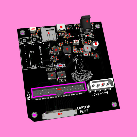

Coming soon - hippity hoppity here comes a floppity 💾 🐇
We had a quest to do some floppy projects back in 2022 (https://blog.adafruit.com/2022/02/09/refactor-of-adafruit_floppy-for-timer-support-mac-disk-success/) but our eyes were bigger than our BOM - many components we designed into this floppy interface board were not available… but now we're back and it's time to make the bestest floppy archiver/writer/emulator(?)
First is the power supply - we need both 5V and 12V. We tried sourcing split 5/12V supplies but were not successful. so instead we can have a 12V power plug and a 5V ~3A buck converter based on the TPS563201 (https://www.digikey.com/en/products/detail/texas-instruments/TPS563201DDCT/5813458). we've also got a TPS259540 12V OVP chip (https://www.digikey.com/en/products/base-product/texas-instruments/296/TPS259540/28780) to make sure the 12V power supply doesn't get swapped with a 15V by accident. USB C can be used when no 12V is needed.
An RP2040 does all the heavy lifting for floppy interfacing. There's a 16M onboard flash plus an optional MicroSD card, so you can save raw disk flux dumps or 1:1 images. We tossed a 1.3" color TFT that might be useful for status updates. Also, we'd like to enable the ability to do off-line archiving - no computer is needed, and a display is essential.
Right now, we only have standard 34-pin IDC and 26-pin 'laptop' floppy pinouts. But we might look at adding disk ][ as well, since we got some Apple disk reading working. Since we have some silksreen room - the PCB is floppy disk sized but tbh we don't need that much space - we added some adorable floppsy bunny art.
#adafruit#floppy#archive#disk#pcb#idc#techproject#electronics#retrotech#hardwarehacking#diyelectronics#rp2040#buckconverter#powersupply#floppydisk#tftdisplay#microsd#offlinearchiving
9 notes
·
View notes
Text
The five main functions of solder mask plug holes
1️⃣ Preventing solder from flowing through the vias and causing short circuits during #PCB wave soldering, especially when vias are placed on #BGA pads. It is necessary to plug the holes before gold plating to facilitate BGA soldering. 2️⃣ Avoiding flux residue inside the vias. 3️⃣ After surface mount assembly and component placement, the PCB needs to undergo vacuum suction on a testing machine to create negative pressure for completion. 4️⃣ Preventing solder paste from flowing into the holes and causing solder voids, which could affect the soldering during assembly. 5️⃣ Preventing solder balls from popping out during wave soldering, which could lead to short circuits.

#pcb#pcb assembly#pcb designer#pcb layout#pcb production#pcb manufacturing#pcb supplier#hdi pcb#flex pcb
4 notes
·
View notes
Text
A controller with a scroll wheel, you say?
Well this is a little funny. Yesterday I posted the first part of a series of post on the fine details of how computers work, mentioning how I've been looking into this as part of a personal project I've been working on, and today I wake up to see Masahiro Sakurai posting a youtube video lamenting the lack of... this exact thing I'm working on.
Apologies for how much cat hair is in this photo, that's a bit of an occupational hazard, but this here is a photo I took back in September when most of the parts I had to order were in for the prototyping of this thing:
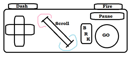
That's a really bad MS Paint mockup, but yeah. I'm designing my own game console, and one of the key features is a big ol' scroll wheel right in the center of the controller. Another is that I'm planning to just put all the designs of the circuit boards and 3D printer files for the casing/buttons up online for free, making it this totally open DIY thing where anyone who's a big enough nerd can just make a couple downloads, order some dirt cheap components, and build their own copy of the system (or people with better setups than me can build and sell them, whatever). So I'm not super worried about anyone stealing my ideas or whatever, but I WOULD like to establish a standard and all that, and figured it was worth noting that this is something I've been slowly working towards for like a year or two now, and didn't just get the idea from this video:
youtube
But yeah, now that the idea's out in the public consciousness, here's the plan for the controller (that I was planning to keep under my hat until I had a working prototype and some demo software sometime next year).
First off, the plan is that this is to be the standard controller for a whole console I'm also plucking away at designing, which is a bit more ambitious of a project, so I figure I might as well make it compatible with something that's already out there. So specifically, I'm designing this so that you can take one, plug it right into an SNES (or with a different connector at the end, an NES, because turns out they use the exact same input handling standard and it's just the shape of the plastic on the end that differs), and have it just work. Or mostly work anyway. I'm hoping I can process a signal out of the scroll wheel in a way that it either just needs the 3 extra bits of the input signal I don't have buttons for in my design (more on that later) or failing that, I can get it to output the same sort of signal as one wheel in the SNES mouse, which just rides along the second data line very few things use. I think that plan might break multitap compatibility and require an extra chip on the controller PCB, but it would leave this slightly more compatible with existing games on the same hardware. I might also do something weird with the button mapping to be sure NES select is on a shoulder and it works right out of the box with that whole library.
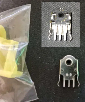
Working out exactly how to handle signals from the scroll wheel happens to be the point I'm currently stuck on by the way. I got this baggie full of rotary encoders for just a few cents which... almost fit in my first draft 3D printed wheel housing, but I have NO documentation on them, not even a part number/manufacturer besides "H-9," the pins don't fit a breadboard, and I've kinda been scrambling for rent so I can't afford a nice multimeter or oscilloscope to poke around with. Plus again I need to redesign this wheel print to even get it to spin right, and... this was a gift from a friend with a printer who is Not Local. Solvable problem, just needs more time and/or outside expertise.
But yeah, once I have those kinks worked out, it should be easy enough to get a custom board design made, replicas of end-cap of the controller cord are another problem easily solved by ordering a 1 dollar part or 3D printing something. The actual cord might be tricky since I don't know where you actually order something like that from, but it should be easy enough for anyone who doesn't mind a little assembly work to put one of these together and have it good to go for any software made with it in mind, or retrogames where you don't mind a weird button count. So... what's the pitch on this scroll wheel anyway?
Well for starters, there's the stuff Sakurai got into this morning. Any sort of RPG or text heavy game can use it to quickly scroll through menu options, or stuff in a text-heavy game. You could also pan the screen with it, something a lot of early 16-bit games assigned to the shoulder buttons or holding up and down while getting used to the new options the hardware was giving them.
Past that, you'll notice in my design it's at a 45 degree angle. I might have to tweak it a little, but my thinking is for a game that uses it heavily, one thumb or the other can slide over easily enough (I'm going for a pretty compact overall design) so we can have some games where you take your thumb off the D-pad, and have this nice analogue steering wheel. Nice for fine control in a racing game, or if you want some little radio-tuning/safe-cracking sorta deal.
Alternatively, move your right thumb over, use the D-pad to steer, shoot and dodge or whatever with shoulder buttons, and use the wheel to rotate a turret for a twin-stick sort of game maybe.
Or just use it for the sort of stuff mouse based games stick on the scrollwheel. Changing weapons, changing powerups... I'm planning to officially label the directions "hot" and "cold" to encourage weird gimmicky things like... I dunno, a platformer where you have a thermostat in your controller you can always mess with, freeze water coming out of pipes, crank up flame jets? Have a shot charging mechanic where you just really crank it to get to max strength? Weird minigame stuff. There's some fun space to explore with it.
Then we have the rest of the design here... which basically comes down to me being just plain sick of how every controller made by anyone in the past... 20 years give or take has kind of the exact same layout? 4 good face buttons, a D-pad, 4 shoulder buttons, 2 sticks, and 1-4 annoying to reach tiny awkward middle buttons, and we're just kind of overdue for a change-up?
Like first of all, hey, this is just too many buttons. There's a ton of games that really only need a D-pad, and maybe 3 buttons (attack jump pause) and the two things that aren't fully standardized is how awkwardly placed the D-pad is and how awful and awkwardly placed the pause button is. Shoulder buttons can be nice, but I've never really felt like 4 of them awkwardly crammed on the rim has been really useful or ergonomic, and that's coming from someone who's been playing a ton of FF14, which gets more use out of them than anything else I could name. And really, aside from games doing fake twin-stick stuff and using the whole grid like a second D-pad, I'm having a really hard time thinking of any game I've ever played that really makes good use of 4 good face buttons? Like people will use them if they've got'em sure, but unless you do that keyboard style thing where you lay the controller on a table and use all your fingers, you can really only comfortably hit 2 face buttons without sliding your thumb away from them, maybe comfortably make a quick pivot to a third.
Also, really, a lot of designers just sort of feel compelled to map SOMETHING to every button, even if it's clear the design didn't really need them. So basically I figure I'll try kinda just taking a "less is more" approach here. Here's the buttons that it's comfortable to rest your thumbs and fingers on, here's a dedicated pause/menu button where people often stick a kind of redundant menu button, here's my gimmicky scrollwheel. That's it, work around that.
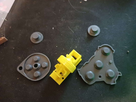
I'm also going a little Gamecube inspired (literally using replacement membranes for one in my prototype design, even). Gonna make a great big primary button and use different shapes for the other two. Trying to label these in a less arbitrary fashion than most. If shooting a gun is a thing you do in this game, and there isn't a real good reason not to, default it to this nice right trigger you can hold down all the time. If we're advancing through menus or jumping or holding down gas in a car, here's the big GO button. Need brakes, need to break stuff with a melee attack? Go back in a menu system? There's your other face button. Have a quick dash move or a run you hold down, let's just use the other shoulder.
So yeah. That's my controller. Need to work out the kinks on the scroll wheel, source a cord, and hopefully I can slap things together and this will be something you can just order bits for piecemeal and put together for like, $5-10 after shipping? Maybe less? The parts are shockingly cheap so far.
But yeah if anyone has any insight to the scroll wheel or cord issues, let me know. Also the whole thing is presently a tad back-burnered because I am in a serious financial crisis and I don't want to have electronics spread all over my table if I have to abruptly find a new place to live if I can't scrape next month's rent together. So as usual, donations are incredibly welcome.
2 notes
·
View notes
Text
Moisture sensor development - 2022/23
Multiple sensors have been running over winter 22 to summer 23 and some problems have arisen:
One temperature sensor stopped functioning but in a way that eluded the error detection. The symptom was that the two sensors showed exactly the same measurement. This turned out to be a configuration issue, where both sensor were mapped to the same temperature.
Battery life was too short on a couple of sensors. This may be because of poor quality batteries, poor connections in the battery holder or due to excess drain somewhere. After experimentation with better quality batteries (Samsung 25R rated at 2500 mAh) it seems the main problem is poor quality batteries.
Moisture sensors losing discrimination. On a new sensor the range from wet to dry is typically 900 but this reduced to 270. I found that cleaning off the old silicon sealant, cleaning the board and resealing brought the readings back to normal.
Moisture sensor connection. The waterproofing with silicon and the JST connector are a poor design. Securing this connector with a zip tie helps to secure this connector.
Rusty main board. One device failed due to rust getting into the pins and socket on the main board connector. This is evidence of moisture in the device container. The sensor cable entrance is sealed with a large amount of silicon sealant which often fails. However when a second device also failed, having drained new , quality batteries very quickly, it seems that the idea of using socket strips on an outdoor device, however well sealed, is a mistake. In any case the board and the chip are really the only significant components so they may as well be soldered together.
One sensor on a public Tiny Forest was stolen. This despite being well - hidden and having a notice inside the box explaining the scientific purpose of the device.
I had considered changing the design of the PCB to avoid the use of a ground plane since I found this made soldering to ground terminals difficult and poor connections created problems. On reflection, my problem is probably insufficient thermal inertia in my small iron and the use of a better, temperature-controlled iron would solve this issue whilst retaining the benefits of a ground plane.
Labels printed on a label printer fade very quickly in sunlight.
An error in the code for the test phase meant that sleep time could be negative with odd results.
It has been suggested that over-the-wire updating of the code should be implemented but I am concerned about the current demand,
Improvements
Have a working set of all three sensors which can be plugged into a device to check the cause of a failed sensor.
Replace the cheap 18650 batteries with Samsung 25R flat top batteries.
Solder the chip directly to the PCB instead of using a socket strip
Develop a better sealing system for the cable entry.
Use a chinagraph pen for labeling
Reconsider strategy for protecting devices in public places
3 notes
·
View notes
Text
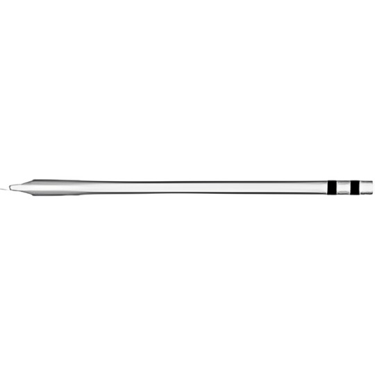
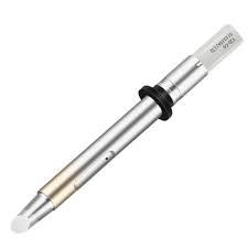
Soldering Tip: What Makes It Essential for Precision Electronics?
Understanding the Purpose of a Soldering Tip
The core of every successful soldering job
When working with delicate electronics or industrial components, the soldering tip plays a vital role in achieving clean, durable connections. It is the heated end of a soldering iron that directly contacts the material, making it an indispensable part of any repair or assembly process involving circuits, connectors, switches, and thermal pads.
Whether you're working on microcontrollers, capacitors, or tools like fuses and contactors, choosing the right soldering tip determines the accuracy and quality of your work. These tips vary in shape and size, each serving a specific purpose depending on the task at hand—from joining tiny cables on microprocessors to assembling LED strips and laptop circuits.
Types of Soldering Tips and Their Uses
Matching tips with the right components
Different electronics demand different tip types to ensure seamless conductivity and minimal heat damage. Below are some common types of soldering tips and their typical applications:
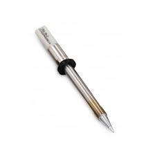
Conical tips are ideal for precise point soldering on small components like sensors or LEDs.
Chisel tips are perfect for general-purpose tasks, including wires, thermal fuses, and circuit board pads.
Bevel tips help with drag soldering, making them suitable for multi-pin connectors and microcontroller boards.
Knife tips are used for rework jobs, especially when dealing with SMT components or pads.
Each shape caters to various components—whether it’s switches, cables, grips, or thermal oils—so understanding which tip matches your job enhances both speed and precision.
Choosing the Right Material for Your Tip
Why tip composition matters
A soldering tip's material affects how well it holds heat, resists corrosion, and maintains durability. Most high-performance tips consist of a copper core for excellent thermal conductivity, coated with layers of iron, nickel, and chrome for enhanced lifespan.
Copper delivers superior heat transfer to electronics and microprocessors.
Iron plating increases durability, making it suitable for repetitive soldering on capacitors or fuses.
Nickel and chrome prevent oxidation when working with oils or adhesives.
Specialized coatings allow better performance when working with lead-free solder used in safety-compliant devices and tools.
Selecting a quality tip material ensures that your soldering process is both efficient and reliable across applications, from laptop circuit boards to industrial controllers.
Key Features to Look for in a Soldering Tip
Factors that make a difference in your workflow
Before purchasing a soldering tip, consider the following performance indicators:
Thermal recovery time, which determines how quickly the tip regains optimal temperature.
Compatibility with your soldering station or thermal controller system.
Shape and size based on whether you're working on fine-pitch electronics or robust cables and contactors.
Durability for prolonged usage on high-wear jobs like connector plug installation or PCB repairs.
These features are crucial for reducing downtime and ensuring safety when operating on sensitive items like sensors, LEDs, or thermal pads.
Best Practices for Soldering Tip Maintenance
Keep your tip in peak condition
Even the best soldering tips require proper care to maintain performance and avoid premature failure. Following a consistent maintenance routine can drastically extend tip life and improve results:
Always tin the tip before and after use to prevent oxidation.
Clean using brass wool instead of wet sponges to retain heat efficiently.
Avoid excessive pressure when soldering, especially on components like capacitors or switches.
Use tip conditioners or thermal oils when you notice signs of oxidation.
Replace damaged tips immediately to prevent inconsistent soldering on microcircuits or controllers.
Proper maintenance leads to clean joints, consistent heat transfer, and long-lasting tools—vital when soldering anything from laptop boards to LED lights.
Applications of Soldering Tips Across Industries
Versatile use beyond just electronics
Soldering tips aren’t limited to circuit boards—they’re used in numerous sectors that depend on thermal accuracy and electrical connectivity:
In the automotive industry, tips are used to solder connectors, fuses, and sensors within vehicle control systems.
In telecommunications, they help assemble intricate wiring, cables, and contactors found in routers and modems.
In consumer electronics, tips ensure robust joints in devices like microcontrollers, laptops, and thermal modules.
In industrial automation, tips are vital for controller repairs and microprocessor-based systems.
Their widespread use showcases the flexibility and importance of having the right soldering tip for every project.
How to Improve Your Soldering Results
Tips to master tip performance
Achieving professional-level soldering requires more than just the right tools—it’s about technique and awareness:
Use the correct tip temperature when working on sensitive components like sensors or thermal pads.
Preheat larger surfaces such as connectors and cables to ensure better solder flow.
Practice on discarded boards to perfect your technique before handling valuable microprocessors or switches.
Avoid frequent tip replacements by investing in high-quality thermal pads and tip care accessories.
By honing your skills and using the right gear, you can significantly enhance the reliability of solder joints across all types of components, from basic fuses to advanced controllers.
Conclusion: The Unsung Hero of Electronics Assembly
Why the soldering tip is more than just a tool
While it may seem like a small part of your toolbox, the soldering tip is critical to achieving precision and performance in electronics, automotive systems, and hardware integration. From thermal conductivity to shape design, every feature impacts your end results—whether soldering capacitors, securing cables, or maintaining safety standards in devices.
0 notes
Text
⚡ Ever wondered how an electric rickshaw controller is manufactured from scratch?
In this video, we take you inside a real factory in China to show the full production process of an **electric rickshaw motor controller**—from PCB assembly to functional testing and final packaging.
--- ### 🛠️ What’s Inside a Rickshaw Controller?
An electric rickshaw controller is the brain of the vehicle. It manages power delivery to the motor, controls speed, braking, and safety systems. Precision and durability are critical.
--- ### 🧩 Manufacturing Process Includes:
1. **SMT (Surface Mount Technology)** – High-speed placement of ICs, MOSFETs, and resistors on the PCB
2. **Through-Hole Component Insertion** – Manual or semi-automated plug-in for capacitors, connectors, and coils
3. **Wave Soldering** – For firm electrical connection on double-layer boards
4. **Housing & Assembly** – Controller casing, thermal pads, and wiring
5. **Software Programming** – Flashing firmware via TTL/USB interface
6. **Functional Testing** – Load simulation, voltage checks, heat profile
7. **Labeling & Packaging** – Ready for shipment to OEM customers
--- ### 📦 Applications:
- Electric rickshaws (e-rickshaws)
Low-voltage electric vehicles
- Cargo trikes
- EV conversion kits
--- 🎥 Shot in one of our OEM partner factories specializing in motor control systems for emerging markets across Asia and Africa.
📩 **For sourcing inquiries, custom controller designs, or OEM orders:** [email protected]
📌 Don’t forget to subscribe, like, share, and if you want more behind-the-scenes looks at real electronics manufacturing in China.
Shanghai Glary
www.glarysh.com
WhatsApp: +86 134 8226 3375
#rickshaw#electronicsmanufacturing#PCBA#motorcontroller#EVcontroller#elainesourcing#SMT#ChinaFactory#controller#electric#electric vehicles#motor#ev#electric rickshaw
0 notes
Text
R+ Max 2D Data Matrix Reader
In industries where traceability, speed, and precision are critical, the ability to read 2D barcodes quickly and accurately can make or break a production line. That’s where the R+ Max 2D Data Matrix Reader shines. Built for rugged industrial environments, this powerful barcode reader offers unmatched performance in decoding 2D Data Matrix, QR codes, and barcodes across a wide range of materials and surfaces.
Whether you're in pharmaceuticals, electronics, automotive, or packaging, the R+ Max is your go-to solution for automated identification and data capture (AIDC).
🔍 What is the R+ Max 2D Data Matrix Reader?
The R+ Max is a high-performance 2D barcode scanner designed to read Data Matrix codes, QR codes, and linear barcodes even on reflective, curved, or rough surfaces. It uses advanced image processing and decoding algorithms to deliver fast, reliable, and precise code reading — even at high conveyor speeds.
💡 Key Features of the R+ Max 2D Reader
⚙️ 1. High-Speed Scanning
Reads codes in milliseconds, keeping pace with fast-moving production lines.
🎯 2. Advanced Decoding Technology
Capable of reading damaged, low-contrast, or distorted codes, even on challenging surfaces like metals, plastics, and glass.
🔁 3. Flexible Integration
Compatible with multiple communication interfaces including Ethernet, RS-232, and USB, making it easy to integrate into existing systems.
🔍 4. Wide Field of View
Supports a variety of working distances and angles — perfect for both inline and robotic scanning applications.
🌐 5. Compact & Durable Design
Built to endure industrial environments with IP-rated enclosures and resistance to dust and vibration.
🏭 Industrial Applications
🏥 Pharmaceuticals
Track & trace for blister packs, vials, and cartons.
Serialization compliance (DSCSA, EU FMD)
🚗 Automotive
Part identification, VIN tracking, and production traceability.
Reading laser-etched or dot-peened codes on metal parts.
💻 Electronics
PCB component tracking, microchip ID scanning.
📦 Packaging & Logistics
High-speed carton tracking, inventory management, and error-proofing.
🛠️ Medical Devices
UDI (Unique Device Identification) verification and compliance.
📊 Technical Specifications
FeatureSpecificationCode Types SupportedData Matrix, QR Code, Aztec, PDF417, 1D barcodesReading SpeedUp to 60 frames per secondCommunication PortsEthernet, RS-232, USBOperating Temperature0°C to 50°CProtection RatingIP65 / IP67 (varies by model)ResolutionUp to 5MP sensor optionsSoftwareUser-friendly interface for setup & diagnostics
🔑 Why Choose the R+ Max 2D Data Matrix Reader?
✅ Reliable in Harsh Conditions
✅ Reads Poor Quality & DPM Codes
✅ Easy Integration with PLCs and ERP Systems
✅ Minimizes Production Downtime
✅ Future-Proof & Scalable
The R+ Max Reader is trusted by factories and warehouses around the world for its consistent read rates, plug-and-play setup, and real-time error detection. It's the smart investment for businesses looking to digitize and automate their traceability processes.
🔎 SEO Keywords to Target
R+ Max 2D Data Matrix Reader
Best industrial barcode reader
2D barcode scanner for manufacturing
Data Matrix code reader for metal parts
QR code scanner for automation
High-speed barcode reader
DPM code reader
Industrial camera scanner for traceability
🚀 Conclusion
The R+ Max 2D Data Matrix Reader is more than just a scanner — it's a critical component in smart manufacturing and Industry 4.0 systems. Designed for accuracy, durability, and speed, it ensures seamless data capture from product to packaging.
Looking to improve traceability and reduce manual errors? Choose the R+ Max — the reader that works as hard as your production line does.
📞 Contact us today for a demo, pricing, or integration support. Let R+ Max supercharge your factory floor!
0 notes
Text
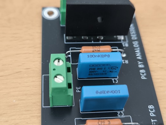
Premium Ground Lift for SSLV1.3 UltraBiB – Black 100x50mm Dual Mono Design
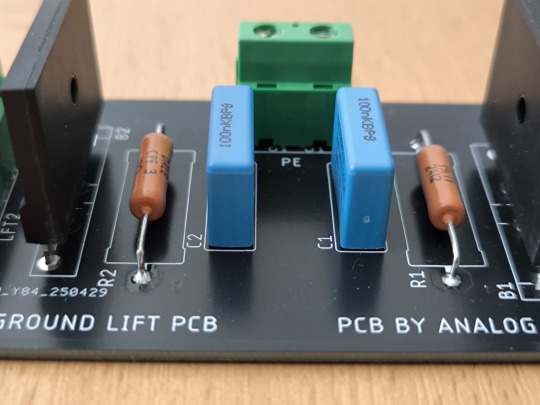
If you're building a high-performance audio power supply and looking to eliminate ground loop noise effectively, the Ground Lift is an essential upgrade. This high-quality printed circuit board is specifically designed to improve audio signal purity by breaking ground loops and ensuring proper grounding in dual mono power supply configurations.
Optimized for Ground Loop Suppression
Ground loops are a common issue in hi-fi and studio-grade audio setups, often introducing hum and interference that degrade sound quality. Our ground lift PCB implements a reliable method to isolate grounds between interconnected audio devices, significantly reducing unwanted noise.
This design is optimized for use with the SSLV1.3 UltraBiB power supply, a popular choice among audio DIYers for its excellent voltage regulation and sonic transparency.
Key Features:
Premium Component Selection
Vishay Dale CPF series 3W metal film resistors ensure long-term thermal and electrical stability.
A robust GBJ3510 bridge rectifier (35A) offers high surge capability and efficient current handling.
KEMET PHE series polypropylene safety capacitor (100nF) provides superior EMI suppression and reliability.
TE Connectivity connectors guarantee secure, long-lasting electrical connections with minimal resistance.
Ground Lift Functionality Efficiently isolates signal and power ground paths to prevent hum and interference from ground loops.
Dual Mono Compatible Designed for dual mono PSU architectures, ensuring clean power delivery to each audio channel.
Compact & Stylish Form Factor
Dimensions: 100mm x 50mm
Black PCB finish for sleek aesthetics and added durability.
High Current Capability Engineered to handle the demands of modern hi-fi components, this board supports high current applications thanks to heavy copper traces and premium layout design.
Why Choose This Ground Lift PCB?
When building high-end audio equipment, every detail counts. By integrating this ground lift module with your SSLV1.3 UltraBiB regulators, you're ensuring a clean power foundation that directly translates to better sound—free from buzz, hum, or interference.
With top-tier components, rugged design, and thoughtful layout, this PCB offers audiophile-grade performance with true plug-and-play convenience for DIYers and professionals alike.
0 notes
Text
Hindware Chimney Repair: Quick & Reliable Fixes for a Smoke-Free Kitchen
In every modern Indian kitchen, a chimney is no longer a luxury—it’s a necessity. Among the leading brands, Hindware chimneys have made a name for themselves with stylish designs and powerful performance. But just like any other appliance, even the best chimneys need attention, repairs, and maintenance over time.
If your kitchen is filling up with smoke or your chimney is making strange noises, don’t worry—you’re not alone. Thousands of households face similar issues, and the good news is that they can be fixed quickly and efficiently with the right service.
Welcome to the ultimate guide on Hindware Chimney Repair—where we walk you through common problems, repair solutions, expert service options, and how Chimfixer can help you get your kitchen back to fresh and functional in no time.

Common Problems in Hindware Chimneys
Even the most reliable appliances run into trouble occasionally. Understanding the most frequent issues can help you detect a problem early and avoid bigger repair costs.
1. Motor Malfunction or Noise
The motor is the heart of your chimney. If it’s not running smoothly or making grinding sounds, it might need cleaning, lubrication, or replacement.
2. Reduced Suction Power
Is your chimney failing to pull out the smoke and odor? Oil-clogged filters or a damaged motor could be the culprit.
3. Grease and Oil Build-Up
Without proper cleaning, oil and grease can clog the filters, leading to poor performance and potential fire hazards.
4. Auto-Clean Function Not Working
The auto-clean feature is one of Hindware’s most convenient options, but it can fail due to PCB issues or faulty sensors.
5. Touch Panel or Remote Malfunctions
Unresponsive controls or broken panels often indicate electronic failure and need professional attention.
6. Power Supply Problems
If the chimney doesn’t turn on, check the power plug—but if the problem persists, internal wiring or fuse issues might be to blame.
7. Foul Smells or Smoke Leakage
Unusual smells or visible smoke in the kitchen even after the chimney is turned on? It could be poor ducting, blocked filters, or suction issues.
Signs You Need Hindware Chimney Repair
Often, homeowners ignore the early signs of chimney trouble until it turns into a major repair job. Here are some warning signs that should never be overlooked:
Strange or loud noises during operation
Weak suction even after cleaning
Persistent odor after cooking
Buttons or sensors not responding
Oil dripping from chimney hood
Frequent short circuits or power trips
Recognizing these signs early can save you time, money, and ensure your kitchen remains smoke-free and safe.
Quick & Reliable Repair Solutions by Experts
When your Hindware chimney starts acting up, don’t panic. Professional technicians like those at Chimfixer offer fast and reliable solutions tailored for Hindware chimney repair. Here's what a typical service visit might include:
✅ On-Site Diagnosis
A trained technician performs a full system checkup to identify the root cause—whether it's motor damage, filter blockage, or PCB failure.
✅ Genuine Spare Parts Replacement
Using original Hindware spare parts ensures performance and durability. From motors to filters, Chimfixer only installs branded components.
✅ Motor & Fan Blade Repair
If your chimney motor is jammed or noisy, experts clean or replace the motor and fan blades, restoring the chimney’s suction power.
✅ Touch Panel & PCB Servicing
Chimfixer technicians repair or replace the touch control panel and circuit board when there are display issues or unresponsive buttons.
✅ Filter Cleaning & Replacement
Old, greasy filters are either cleaned with industrial solutions or replaced if they’re beyond repair.
✅ Full System Rewiring (If Needed)
For chimneys with burnt wiring or frequent short circuits, our technicians provide safe and professional rewiring to restore function.

Why Choose Professional Hindware Chimney Repair Services?
You might be tempted to try a DIY fix, but a kitchen chimney involves electrical, mechanical, and electronic components. Here’s why opting for professional Hindware chimney repair is the smarter choice:
Brand-Specific Expertise
Chimfixer technicians are trained specifically in Hindware models, ensuring accurate troubleshooting and lasting solutions.
Time-Saving & Hassle-Free
Forget waiting weeks for help. We offer same-day chimney repair in many areas, minimizing your kitchen downtime.
Genuine Parts with Warranty
Repairs done with authentic Hindware parts ensure performance and come with service warranties for peace of mind.
Transparent Pricing
No hidden costs. You get upfront quotes and affordable packages customized to your chimney’s condition.
Friendly & Verified Technicians
All service personnel are background-verified, polite, and punctual. Your home and your chimney are in safe hands.
Basic DIY Troubleshooting Tips (Only If You Know What You're Doing)
If you’re comfortable handling small home appliances, there are a few simple checks you can do before calling a technician:
Check the power plug and voltage
Clean the outer filter and mesh using warm soapy water
Reset the touch panel (refer to your model manual)
Make sure the chimney flap isn’t blocked by debris
Important: Avoid opening the internal motor or circuit board yourself. DIY fixes without proper training can damage the unit and void the warranty.
Chimfixer – Your Trusted Partner for Hindware Chimney Repair
At Chimfixer, we specialize in fast, affordable, and expert Hindware chimney repair services. Whether it's a minor issue or a major breakdown, we ensure:
Doorstep service within 24 hours
Genuine spare parts for Hindware chimneys
Trained technicians with years of experience
Easy online booking via website or WhatsApp
We serve all major areas including Kolkata, Howrah, Salt Lake, New Town, Dum Dum, and beyond.
With a high customer satisfaction rate, Chimfixer has become the go-to choice for reliable chimney servicing across Eastern India.
Preventive Maintenance Tips for Hindware Chimneys
Want to avoid frequent repairs? Here’s how you can keep your Hindware chimney in top shape year-round:
Monthly Filter Cleaning
Wipe down mesh filters with warm water and dish soap. For baffle filters, soak and scrub gently every 3–4 weeks.
Auto-Clean Activation
If your model has an auto-clean feature, run it once every 15–20 days to prevent oil buildup.
Unplug When Not in Use
Helps avoid short circuits and conserves energy.
Schedule Annual Professional Service
A deep clean and inspection once a year keeps all components in peak condition.
Conclusion: Don’t Wait—Fix Your Hindware Chimney Today!
Your kitchen chimney does the hard work of keeping your cooking space clean and smoke-free. Don’t ignore the warning signs. Whether it’s noise, weak suction, or sensor failure, Hindware chimney repair is best left to professionals who know the system inside and out.
With Chimfixer, you’re not just getting a technician—you’re getting a partner in your kitchen’s cleanliness and safety. Our quick, reliable, and affordable service ensures your Hindware chimney performs like new again.
Ready to Book a Service?
📞 Call us or WhatsApp now 🌐 Visit chimfixer.com 📍 Service Available in Kolkata, Howrah & Nearby Areas
✅ Hindware Chimney Repair Experts You Can Trust. 💨 Quick Fixes. Long-Lasting Results.
0 notes
Text

Printed Circuit Board Assembly
Printed circuit board assembly service (PCB files and BOM list, please send to) [email protected] (Quick quotation)
Printed circuit board assembly is a process that requires not only knowledge of printed circuit board components and assembly, but also understanding of printed circuit board design, printed circuit board manufacturing, and a deep understanding of the final product. Circuit board assembly is just one of the challenges in delivering a perfect product for the first time.
Printed circuit boards (PCBs) are widely used in many industrial and consumer electronics products. The multifunctionality of PCB comes from its lightweight, compact, and flexible structure, which can adapt to any complex circuit. Although PCBs are relatively common, their complexity makes it crucial to procure new circuit boards from reliable suppliers. Printed circuit board assembly services take advantage of these complexities.
Hitech Group provides comprehensive printed circuit board assembly services to help our customers fully realize their designs. We have extensive experience in collaborating with clients in highly innovative industries such as communication, automotive, industrial control, medical equipment, oil and gas, and security.
We offer the following PCB assembly services:
Quick-turn prototype assembly
Next day rush and standard 5 day turns
Turn-key
Partial turn-key
Consignment
RoHS compliant lead-free assembly
Non-RoHS assembly
Conformal coating
Testing Services - Functional and electrical testing
Panel assembly
Complete product box builds
PCBA manufacturing process Electronic component procurement PCB manufacturing SMT patch DIP plug-in circuit board assembly testing finished product assembly PCB assembly requires electronic components and consumables Printed circuit board, electronic components, welding wire, solder paste, welding rod, solder preform (depending on the type of soldering), oxide powder, soldering platform, wave soldering machine, SMT equipment, testing equipment PCB manufacturing Hitech Group provides complete PCBA manufacturing and partial PCB assembly manufacturing. In the comprehensive PCB assembly manufacturing, we handle PCB production, material procurement, online order tracking, incoming material certification/quality inspection, and final assembly. In some PCB manufacturing, you can order PCBs and some materials yourself, and we complete other parts.
How to obtain one-stop consultation for PCBA manufacturing? BOM quotation, please send your BOM to Hitech Group and inform us of the quantity of PCBs to be manufactured. We will provide you with a PCBA quotation within 24 hours. The bill of materials must include quantity, tag number, manufacturer name, and manufacturer model. Before delivering the PCB components, we will conduct various tests on them. Visual inspection: General quality inspection
X-ray inspection: Check for short circuit cold soldering or bubble issues in BGA, QFN, and other soldering.
Automatic optical inspection: Check for virtual soldering, short circuits, missing parts, polarity reversal, etc.
Online testing Functional testing (based on the testing steps you provided)
What is the definition of PCBA? PCB refers to a blank board, while PCBA is a complete PCB component that contains all the electronic components required to make the board operate as required. PCBA can also refer to the process of assembling a circuit board with necessary components. PCBA companies can use two main methods for PCB assembly:
Surface mount technology Surface Mount Technology (SMT) is an assembly process that involves mounting electronic components onto the surface of a PCB. It has high automation and flexibility, and allows for higher connection density. It enables manufacturers to incorporate complex circuits into small components. The four basic steps of PCBA SMT are: Prepare PCB: First, the assembly personnel place the solder paste on the board where it is needed. Placement of components: Next, assembly personnel typically use picking and placing machines to place the components on the board. Reflow soldering: Assembly personnel then heat the circuit board in a reflow oven until the solder paste reaches the temperature required to form solder joints. Inspection: Assembly personnel conduct inspections throughout the SMT process, including before connecting components and before and after reflow soldering.
Through-Hole technology Through-hole technology is an assembly process that involves drilling holes in a PCB through which electronic components called leads can be connected. It is a technology that is older than SMT, but establishes stronger connections between circuit boards and components, making assembly more durable and reliable. The through-hole assembly can be fully automatic or semi-automatic. The steps of PCBA through-hole process include: Drilling: The first step in the through-hole process is to drill holes on the circuit board. The size of these holes must be suitable for the component leads. Place the lead: Next, the assembly worker places the lead in the hole. Welding: The next step in this process is welding. This step ensures that the components are firmly fixed in place. Inspection: Throughout the process, inspect the components to ensure that the PCBA operates as expected.
Our PCBA Services
At Hitech Circuits, we provide expert PCB assembly services, including board-level and completed box build assembly, SMT and thru-hole technology, and everything from fully automated processes to precise hand assembly.
When you work with Hitech Circuits, you get years of experience on your side, timely service and product excellence. To learn more about how our PCB assembly services can help you meet your goals, contact us online, call us at 18033052358 or request a free, no-obligation quote today.
#pcb assembly#pcb fabrication#pcba#electronics assembly#smt & pcba manufacturer#oem assembly manufacturing#pcb manufacturer#pcb
0 notes
Text
What Are the Advantages of SMT Processing Technology Compared to DIP?
In today's mass-produced electronic hardware, a significant portion utilizes Surface Mount Technology (SMT) processing, which has become an industry trend.
Surface Mount Technology for High-Speed PCBA Processing
From a developmental perspective, the widely adopted SMT soldering process today is essentially a derivative and upgraded version of the DIP (Through-Hole Technology) plug-in process. When using SMT, only the quality of PCB pads needs to be considered, eliminating the need for drilling. This not only significantly improves production speed but also greatly simplifies the process. Although SMT may not offer the same seismic stability as through-hole mounting in certain special environments, its advantages still make it suitable for large-scale application.
Five Key Stages of the SMT Process
PCB Production: This stage focuses on manufacturing the PCB, with emphasis on the quality of solder pads.
Solder Paste Printing: Applying solder paste onto the pads to prepare for the next mounting step.
Component Placement: A pick-and-place machine precisely positions components on the solder paste-printed pads through programming.
Reflow Soldering: Bonding components firmly to the pads via reflow soldering.
PCBA Finishing/Testing/Shipping: Assembling, testing, and delivering the finished PCBA.
Differences Between SMT and DIP Through-Hole Technology
Space Optimization: Through-hole mounting often suffers from space constraints, which SMT addresses effectively. SMT components are smaller and more flexibly arranged, allowing a higher component density per unit area. This enables more powerful functionality in smaller spaces, whereas through-hole mounting has the opposite effect.
Faster Circuit Speed: Reduced component size contributes to higher circuit operation speeds.
Superior Vibration Resistance: SMT has proven more stable in high-vibration or shaking environments.
Cost Efficiency: SMT components typically cost less than their through-hole counterparts.
Shorter Production Cycle: The elimination of drilling significantly shortens SMT production time, accelerating manufacturing and reducing time-to-market. This makes SMT an ideal choice for new product development. Using Design for Manufacturability (DFM) software tools further minimizes rework and redesign needs for complex circuits, enhancing the speed and feasibility of intricate designs. [View the guide on why process control measurements are crucial for preventing defects in SMT PCB assembly.](Link to relevant resource)
If you’re interested in PCB&PCBA products, pls kindly email to Sandy: [email protected]
1 note
·
View note