#Rubycon capacitors
Explore tagged Tumblr posts
Visit Tumblr Blog
Explore Tumblr blogs with no restrictions, modern design and the best experience.
Last Seen Tumblr Blogs


Fun Fact
Tumblr Inc. is funded by 13 investors.
Text
https://www.futureelectronics.com/p/passives--capacitors--aluminum-electrolytic-capacitors/eee-fk1j101p-panasonic-3028632
Low frequency signals, multi section, Nichicon aluminum electrolytic capacitor
EEE-FK Series 63 V 100 uF Ø 10 x 10.2 mm 105 °C Low ESR SMT Electrolytic
#Capacitors#Aluminum Electrolytic Capacitors#EEE-FK1J101P#Panasonic#Low frequency signals#multi section#Nichicon#Rubycon audio#Axial#Audio capacitor#Rubycon capacitors#Low ESR SMT Electrolytic#computer grade#Reforming
1 note
·
View note
Text
https://www.futureelectronics.com/p/passives--capacitors--aluminum-electrolytic-capacitors/eee-1va470wp-panasonic-2028610
Audio capacitor, Axial electrolytic capacitor, Low frequency signal
EEE-S Series 35 V 47 uF Ø 6.3 x 5.4 mm 85 °C SMT V-Chip Aluminum Electrolytic
#Panasonic#EEE-1VA470WP#Capacitors#Aluminum Electrolytic Capacitors#Multi section#Nichicon aluminum#Rubycon capacitors#Audio capacitor#Axial#Low frequency signal#computer grade#low esr#Aluminum oxide#SMT V-Chip
1 note
·
View note
Text
https://www.futureelectronics.com/p/passives--capacitors--aluminum-electrolytic-capacitors/eee-fk1h151p-panasonic-3028618
Axial electrolytic capacitor, Rubycon capacitors, low frequency signal, low esr
EEE-FK Series 50 V 150 uF Ø 10 x 10.2 mm 105 °C Low ESR SMT Electrolytic
#Capacitors#Aluminum Electrolytic Capacitors#EEE-FK1H151P#Panasonic#Axial electrolytic capacitor#Rubycon capacitors#low frequency signal#low esr#Audio capacitor#Miniature multi section capacitor#Low ESR SMT Electrolytic#computer grade#aluminum oxide
1 note
·
View note
Text
https://www.futureelectronics.com/p/passives--capacitors--aluminum-electrolytic-capacitors/eee-fk1j471am-panasonic-9068903
Aluminum oxide, electrolytic capacitors, Audio capacitors, Rubycon capacitors
mm 105°C Aluminum Electrolytic Capacitor
#Capacitors#Aluminum Electrolytic Capacitors#EEE-FK1J471AM#Panasonic#aluminum oxide#Audio capacitors#Rubycon#low frequency signals#Reforming#multi section capacitor#Axial#miniature Nichicon aluminum electrolytic capacitor
1 note
·
View note
Text
Capacitors for Medical Electronics Market: Revenue Trends and Pricing Analysis 2025–2032
Global Capacitors for Medical Electronics Market Size, Trends, Business Strategies 2025-2032
Capacitors for Medical Electronics Market size was valued at US$ 892.6 million in 2024 and is projected to reach US$ 1.47 billion by 2032, at a CAGR of 7.6% during the forecast period 2025-2032
Our comprehensive Market report is ready with the latest trends, growth opportunities, and strategic analysis https://semiconductorinsight.com/download-sample-report/?product_id=59015
MARKET INSIGHTS
The Global Capacitors for Medical Electronics Market size was valued at US$ 892.6 million in 2024 and is projected to reach US$ 1.47 billion by 2032, at a CAGR of 7.6% during the forecast period 2025-2032.
Capacitors for medical electronics are specialized passive components that store and regulate electrical energy in medical devices. These components play a critical role in ensuring stable power delivery, noise filtering, and signal conditioning across various medical applications. The primary types include ceramic capacitors (known for high-frequency performance), tantalum capacitors (valued for high volumetric efficiency), and plastic capacitors (preferred for high reliability).
The market growth is driven by increasing adoption of advanced medical imaging systems, rising demand for implantable medical devices, and stringent regulatory requirements for component reliability. The shift toward miniaturized medical electronics is particularly accelerating demand for high-density capacitors. For instance, in Q1 2024, TDK Corporation launched a new series of high-capacitance MLCCs specifically designed for portable medical devices, addressing the need for compact power solutions in wearable health monitors.
List of Key Capacitor Manufacturers for Medical Electronics
Murata Manufacturing Co., Ltd. (Japan)
TDK-EPCOS (Germany)
AVX Corporation (U.S.)
KEMET Electronics (U.S.)
Vishay Intertechnology, Inc. (U.S.)
Rubycon Corporation (Japan)
Knowles Precision Devices (U.S.)
Exxelia Group (France)
Greatbatch, Inc. (U.S.)
Segment Analysis:
By Type
Ceramic Capacitors Lead the Market Due to High Stability and Reliability in Medical Applications
The market is segmented based on type into:
Ceramic Capacitors
Subtypes: Multilayer Ceramic Capacitors (MLCC), Single Layer Ceramic Capacitors (SLCC)
Tantalum Capacitors
Plastic Capacitors
Subtypes: Polypropylene, Polyester, Polyphenylene Sulfide
Others
By Application
Implantable Medical Devices Segment Dominates Owing to Rising Demand for Miniaturized Components
The market is segmented based on application into:
Implantable Defibrillators
Magnetic Resonance Imaging
Computed Tomography Imaging
X-Ray Machines
Others
By End-User
Hospitals Segment Holds Major Share Due to Expanding Healthcare Infrastructure
The market is segmented based on end-user into:
Hospitals
Diagnostic Centers
Research Institutions
Others
Regional Analysis: Global Capacitors for Medical Electronics Market
North America The North American market leads in technological innovation and regulatory compliance, driven by stringent FDA guidelines and high healthcare expenditures. The U.S. accounts for over 40% of the global medical electronics market, creating consistent demand for high-reliability capacitors in devices like implantable defibrillators and MRI systems. Major players like AVX Corporation and KEMET Electronics dominate the supply chain, focusing on miniaturization and extended lifespan for critical applications. Recent investments in telemedicine and wearable medical devices are expanding opportunities for ceramic and tantalum capacitors. However, supply chain disruptions and material shortages pose challenges for manufacturers.
Europe Europe’s market is characterized by advanced healthcare infrastructure and strict EU MDR (Medical Device Regulation) compliance requirements. Germany and France are key markets, with growing demand for capacitors in computed tomography and radiation therapy equipment. The shift toward renewable energy in medical facilities is driving adoption of capacitors with higher energy efficiency. Local manufacturers like TDK-EPCOS and Vishay Intertechnology emphasize eco-friendly materials to meet circular economy mandates. While the market shows steady growth, Brexit-related trade complexities and inflation have temporarily impacted capacitor pricing and availability in some regions.
Asia-Pacific As the fastest-growing regional market, Asia-Pacific benefits from expanding healthcare access and localization of medical device manufacturing. China’s domestic capacitor production now meets approximately 65% of regional demand, with Japan leading in ceramic capacitor innovation. The Indian market shows particular promise due to government initiatives like Make in India, though quality control remains a challenge in price-sensitive segments. Southeast Asian countries are emerging as production hubs, attracting investments from Murata Manufacturing and other global players. Rapid hospital construction across the region continues to drive capacitor demand for diagnostic imaging equipment.
South America Market growth in South America is constrained by economic volatility but shows niche opportunities in refurbished medical equipment and localized assembly. Brazil represents the largest market, with increasing adoption of capacitors in portable ultrasound devices and patient monitoring systems. However, import dependency and currency fluctuations create pricing instability. Recent trade agreements are improving access to advanced components, while local manufacturers focus on cost-competitive plastic film capacitors for non-critical applications. The lack of standardized testing facilities remains a barrier for high-end medical capacitor adoption.
Middle East & Africa This region presents a bifurcated market — Gulf Cooperation Council (GCC) countries demand premium capacitors for state-of-the-art medical facilities, while African markets prioritize affordability. The UAE and Saudi Arabia are investing heavily in digital healthcare infrastructure, creating opportunities for specialized capacitor suppliers. Sub-Saharan Africa relies primarily on imported medical devices, though local capacitor assembly is gaining traction in South Africa and Nigeria. Challenges include inconsistent power quality affecting component longevity and limited technical expertise for maintenance. Long-term growth potential exists as healthcare modernization continues across the region.
MARKET DYNAMICS
he rapid adoption of artificial intelligence in medical diagnostics is generating unprecedented demand for high-frequency, low-loss capacitors capable of supporting advanced signal processing. Modern AI-assisted imaging systems require capacitors with exceptional stability across wide temperature ranges and minimal equivalent series resistance (ESR). This represents a $1.2 billion opportunity for capacitor manufacturers specializing in high-frequency applications. The development of 5G-enabled remote diagnostic tools is further expanding requirements for capacitors that can maintain signal integrity in wireless transmission environments.
Developing nations are making significant investments in their healthcare systems, with countries such as India and China increasing their medical electronics expenditures by 15-20% annually. This growth is creating opportunities for capacitor manufacturers to establish partnerships with regional medical device producers, particularly in segments like portable ultrasound devices and point-of-care testing equipment. The emphasis on cost-effective solutions in these markets is driving innovation in capacitor designs that balance performance with affordability, opening new avenues for market expansion beyond traditional premium segments.
As medical devices continue shrinking, capacitor manufacturers face fundamental physics challenges in maintaining capacitance values and voltage ratings in progressively smaller footprints. The industry is approaching practical limits for dielectric thickness in ceramic capacitors, with current state-of-the-art layers measuring below 1 micrometer. These dimensional constraints create manufacturing yield challenges, with defect rates increasing exponentially as feature sizes decrease. The push toward sub-0201 case sizes for implantable applications has resulted in assembly difficulties and reliability concerns that require innovative solutions in materials science and production techniques.
The medical capacitor sector faces growing challenges in protecting proprietary technologies, particularly in regions with weaker IP enforcement. Leading manufacturers invest 8-12% of revenue in R&D to maintain technological advantages, but the specialized nature of medical components makes reverse engineering particularly problematic. Recent patent disputes involving barium titanate formulations and electrode deposition techniques highlight the competitive intensity in the sector. These legal challenges divert resources from innovation while creating uncertainty in the supply chain as manufacturers navigate complex licensing agreements.
The market is highly fragmented, with a mix of global and regional players competing for market share. To Learn More About the Global Trends Impacting the Future of Top 10 Companies https://semiconductorinsight.com/download-sample-report/?product_id=59015
FREQUENTLY ASKED QUESTIONS:
What is the current market size of Global Capacitors for Medical Electronics Market?
Which key companies operate in Global Capacitors for Medical Electronics Market?
What are the key growth drivers?
Which region dominates the market?
What are the emerging trends?
Related Reports:
https://semiconductorblogs21.blogspot.com/2025/07/bluetooth-audio-ic-market-strategic.htmlhttps://semiconductorblogs21.blogspot.com/2025/07/dual-in-line-memory-module-dimm-market.htmlhttps://semiconductorblogs21.blogspot.com/2025/07/single-in-line-memory-module-simm.htmlhttps://semiconductorblogs21.blogspot.com/2025/07/ddr4-register-clock-driver-market_4.htmlhttps://semiconductorblogs21.blogspot.com/2025/07/ddr4-register-clock-driver-market.htmlhttps://semiconductorblogs21.blogspot.com/2025/07/tft-lcd-billboards-and-signage-market.htmlhttps://semiconductorblogs21.blogspot.com/2025/07/global-advanced-video-coding-avc-market.htmlhttps://semiconductorblogs21.blogspot.com/2025/07/global-rf-synthesizers-market-strategic.htmlhttps://semiconductorblogs21.blogspot.com/2025/07/ignition-safety-device-isd-market.htmlhttps://semiconductorblogs21.blogspot.com/2025/07/global-external-plug-in-adapters-market.htmlhttps://semiconductorblogs21.blogspot.com/2025/07/global-display-power-management-ic.htmlhttps://semiconductorblogs21.blogspot.com/2025/07/global-display-ic-market-opportunities.htmlhttps://semiconductorblogs21.blogspot.com/2025/07/automotive-nox-sensors-market.htmlhttps://semiconductorblogs21.blogspot.com/2025/07/global-mask-packages-market-size-share.htmlhttps://semiconductorblogs21.blogspot.com/2025/07/global-smart-lighting-market-industry.html
CONTACT US: City vista, 203A, Fountain Road, Ashoka Nagar, Kharadi, Pune, Maharashtra 411014 [+91 8087992013] [email protected]
0 notes
Text
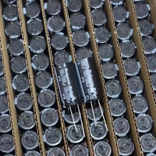
High Quality 1000uf 100v for Rubycon Electrolytic Capacitor Default size:18*36cm.Other specification capacitor are also provided.Talk with us via whatsapp. There is different capacity specification available for the 100V electrolytic capacitor serial: - 100v 1uf - 100v 2.2uf - 100v 4.7uf - 100v 10uf - 100v 33uf - 100v 47uf - 100v 68uf - 100v 100uf - 100v 220uf - 100v 470uf - 100v 1000uf - 100v 2200uf - 100v 3300uf - 100v 4700uf - 100v 6800uf - 100v 15000uf - 100v 22000uf - 100v 33000uf If you have speicified size request,contact us to check. Do you support other specification capacitor? Yes,actually we not only provide differnt specification capacitor but also other electronic components,like IC,Sensor,Microcontroller,Module,Diodes,Transistor,Relay,Connector. If you specified size request,contact us Know more about our company,view here. Read the full article
0 notes
Text
Review, teardown, and testing of LRS-150-24 Mean Well power supply
The LRS-150-24 power supply can operate from a 100–120 volt or 200–240 volt AC network. The manufacturer states it provides an output current of up to 6.5 amperes at 24 volts. The supply measures 5¾ × 3¾ × 1¼ inches (145 × 95 × 30 millimeters), made on a fiberglass printed circuit board fixed to the base's case. The top cover is perforated in a honeycomb pattern. The case and cover are both made of aluminum.
The board is put together neatly, with no visible defects. The components are arranged evenly, and soldering was done with a no-clean flux. Absolutely nothing dangles or rattles in the assembly.
No noises of any sort were noticed during the operation of the power supply.
The power supply uses a flyback circuit without PFC.
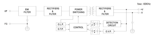
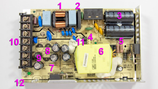
The input voltage is supplied to the input node: RF interference filter (1), a pulse surge limiter (varistor), then the voltage goes to the diode bridge (2) and two input electrolytic capacitors (3). The input voltage selector is also located here. Flyback, built on a MW03A controller (4, installed on the back side of the board) and a power switch (5) on a N-channel MOSFET transistor MMF60R290P. Unfortunately, there is no information about the controller on the Internet. The transistor has a channel resistance of 0.29 ohms at 650 volts and 13 amps. The transformer (6) is entirely covered by the casing, so it is unclear what core material is used. The output rectifier (7) is built using a Schottky diode HBR20150 in a TO-220F package screwed to the side wall and covered with casing. It is basically dual 150V 10A diodes connected in parallel. After the diode there are four output electrolytic capacitors (8) and an additional LC filter. Here (12), there is a small output voltage indicator (green LED) and a regulator (tuning resistor) for adjusting the output voltage. Input and output circuits are connected through a shared screw 7-terminal block (10). 3 terminals for the input line, neutral, and ground wires, and 2 in parallel for common and +24V output.
The main electrolytic capacitors are designed for operating temperatures up to 220°F (105°C), Rubycon. Two optocouplers (11) are installed in the feedback circuit, most likely with phototransistors transmitting control signals from the low-voltage output to the high-voltage input side.
The board has a few cutouts to increase the dielectric strength between the high-voltage and low-voltage sides of the circuit.
The picture shows that the board has three unused spots for storage output capacitors (8), most likely used in the other power supplies of the same series but with different output voltages.
Test conditions
Most tests use metering circuit #1 (see appendices) at 80°F (27°C), 70% relative humidity, and 29.8 inHg pressure.
The measurements were performed without preheating the power supply with a short-term load unless mentioned otherwise.
The following values were used to determine the load level:

Output voltage under a constant load

The high stability of the output voltage should be noted.
Power-on parameters
Powering on at 100% load
The power supply is turned off at least 5 minutes before the test, with a 100% load connected.
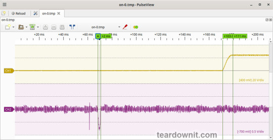
The oscillogram of switching to a 100% load is shown below (channel 1 is the output voltage, and channel 2 is the current consumption from the grid):
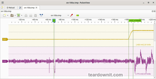
The picture shows three distinguishable phases of the power-on process:
The pulse of the input current charging the input capacitors when connected to the grid has an amplitude of about 7.5 A and a duration of 2 ms.
Waiting for the power supply control circuit to start for about 100 ms.
(Output Voltage Rise Time) Starting the converter, increasing the output voltage, and entering the operating mode) is 8 ms.
(Turn On Delay Time) The entire process of entering the operating mode from the moment of powering on) is 119 ms.
(Output Voltage Overshoot) Output voltage overshoot is absent; the switching process is aperiodic.
Powering on at 0% load
The power supply is turned off at least 5 minutes before the test, with a 100% load connected. Then, the load is disconnected, and the power supply is switched on.
The oscillogram of switching to a 0% load is shown below:
The picture shows three distinguishable phases of the power-on process:
The pulse of the input current charging the input capacitors when connected to the grid has an amplitude of about 7 A and a duration of 2 ms.
Waiting for the power supply control circuit to start for about 103 ms.
(Output Voltage Rise Time) Starting the converter, increasing the output voltage, and entering the operating mode) is 8 ms.
(Turn On Delay Time) The entire process of entering the operating mode from the moment of powering on) is 111 ms.
(Output Voltage Overshoot) Output voltage overshoot is absent; the switching process is aperiodic.
Power-off parameters
The power supply was turned off at 100% load, and the input voltage was nominal at the moment of powering off. The oscillogram of the shutdown process is shown below:

The picture shows two phases of the shutdown process:
(Shut Down Hold Up Time) The supply continues to operate due to the input capacitors holding charge until the voltage across them drops to a certain critical level at which maintaining the output voltage at the nominal level becomes impossible is 31 ms.
(Output Voltage Fall Time) Reduction of the output voltage, stopping voltage conversion, and accelerating the voltage drop is 21 ms.
(Output Voltage Undershoot) Output voltage undershoot is absent, and the shutdown process is aperiodic.
Ripple voltage and current
100% load
The diagram of the current draw from the grid at 100% load is shown in the oscillogram below. The amplitude of the current is about 7.5 A:
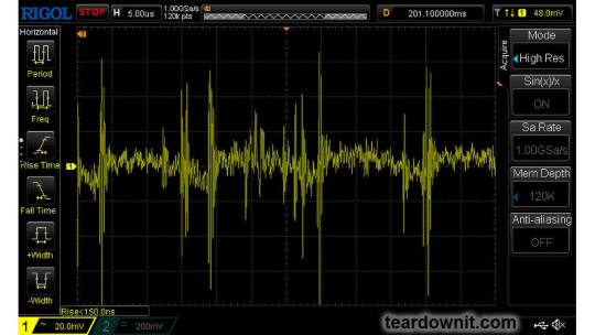
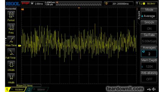
Low-frequency output voltage ripple is under 30 mV (see the oscillogram below):

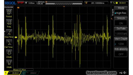
Output voltage ripple at the converter frequency is under 30 mV (see the oscillogram below):

75% load
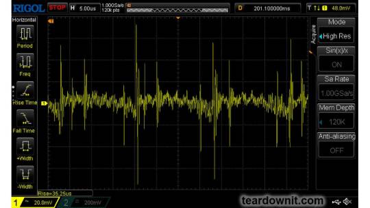
Output voltage ripple at the converter frequency is under 30 mV (see the oscillogram below):
Low-frequency output voltage ripple is under 30 mV (see the oscillogram below):

50% load
Output voltage ripple at the converter frequency stays below 10 mV; see the oscillogram (11):
10% load

0% load
No-load current consumption was measured with a multimeter, which is 60 mA RMS.
(Power Consumption) The first assumption of excessive standby power draw of more than 7 W is wrong since the current in this mode is predominantly reactive. Indeed, the input filter in the circuit contains two capacitors with a capacitance of 0.68 μF each; these low-frequency capacitors are connected in parallel, i.e., an equivalent capacitance of 1.36 μF is connected to the input terminals. A simple calculation shows that the current through these capacitors should be equal to Ic=120×2×pi×60×1.36e-6=61.5 mA. A slight difference from the measured value can be explained by the deviation of the actual parameters from their nominal values and measurement error.
Measuring the exact active power consumption at a 0% load with a basic set of instruments (oscilloscope, multimeter, etc.) is impossible.
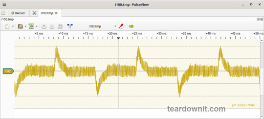
Output voltage ripple at the converter frequency is under 20 mV (see the oscillogram below):

The amplitude of low-frequency output voltage ripples is about 25 mV (see the oscillogram below):

Dynamic characteristics
A mode with periodic switching between 50% and 100% load was used to evaluate the dynamic characteristics. The process oscillogram is shown below (17):

It is evident that the supply’s response to loading changes is close to aperiodic, and there is no overshoot, which indicates a good stability margin. The magnitude of the response to load changes is within 200 mV.
Overload protection
The claimed protection type is "hiccup mode, recovers automatically after fault condition is removed". This was confirmed during testing. When a short circuit occurs, the power supply periodically tries to turn back on and, if the overload is still present, turns off again until the next attempt. This operating mode reduces energy losses and heating during overload. Still, it does not allow the parallel connection of multiple power supplies with a common output.
The output current for the overload protection to kick in is 8.5 A.
Input circuit safety assessment
(Input discharge) Safety assessment is based on the discharge time constant of the input circuits when disconnected from the grid; the value is 0.384 s. This means that when operating on a 120 V input voltage, the time required to discharge the input circuits to safe values (<42 V) will be 0.61 s:

Important: The result is valid for this particular power supply unit; it was obtained for testing purposes and should not be taken as a safety guarantee.
Thermal modes
When operating with no load connected, no component overheating had been noticed.
When operating under load, the input diode bridge heats up most noticeably.
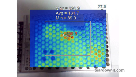
With a load of 90% and the top cover closed, the case heats up to approximately 200°F; the hottest spot is located in the area of the diode bridge rectifier.
With a load of 95% and the lid closed, the case temperature reaches 230°F:
The temperature of the bridge rectifier itself is a dangerous 250°F:
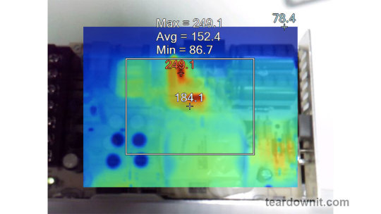
Somewhere around these load values, the power supply goes into a pulse-power-limiting mode and remains in this state either until the load drops or until it cools down. Then this 'heat up', 'limit power', 'cool down', and 'turn back on' cycle repeats.
Other things to consider:
Hot summer weather will decrease the maximum sustainable power output this supply can provide even more.
The tests were conducted with unobstructed air access to the housing for cooling; any changes may increase the heating.
This means that the power supply cannot handle its rated load for a prolonged period with no forced ventilation, and the load should be limited to 5.5 or even 5.0 A.
Conclusions
The reviewed power supply unit has characteristics generally consistent with those declared by the manufacturer, except for the long-term output power, which should be around 120 W.
The build quality is decent; no components clearly unsuitable for the general application, power draw, current, voltage, or temperature were found in the circuit.
The stability of the output voltage should be especially noted.
0 notes
Text
Avtek Mega Data/Fax Modem - Model CD900
This modem was purchased through eBay in February 2023 and recapped in late May 2023 using whatever capacitors I had on hand. Thankfully, I had a bunch of Rubycons and Panasonics. If you order enough of them you always end up with spares. Here’s the brains of the modem. A Rockwell RC224ATF R6641-14 with datecode of week 30, 1992. Some of the surface mount capacitors had leaked but nothing a…

View On WordPress
0 notes
Text
Reforming electrolytic capacitors, Aluminum oxide, rubycon capacitors
ZA Series 35 V 68 uF Ø 6.3 x 7.7 mm Surface Mount Polymer Chip Capacitor
#Capacitors#Aluminum Polymer Capacitors#EEH-ZA1V680XP#Panasonic#Reforming electrolytic capacitors#Aluminum oxide#rubycon capacitors#Surface Mount Polymer Chip Capacitor#low ESL polymer capacitors#polymer capacitors#aluminum organic polymer capacitors
1 note
·
View note
Link
aluminum electrolytic, capacitor, Rubycon, capacitors, axial, radial, audio, multi section, nichicon, manufacturers, reforming, low esr, non polar, cornell dubilier, large, computer, grade, miniature
1 note
·
View note
Text
Aluminum oxide, Aluminum organic polymer capacitors manufacturers
ZA Series 35 V 68 uF Ø 6.3 x 7.7 mm Surface Mount Polymer Chip Capacitor
#Panasonic#EEH-ZA1V680XP#Capacitors#Aluminum Polymer Capacitors#Aluminum oxide#Aluminum organic polymer#Low ESL polymer capacitors#Rubycon solid polymer#Audio capacitor Cornell dubilier#low frequency signal#multi section capacitor
1 note
·
View note
Text
https://www.futureelectronics.com/c/passives/capacitors--aluminum-organic-polymer
A full aluminum organic polymer capacitor selection from several manufacturers including Rubycon that can be used as conductive aluminum organic polymer capacitors or solid polymer capacitors.
#Rubycon solid polymer capacitors#Low ESL polymer capacitors#solid capacitors#Aluminum organic polymer capacitors#conductive polymer capacitors#low ESL#DC-DC converters#Solid polymer capacitor#Automotive Digital Equipment#Aluminum polymer capacitor#Conductive polymer capacitor#Capacitor manufactory
1 note
·
View note

Photo
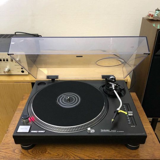
Technics SL-1210MK2, complete dissasambly and overhaul. New capacitors and tranzistors in control board (Nichicon, Rubycon), new custom made RCA Cable, target light LED conversion, proper lubrication and settings (pitch, brake), new slipmat and accessories. #tt #turntable #gramofon #djturntable #dj #technics #technics1210mk2 #japan #ortofon #ortofonconcorde #hifi #45500 #nichicon #rubycon #restoration #audio #sound #musicgear #djgear #33/45 https://www.instagram.com/p/CNvW4z0L6LW/?igshid=1chyoqhnl2byw
#tt#turntable#gramofon#djturntable#dj#technics#technics1210mk2#japan#ortofon#ortofonconcorde#hifi#45500#nichicon#rubycon#restoration#audio#sound#musicgear#djgear#33
5 notes
·
View notes
Link
WT Series 220 uF 50 V 105°C Ø10 x 10 mm SMT Chip Aluminum Electrolytic Cap
1 note
·
View note
Link
A complete selection of aluminum electrolytic capacitors from several different capacitor manufacturers including Rubycon& Nichicon that can be used as multi section electrolytic capacitors, reforming, or radial and axial electrolytic capacitors.
1 note
·
View note