#SoftwareSerial
Explore tagged Tumblr posts
Visit Tumblr Blog
Explore Tumblr blogs with no restrictions, modern design and the best experience.
Last Seen Tumblr Blogs


Fun Fact
US Tumblr user growth rate is estimated to slow down to 4.1%.
Text
Jasne, oto kod dla Arduino, który odczytuje dane z modułu GPS i wyświetla szerokość i długość geograficzną na ekranie LCD:
Potrzebne biblioteki:
* SoftwareSerial.h: Do komunikacji z modułem GPS po serialu (jeśli używasz pinów innych niż sprzętowe TX/RX).
* LiquidCrystal.h: Do obsługi ekranu LCD.
* TinyGPS++.h: Do parsowania danych NMEA z modułu GPS.
Podłączenie:
* Moduł GPS:
* VCC -> 5V Arduino
* GND -> GND Arduino
* TX -> Pin cyfrowy Arduino (np. 2)
* RX -> Pin cyfrowy Arduino (np. 3)
* Ekran LCD:
* Zasilanie i masa zgodnie z instrukcją ekranu LCD
* Piny danych LCD do pinów cyfrowych Arduino (np. 4, 5, 6, 7, 8, 9)
* Pin RS LCD do pinu cyfrowego Arduino (np. 10)
* Pin E LCD do pinu cyfrowego Arduino (np. 11)
Kod:
#include <SoftwareSerial.h>
#include <LiquidCrystal.h>
#include <TinyGPS++.h>
// Piny dla modułu GPS (zmień, jeśli używasz innych)
#define GPS_RX 2
#define GPS_TX 3
// Piny dla ekranu LCD (zmień, jeśli używasz innych)
const int rs = 10, en = 11, d4 = 4, d5 = 5, d6 = 6, d7 = 7;
LiquidCrystal lcd(rs, en, d4, d5, d6, d7);
// Obiekt dla modułu GPS
SoftwareSerial gpsSerial(GPS_RX, GPS_TX);
TinyGPSPlus gps;
void setup() {
// Inicjalizacja komunikacji szeregowej
Serial.begin(9600);
gpsSerial.begin(9600);
// Inicjalizacja ekranu LCD
lcd.begin(16, 2);
lcd.print("Czekam na GPS...");
}
void loop() {
// Odczyt danych z modułu GPS
while (gpsSerial.available() > 0) {
if (gps.encode(gpsSerial.read())) {
if (gps.location.isValid()) {
// Wyświetlanie szerokości i długości geograficznej na ekranie LCD
lcd.clear();
lcd.print("Szerokosc: ");
lcd.println(gps.location.lat(), 6);
lcd.print("Dlugosc: ");
lcd.println(gps.location.lng(), 6);
} else {
lcd.clear();
lcd.print("Brak sygnalu GPS");
}
}
}
}
Wyjaśnienie kodu:
* Inicjalizacja:
* Dołączenie potrzebnych bibliotek.
* Definicja pinów dla modułu GPS i ekranu LCD.
* Utworzenie obiektów dla komunikacji serialowej, ekranu LCD i modułu GPS.
* Setup:
* Inicjalizacja komunikacji szeregowej z modułem GPS i monitorem szeregowym.
* Inicjalizacja ekranu LCD i wyświetlenie początkowego komunikatu.
* Loop:
* Odczyt danych z modułu GPS za pomocą gpsSerial.available() i gps.encode().
* Sprawdzenie, czy dane GPS są poprawne za pomocą gps.location.isValid().
* Wyświetlenie szerokości i długości geograficznej na ekranie LCD za pomocą lcd.print() i lcd.println().
* Jeśli brak sygnału GPS, wyświetlenie odpowiedniego komunikatu.
Uwagi:
* Upewnij się, że masz zainstalowane potrzebne biblioteki (TinyGPS++ i LiquidCrystal).
* Zmień numery pinów w kodzie, jeśli podłączyłeś moduł GPS i ekran LCD do innych pinów Arduino.
* Kod wyświetla szerokość i długość geograficzną z dokładnością do 6 miejsc po przecinku.
* Czasami moduł GPS potrzebuje chwili, aby złapać sygnał. Upewnij się, że jesteś na otwartej przestrzeni, aby moduł mógł odebrać sygnał z satelitów.
1 note
·
View note
Text
Arduino und DS3231: Relais jeden Tag automatisch zur gleichen Uhrzeit schalten

In meinem bereits veröffentlichten Beitrag Zeitgesteuerte Schaltung mit Arduino: Programmieren von RTC, LCD und Relaismodul habe ich dir erläutert, wie man ein Relais via Zeitstempel aktivieren / deaktivieren kann. Dieser kleine Beitrag soll den Beitrag ergänzen und aufzeigen, wie man einen täglichen Timer erstellen kann, um automatisch jeden Tag zur gleichen Uhrzeit ein Relais zu aktivieren oder zu deaktivieren. https://youtu.be/FjLisNBPAV0 Diese Schaltung kannst du zum Beispiel auch nutzen, um deine Weihnachtsbaumbeleuchtung zu schalten.
Rückblick - Relais & RTC DS3231 am Arduino UNO R3
Schauen wir uns kurz noch einmal die Schaltung am Arduino UNO R3 an:
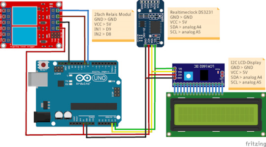
zeitgesteuerte Schaltung mit dem Arduino UNO R3, RTC und LCD-Display Für den Aufbau der Schaltung habe ich nachfolgende Bauteile verwendet: - einen Arduino Nano V3* - ein USB-Datenkabel* - eine RTC DS3231* - ein I2C LCD-Display* - ein Relais Shield* - diverse Breadboardkabel*, - ein 400 Pin Breadboard*
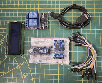
Arduino Nano V3, Relais Modul und RTC DS3231 sowie LC-Display Hinweis von mir: Die mit einem Sternchen (*) markierten Links sind Affiliate-Links. Wenn du über diese Links einkaufst, erhalte ich eine kleine Provision, die dazu beiträgt, diesen Blog zu unterstützen. Der Preis für dich bleibt dabei unverändert. Vielen Dank für deine Unterstützung!
Programm zum automatischen Schalten eines Relais zur gleichen Uhrzeit
Als Basis für dieses kleine Projekt verwende ich den bereits veröffentlichen Code zum Steuern eines Relais zu einem Zeitpunkt aus Datum und Uhrzeit. Diesen Code werden wir nun anpassen, um zu einer bestimmten Uhrzeit das Relais zu schalten. Klingt easy, ist es auch, wie du gleich sehen wirst. Programm: Zeitgesteuerte Schaltung mit RTC & Relaismodul für die tägliche SchaltungHerunterladen Im struct wo wir die Zeitpunkte zum Schalten der Relais definieren, kürzen wir das Datum hinaus. Relais relais1 = { 9, "Relais #1", { "", "14:22:00" }, { "", "14:22:10" } }; Relais relais2 = { 8, "Relais #2", { "", "14:22:05" }, { "", "14:22:15" } }; Die Funktion zum Prüfen der Zeitpunkte passen wir an und entfernen in den if-Bedingungen die Prüfungen auf das Datum. void checkCurrentTimestamp(Relais relais, Zeitstempel zeitstempel) { if (zeitstempel.zeit == relais.actionON.zeit) { Serial.println("aktivieren"); digitalWrite(relais.digitalPin, LOW); } else if (zeitstempel.zeit == relais.actionOFF.zeit) { Serial.println("deaktivieren"); digitalWrite(relais.digitalPin, HIGH); } } Das komplette Programm: //Bibliothek zum ansteuern des LCD-Display via I2C #include //Bibliothek für die kommunikation mit der RTC #include //Bibliothek zum kommunizieren mit dem //Bluetooth Modul über SoftwareSerial #include // I2C Adresse des RTC DS3231 #define RTC_I2C_ADDRESS 0x68 struct Zeitstempel { String datum; String zeit; }; struct Relais { int digitalPin; String desc; Zeitstempel actionON; Zeitstempel actionOFF; }; //Das Display wird über //die I2C Adresse 0x27 angesteuert //es hat 20 Zeichen pro Zeile //es hat 2 Zeilen LiquidCrystal_I2C lcd(0x27, 20, 2); char linebuf = {}; bool readData = false; Relais relais1 = { 9, "Relais #1", { "", "14:22:00" }, { "", "14:22:10" } }; Relais relais2 = { 8, "Relais #2", { "", "14:22:05" }, { "", "14:22:15" } }; // RX, TX SoftwareSerial btSerial(7, 6); void setup() { Serial.begin(9600); btSerial.begin(9600); //initialisieren des Displays lcd.init(); //aktivieren der Hintergrundbeleuchtung lcd.backlight(); pinMode(relais1.digitalPin, OUTPUT); pinMode(relais2.digitalPin, OUTPUT); digitalWrite(relais1.digitalPin, HIGH); digitalWrite(relais2.digitalPin, HIGH); } void loop() { readDataFromSerial(); if (readData) { String timestamp = linebuf; //Das Datum muss inkl. den Punkten 10 Zeichen lang sein String datum = timestamp.substring(0, 10); String tag = datum.substring(0, 2); String monat = datum.substring(3, 5); String jahr = datum.substring(6, 10); //Die Uhrzeit beginnt ab dem 11 Zeichen aus dem Zeitstempel String uhrzeit = timestamp.substring(11); String stunde = uhrzeit.substring(0, 2); String minute = uhrzeit.substring(3, 5); String sekunde = uhrzeit.substring(6); rtcWriteTimestamp(stunde.toInt(), minute.toInt(), stunde.toInt(), tag.toInt(), monat.toInt(), jahr.toInt()); } //bleibt leer Zeitstempel zeitstempel = readRtc(); lcd.setCursor(0, 0); lcd.print(zeitstempel.datum); lcd.setCursor(0, 1); lcd.print(zeitstempel.zeit); checkCurrentTimestamp(relais1, zeitstempel); checkCurrentTimestamp(relais2, zeitstempel); delay(500); } void checkCurrentTimestamp(Relais relais, Zeitstempel zeitstempel) { if (zeitstempel.zeit == relais.actionON.zeit) { Serial.println("aktivieren"); digitalWrite(relais.digitalPin, LOW); } else if (zeitstempel.zeit == relais.actionOFF.zeit) { Serial.println("deaktivieren"); digitalWrite(relais.digitalPin, HIGH); } } void readDataFromSerial() { //Zähler für die Zeichen byte counter = 0; readData = false; //Wenn Daten verfügbar sind dann... if (btSerial.available() > 0) { delay(250); readData = true; //solange Daten von der seriellen Schnittstelle //empfangen werden... while (btSerial.available()) { //speichern der Zeichen in dem Char Array char c = btSerial.read(); if (c != 'n') { linebuf = c; if (counter counter++; } } } Serial.println(linebuf); } } void rtcWriteTimestamp(int stunde, int minute, int sekunde, int tag, int monat, int jahr) { Wire.beginTransmission(RTC_I2C_ADDRESS); Wire.write(0); // Der Wert 0 aktiviert das RTC Modul. Wire.write(decToBcd(sekunde)); Wire.write(decToBcd(minute)); Wire.write(decToBcd(stunde)); Wire.write(decToBcd(0)); // Wochentag unberücksichtigt Wire.write(decToBcd(tag)); Wire.write(decToBcd(monat)); Wire.write(decToBcd(jahr - 2000)); Wire.endTransmission(); } //auslesen der Daten von der RealtimeClock Zeitstempel readRtc() { //Aufbau der Verbindung zur Adresse 0x68 Wire.beginTransmission(RTC_I2C_ADDRESS); Wire.write(0); Wire.endTransmission(); Wire.requestFrom(RTC_I2C_ADDRESS, 7); int sekunde = bcdToDec(Wire.read() & 0x7f); int minute = bcdToDec(Wire.read()); int stunde = bcdToDec(Wire.read() & 0x3f); int wochentag = bcdToDec(Wire.read()); int tag = bcdToDec(Wire.read()); int monat = bcdToDec(Wire.read()); int jahr = bcdToDec(Wire.read()) + 2000; char datum; sprintf(datum, "d.d.", tag, monat, jahr); char zeit; sprintf(zeit, "d:d:d", stunde, minute, sekunde); return { datum, zeit }; } //Convertiert Dezimalzeichen //in binäre Zeichen. byte decToBcd(byte val) { return ((val / 10 * 16) + (val % 10)); } //Convertiert binäre Zeichen in Dezimal //Zeichen. byte bcdToDec(byte val) { return ((val / 16 * 10) + (val % 16)); } Read the full article
0 notes
Text
Esplora HC-05 Bluetooth - Remote control
Esplora HC-05 Bluetooth – Remote control
Vamos a desbloquear alguna de las posibilidades que ofrece la placa Esplora. La placa Esplora contiene muchas opciones de control que no traen consigo otras placas. Al parecer, esta placa no consigue arrancar con proyectos que puedan llamar mucho la atención, pero para ello, voy a mostrar un ejemplo de uso que puede extenderse con muchas posibilidades. La idea concreta es poder realizar una…
View On WordPress
1 note
·
View note
Video
instagram
SO CLOSE. Using the hilt’s data line to turn on/off LED via the hilt’s “power” reed switch, using softwareSerial. #Arduino powers LED when there’s data in the buffer, but adding Delay to remove blinking makes the buffer drain too slowly. #galaxysedge #savisworkshop #electronics #makerspace #LEDbyExample #customlightsaber (at Burbank Makerspace) https://www.instagram.com/p/BznutFzHESv/?igshid=1ndmh603h3mxw
1 note
·
View note
Text

Justin Campoverde
Zoetrope
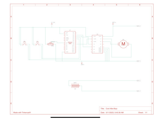
My final project consists of a zoetrope powered by a dc motor using an h-bridge. It has a button that turns it on or off and to change directions, and it has a potentiometer to make it go faster and slower

Parts

Code
#include "SoftwareSerial.h"
SoftwareSerial mySerial(10, 11);
# define Start_Byte 0x7E
# define Version_Byte 0xFF
# define Command_Length 0x06
# define End_Byte 0xEF
# define Acknowledge 0x00 //Returns info with command 0x41 [0x01: info, 0x00: no info]
# define ACTIVATED LOW
int buttonNext = 2;
int buttonPause = 3;
int buttonPrevious = 4;
boolean isPlaying = false;
void setup () {
pinMode(buttonPause, INPUT);
digitalWrite(buttonPause,HIGH);
pinMode(buttonNext, INPUT);
digitalWrite(buttonNext,HIGH);
pinMode(buttonPrevious, INPUT);
digitalWrite(buttonPrevious,HIGH);
mySerial.begin (9600);
delay(1000);
playFirst();
isPlaying = true;
}
void loop () {
if (digitalRead(buttonPause) == ACTIVATED)
{
if(isPlaying)
{
pause();
isPlaying = false;
}else
{
isPlaying = true;
play();
}
}
if (digitalRead(buttonNext) == ACTIVATED)
{
if(isPlaying)
{
playNext();
}
}
if (digitalRead(buttonPrevious) == ACTIVATED)
{
if(isPlaying)
{
playPrevious();
}
}
}
Alternate (that worked)

Code
int motor=9;
void setup() {
pinMode(motor, OUTPUT);
}
void loop() {
digitalWrite(motor, HIGH);
}
0 notes
Text
Harley-Davidson's updated Serial 1 e-bikes will feature Google Cloud connectivity - The Verge
Harley-Davidson's updated Serial 1 e-bikes will feature Google Cloud connectivity – The Verge
Filed under:E-bikes are going big on softwareSerial 1, the electric bike company spun out of Harley-Davidson, launched its second-generation lineup of premium e-bikes — but the biggest changes will be coming to the company’s app. The updated bikes will come with a host of new software features provided by Serial 1’s new partnership with Google Cloud. The company says that Google Cloud has…
View On WordPress
0 notes
Text
Bluetooth AT commands
- Parts used
Bluetooth HC-05 module
1x 1k resistor
1x 2k resistor
Jumper wires
Arduino
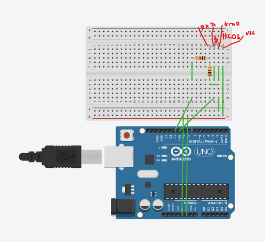
Photo of circuit:

Renaming the bluetooth module:

Code:
SoftwareSerial BTSerial(10, 11); // RX | TX
void setup() {
Serial.begin(9600); Serial.println("Enter AT commands:"); BTSerial.begin(38400); // HC-05 default speed in AT command }
void loop() {
if (BTSerial.available()) { // read from HC-05 and send to Arduino Serial Monitor Serial.write(BTSerial.read()); }
if (Serial.available()) { // Keep reading from Arduino Serial Monitor and send to HC-05 BTSerial.write(Serial.read()); }
Explanation:
The two resistors are used as a way of dividing voltage, since the receiver (RXD) pin of the only accepts 3.3v and the output of the pins on the Arduino is 5v, this is done to prevent overvoltage.
The inclusion of the software serial means that instead of using the TX / RX (pin 0 / 1) which can cause problems when trying to upload new code, you can use the PWM pins to replicate this and avoid issues. (on the final project, since the duck doesn’t need usb access whilst being used, the 0/1 pin will be used)
Troubleshooting required: See difficulties others may encounter
Evaluation: My first adventure into wireless communications was far more successful than i thought it would be, I genuinely thought that it would be more difficult than it was. something i could have improved is making some kind of basic call and response in the program using a switch just to extend my skills a small amount.
Difficulties others may encounter: Initially i used the TX/RX pin 0/1 on the Arduino, not realising this would cause issues with the board, to remedy this you can use the software serial function
0 notes
Text
Arduino und DS3231: Relais jeden Tag automatisch zur gleichen Uhrzeit schalten

In meinem bereits veröffentlichten Beitrag Zeitgesteuerte Schaltung mit Arduino: Programmieren von RTC, LCD und Relaismodul habe ich dir erläutert, wie man ein Relais via Zeitstempel aktivieren / deaktivieren kann. Dieser kleine Beitrag soll den Beitrag ergänzen und aufzeigen, wie man einen täglichen Timer erstellen kann, um automatisch jeden Tag zur gleichen Uhrzeit ein Relais zu aktivieren oder zu deaktivieren. https://youtu.be/FjLisNBPAV0 Diese Schaltung kannst du zum Beispiel auch nutzen, um deine Weihnachtsbaumbeleuchtung zu schalten.
Rückblick - Relais & RTC DS3231 am Arduino UNO R3
Schauen wir uns kurz noch einmal die Schaltung am Arduino UNO R3 an:

zeitgesteuerte Schaltung mit dem Arduino UNO R3, RTC und LCD-Display Für den Aufbau der Schaltung habe ich nachfolgende Bauteile verwendet: - einen Arduino Nano V3* - ein USB-Datenkabel* - eine RTC DS3231* - ein I2C LCD-Display* - ein Relais Shield* - diverse Breadboardkabel*, - ein 400 Pin Breadboard*

Arduino Nano V3, Relais Modul und RTC DS3231 sowie LC-Display Hinweis von mir: Die mit einem Sternchen (*) markierten Links sind Affiliate-Links. Wenn du über diese Links einkaufst, erhalte ich eine kleine Provision, die dazu beiträgt, diesen Blog zu unterstützen. Der Preis für dich bleibt dabei unverändert. Vielen Dank für deine Unterstützung!
Programm zum automatischen Schalten eines Relais zur gleichen Uhrzeit
Als Basis für dieses kleine Projekt verwende ich den bereits veröffentlichen Code zum Steuern eines Relais zu einem Zeitpunkt aus Datum und Uhrzeit. Diesen Code werden wir nun anpassen, um zu einer bestimmten Uhrzeit das Relais zu schalten. Klingt easy, ist es auch, wie du gleich sehen wirst. Programm: Zeitgesteuerte Schaltung mit RTC & Relaismodul für die tägliche SchaltungHerunterladen Im struct wo wir die Zeitpunkte zum Schalten der Relais definieren, kürzen wir das Datum hinaus. Relais relais1 = { 9, "Relais #1", { "", "14:22:00" }, { "", "14:22:10" } }; Relais relais2 = { 8, "Relais #2", { "", "14:22:05" }, { "", "14:22:15" } }; Die Funktion zum Prüfen der Zeitpunkte passen wir an und entfernen in den if-Bedingungen die Prüfungen auf das Datum. void checkCurrentTimestamp(Relais relais, Zeitstempel zeitstempel) { if (zeitstempel.zeit == relais.actionON.zeit) { Serial.println("aktivieren"); digitalWrite(relais.digitalPin, LOW); } else if (zeitstempel.zeit == relais.actionOFF.zeit) { Serial.println("deaktivieren"); digitalWrite(relais.digitalPin, HIGH); } } Das komplette Programm: //Bibliothek zum ansteuern des LCD-Display via I2C #include //Bibliothek für die kommunikation mit der RTC #include //Bibliothek zum kommunizieren mit dem //Bluetooth Modul über SoftwareSerial #include // I2C Adresse des RTC DS3231 #define RTC_I2C_ADDRESS 0x68 struct Zeitstempel { String datum; String zeit; }; struct Relais { int digitalPin; String desc; Zeitstempel actionON; Zeitstempel actionOFF; }; //Das Display wird über //die I2C Adresse 0x27 angesteuert //es hat 20 Zeichen pro Zeile //es hat 2 Zeilen LiquidCrystal_I2C lcd(0x27, 20, 2); char linebuf = {}; bool readData = false; Relais relais1 = { 9, "Relais #1", { "", "14:22:00" }, { "", "14:22:10" } }; Relais relais2 = { 8, "Relais #2", { "", "14:22:05" }, { "", "14:22:15" } }; // RX, TX SoftwareSerial btSerial(7, 6); void setup() { Serial.begin(9600); btSerial.begin(9600); //initialisieren des Displays lcd.init(); //aktivieren der Hintergrundbeleuchtung lcd.backlight(); pinMode(relais1.digitalPin, OUTPUT); pinMode(relais2.digitalPin, OUTPUT); digitalWrite(relais1.digitalPin, HIGH); digitalWrite(relais2.digitalPin, HIGH); } void loop() { readDataFromSerial(); if (readData) { String timestamp = linebuf; //Das Datum muss inkl. den Punkten 10 Zeichen lang sein String datum = timestamp.substring(0, 10); String tag = datum.substring(0, 2); String monat = datum.substring(3, 5); String jahr = datum.substring(6, 10); //Die Uhrzeit beginnt ab dem 11 Zeichen aus dem Zeitstempel String uhrzeit = timestamp.substring(11); String stunde = uhrzeit.substring(0, 2); String minute = uhrzeit.substring(3, 5); String sekunde = uhrzeit.substring(6); rtcWriteTimestamp(stunde.toInt(), minute.toInt(), stunde.toInt(), tag.toInt(), monat.toInt(), jahr.toInt()); } //bleibt leer Zeitstempel zeitstempel = readRtc(); lcd.setCursor(0, 0); lcd.print(zeitstempel.datum); lcd.setCursor(0, 1); lcd.print(zeitstempel.zeit); checkCurrentTimestamp(relais1, zeitstempel); checkCurrentTimestamp(relais2, zeitstempel); delay(500); } void checkCurrentTimestamp(Relais relais, Zeitstempel zeitstempel) { if (zeitstempel.zeit == relais.actionON.zeit) { Serial.println("aktivieren"); digitalWrite(relais.digitalPin, LOW); } else if (zeitstempel.zeit == relais.actionOFF.zeit) { Serial.println("deaktivieren"); digitalWrite(relais.digitalPin, HIGH); } } void readDataFromSerial() { //Zähler für die Zeichen byte counter = 0; readData = false; //Wenn Daten verfügbar sind dann... if (btSerial.available() > 0) { delay(250); readData = true; //solange Daten von der seriellen Schnittstelle //empfangen werden... while (btSerial.available()) { //speichern der Zeichen in dem Char Array char c = btSerial.read(); if (c != 'n') { linebuf = c; if (counter counter++; } } } Serial.println(linebuf); } } void rtcWriteTimestamp(int stunde, int minute, int sekunde, int tag, int monat, int jahr) { Wire.beginTransmission(RTC_I2C_ADDRESS); Wire.write(0); // Der Wert 0 aktiviert das RTC Modul. Wire.write(decToBcd(sekunde)); Wire.write(decToBcd(minute)); Wire.write(decToBcd(stunde)); Wire.write(decToBcd(0)); // Wochentag unberücksichtigt Wire.write(decToBcd(tag)); Wire.write(decToBcd(monat)); Wire.write(decToBcd(jahr - 2000)); Wire.endTransmission(); } //auslesen der Daten von der RealtimeClock Zeitstempel readRtc() { //Aufbau der Verbindung zur Adresse 0x68 Wire.beginTransmission(RTC_I2C_ADDRESS); Wire.write(0); Wire.endTransmission(); Wire.requestFrom(RTC_I2C_ADDRESS, 7); int sekunde = bcdToDec(Wire.read() & 0x7f); int minute = bcdToDec(Wire.read()); int stunde = bcdToDec(Wire.read() & 0x3f); int wochentag = bcdToDec(Wire.read()); int tag = bcdToDec(Wire.read()); int monat = bcdToDec(Wire.read()); int jahr = bcdToDec(Wire.read()) + 2000; char datum; sprintf(datum, "d.d.", tag, monat, jahr); char zeit; sprintf(zeit, "d:d:d", stunde, minute, sekunde); return { datum, zeit }; } //Convertiert Dezimalzeichen //in binäre Zeichen. byte decToBcd(byte val) { return ((val / 10 * 16) + (val % 10)); } //Convertiert binäre Zeichen in Dezimal //Zeichen. byte bcdToDec(byte val) { return ((val / 16 * 10) + (val % 16)); } Read the full article
0 notes
Text
Differences between Read, ReadString and ReadStringUntil
Differences between Read, ReadString and ReadStringUntil
Desde nuestro monitor serie disponemos de un cable para enviar información y otro para recibirla. En la gran mayoría de casos se envía información para conocer el estado de las variables dentro de un programa para poder conocer como se gestionan durante la ejecución del mismo. Pero muy pocas veces se utilizan para leer datos a menos que creemos una comunicación Bluetooth para recibir datos de…
View On WordPress
#Bluetooth#buffer#CR#CRLF#LF#Monitor Serial#read#ReadString#ReadStringUntil#Salto de linea#Serial#SoftwareSerial#Text
0 notes
Text
Background To Stone Technology And Setting Up RGB Control
In the previous post, we all seen basics of STONE TFT display interface and how to use for our embedded application, in this post we will be going to use same display for control our RGB led strip and we going to ON or OFF light using a display touch interface, so let's get started with the setup of our new project.
For our setup we required.
STONE TFT display
Display USB cable for programming.
Arduino UNO
Some wires for connection.
WS2812 LED strip
12V or 5V DC supply.
RS323 to TTL
So I already have all set up with me, i will first prepare STONE HMI UI.
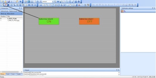
So we go to HMI display TOOL4.3 and start a new project call RGB_LED, and add an image which includes our 2 buttons ON/OFF.
Step 1: we create one image with background and 2 buttons ON and OFF, shown as below image and add as an image in our project.
Step 2: And then we add return press by key-value shape over our button shape, this is basically control which is going to send some hex value to our Arduino board when someone is touch this button shape, we do this same off OFF button also.
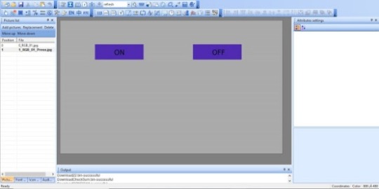
Step 3: Now we need to indicate user also so he/she comes to know he touched button so we need to add button effect on press for that we need to add an image with updated color code of button to blue,
we create this image in some image editor and add a picture as a jpg file to out software.
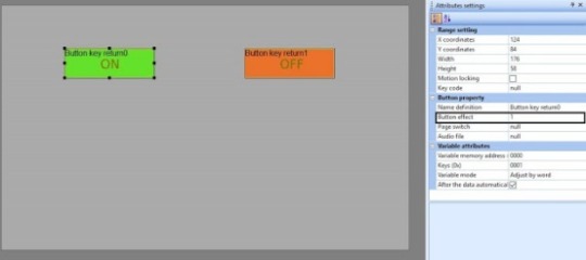
Step 4: So we already add our effect image in tool now we need to config it, so for that, we are going to update our button property for that, you need to click to button square box and then go to right side Atributr setting window, in that button property you get one member called "Button effect", this setting you need to select our second image from drag and drop menu.
Step 5: And for identifying both button event we need to provide key-value fro both button and it should be Unique hex number, as we have only 2 buttons we provide key for ON=01 and OFF=02.
Step 6: Need to build and download this project to out HMI display, i think you all already gone three my previous tutorial part-1, all process-related that is already explained in this tutorial.
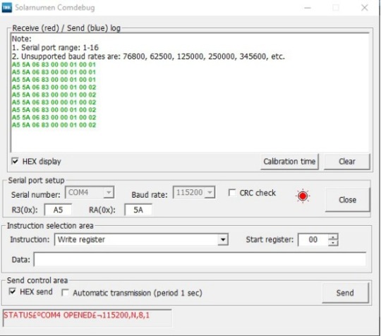
Step 7: We need to test the button press event next data with our tool to ensure what we configured is working or not before the jump to the Arduino project, so for that, you just need to plug HMO display with the serial module and then connect this serial module to your PC and click to serail icon as shown in below screen, you will get one popup screen on that you need to select the appropriate serial port and click on open, after that you need to touch to display button when you touch to button you will get on hex stream on display, the last byte of the stream is key of a button which you set in the project.
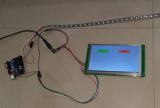
Now our display setup is done we need to set up our Arduino board hardware first, set up hardware as below image.
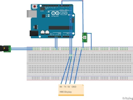
Now time to code our Arduino as per Hex stream which we tested, and also we need to control our LED strip also.
For programming, we are going to use platform IO with the VS code, i am like this setup because it is convenient to use.
This is Code i made for this project.
main.c
1
2
3
4
5
6
7
8
9
10
#include <Arduino.h>#include <Adafruit_NeoPixel.h>#include <SoftwareSerial.h>
#define PIN 6
SoftwareSerial softserial(2, 3);
Adafruit_NeoPixel strip = Adafruit_NeoPixel(60, PIN, NEO_GRB + NEO_KHZ800);char RxData[15];unsigned char arrIndex = 0;unsigned char index = 0;
void setup() {
Serial.begin(115200);
softserial.begin(115200);
11
12
13
14
15
16
17
18
19
20
21
22
23
24
25
26
27
28
29
30
31
32
33
34
35
36
37
38
39
40
41
42
43
44
45
strip.begin();
strip.show();
}
void loop() {
if(softserial.available())
{
RxData[arrIndex] = softserial.read();
//Serial.print(RxData[arrIndex]);
arrIndex++;
if (arrIndex >= 9) {
if(RxData[8] == 0x01)
{
strip.fill(strip.Color(255, 255, 255), 0, 60);
strip.show();
}
if(RxData[8] == 0x02)
{
strip.clear();
strip.show();
}
for(int i = 0; i < 9; i++)
{
Serial.print(RxData[i]);
}
arrIndex = 0;
}
}
}
platformio.ini
1
2
3
4
5
[env:uno]
platform = atmelavr
board = uno
framework = arduino
lib_deps = Adafruit NeoPixel
Now just use the above code and build and program you Arduino Uno.
This is a video of the final test of our project.
https://youtu.be/uWgysGXv8fs
0 notes
Photo

I think there’s a bug in HerkuleX DRS-0101 smart servo’s firmware. Workaround.
First of all – I love these servos. There’s a great user manual, small sized, an enormous number of features, etc. etc.
But there was one issue I've finally solved! Maybe two. The second one is that there is not much information about this servo in the Net. Some people have been faced the same problem. So I decided to share my humble experience.
But - in order… The first quest was to find a library to use it in my code. I found one dead Python project, some more or less alive Arduino libraries and one C++ Windows library (with dll and with no source code). My plan was to control HerkuleX servos in C++ ROS node, so Python was my plan “B”, Windows library was useless in Ubuntu, and the only suitable way was to edit the open source Arduino library. Of course, I could write my own library from scratch, but that’s the warrior’s way.
I think I had chosen one of the most popular Arduino library and the only thing I changed in it was the implementation of serial port communication since it is very “Arduino oriented”. When the library was completed, I included it in my code and all functions I’d used were working fine except one… GetAngle() was unstable. Sometimes it worked correctly, sometimes it returned -166.72°.
I tried three servos HerkuleX DRS-0101 with the same result. It was definitely a software issue.
I dived deep into the servo’s manual and attentively checked the code of GetAngle() function. It seemed everything is fine with the function. So I wrote a Python script to send data packets to the servo and receive response packets from it. Finally, I noticed that sometimes packets with the servo’s position have wrong size byte.
Here is a “good” packet:
FF FF 0D FD 44 B2 4C 3A 02 1F 62 00 42
And this is a broken one:
FF FF 0A FD 44 B2 4C 3A 02 1F 62 00 42
First two bytes are the header.
0D(13) is the length of the packet. 13 – exactly the size of this sequence of bytes. And 0A(10) – is the core of my problem.
FD is the servo’s unique identifier.
44 identifies the response on Read RAM command.
B2 – checksum1 (bold text).
4C – checksum2 (bold text).
3A – address in the RAM Registry we are reading (address of the current calibrated position).
02 – number of bytes we are reading.
1F 62 – the servo’s angle (I’ll explain these numbers in a moment).
00 – status error (0 is a good sign).
42 – status detail.
Just a short off-topic about 1F 62 value. These two bytes are a flipped 2-byte integer 0x621F. Significant bits for calibrated servo position is 10 lowest bits, so the final value is 0x021F. To get the angle in degrees we can use the table in the manual or just calculate this expression:
(0x021F - 512) * 0.325 = (543 - 512) * 0.325 = 10.075°.
So when the servo sends a packet with the wrong length byte, the GetAndle() function fails while testing the packet’s checksums. The returned value -166.72 is a consequence of this fail.
The thing is that if we change the length byte from 0A to 0D, the checksums will be correct! Note that checksums in both correct and broken packets are the same. I believe that there is a bug in servo’s firmware that this byte with the packet’s length value sometimes is not set and it is filled with garbage. That’s why sometimes GetAngle() works, sometimes doesn’t.
I checked the firmware version in my servos: 090. Unfortunately, it’s the latest available firmware. It is dated May 10, 2012. What is the manufacturer waiting for? Today it is December 2017.
And now the worst thing. GetAngle() is a high-level function from Arduino library that reads two bytes from RAM Register starting with address 0x3A. I mean that GetAngle() uses a low-level firmware function that reads data from RAM Register. So I assume that reads of any other RAM Register addresses don't work properly either.
That's the time for good news. Here is the workaround I promised in the title. We can change the byte with the packet length in the received data packet. Only one single byte. After that, both checksums will become valid.
Here is the original Arduino library I’ve used. User Rambo made a GitHub copy and some improvements in it and I made a fork just to fix the firmware bug. See the changes in my GitHub commit.
By the way. There’s another issue with this library while running on Arduino Uno. It uses SoftwareSerial, thereby I noticed the communication is unstable on 115200 baud rate and should be reduced to 57600. But that’s another story.
1 note
·
View note
Text
CC Lab : Rain Pillow
A smart pillow that automatically plays white noise – rainy sound to soothe you and help you get a better sleep. The pillow works automatically when the room is dark and your head is laid on the pillow. Photoresistor acts light sensor to detect lighting condition in your bedroom while the pressure sensor is put together by using velostat mat in between 2 sheets of conductive fabric. The rain sound is a mp3 file installed in a micro sd card inside DFplayer which is connected to 8 ohm mini speaker.
youtube


Below is my entire Arduino codes.
#include "Arduino.h" #include "SoftwareSerial.h" #include "DFRobotDFPlayerMini.h"
int pinSound = 9; int pinLight = A0; int pinPress = A4; bool isPlayed = false;
int lightVal; int pressVal;
SoftwareSerial mySoftwareSerial(6, 5); // RX, TX DFRobotDFPlayerMini myDFPlayer; void printDetail(uint8_t type, int value);
void setup() {
pinMode(pinSound, OUTPUT); pinMode(pinLight, INPUT); pinMode(pinPress, INPUT); mySoftwareSerial.begin(9600); Serial.begin(115200);
Serial.println(); Serial.println(F("DFRobot DFPlayer Mini Demo")); Serial.println(F("Initializing DFPlayer ... (May take 3~5 seconds)"));
if (!myDFPlayer.begin(mySoftwareSerial)) { //Use softwareSerial to communicate with mp3. Serial.println(F("Unable to begin:")); Serial.println(F("1.Please recheck the connection!")); Serial.println(F("2.Please insert the SD card!")); while (true); } Serial.println(F("DFPlayer Mini online."));
myDFPlayer.volume(20); //Set volume value. From 0 to 30 // myDFPlayer.play(1); //Play the first mp3 }
void loop() { static unsigned long timer = millis();
lightVal = analogRead(pinLight); pressVal = analogRead(pinPress);
Serial.print(lightVal); Serial.println(pressVal);
if (lightVal > 900 && pressVal >900 && !isPlayed) { timer = millis(); myDFPlayer.play(); //Play next mp3 every 3 second. isPlayed = true; } else if( lightVal < 800 && pressVal < 150) { isPlayed = false; myDFPlayer.stop(); }
if (myDFPlayer.available()) { printDetail(myDFPlayer.readType(), myDFPlayer.read()); //Print the detail message from DFPlayer to handle different errors and states. } }
1 note
·
View note
Text
Pinos virtuais Blynk

A aplicação "Blynk" dispõem de 3 tipos diferentes de pinos. Todos conhecemos os pinos físicos GPIO (analógicos e digitais), mas o aplicativo oferece mais um tipo de pinos e hoje vamos aprender quando e como os devemos usar. Diferença entre pinos digitais, analógicos e virtuais na aplicação Geralmente, a grande maioria dos projetos utiliza apenas entradas e saídas analógicas ou digitais, mas quando falamos no controlo de um projeto via internet através da app "Blynk", surge um novo tipo de entradas, as entradas virtuais.

Estas entradas distinguem-se das restantes dentro do aplicativo pois permitem ao utilizador realizar um tratamento de dados dentro do programa antes de os reproduzir no aplicativo, vejamos um exemplo: Para registar os valores da luminosidade dentro de uma sala via arduino, recorremos a um LDR que utiliza um intervalo que varia entre 0-1023. Para apresentar estes valores no aplicativo através de um gráfico, torna-se mais "aceitável" transformar o intervalo de 0-1023 para um intervalo que varia entre 0-100%. Para resolver o seguinte exemplo vamos seguir os seguintes passos: Esquema de ligações:

Código de programação: /************Definição das librarias responsáveis pela comunicação com a app************/ #define BLYNK_PRINT Serial #include #include #include SoftwareSerial EspSerial(2, 3); // RX, TX /*******Definição do TOKEN do projeto*******/ char auth = "AUTH TOKEN"; /************ Credênciais WIFI ************/ //Em caso de redes abertas deixar "" char ssid = "Rede WIFI"; char pass = "PASSWORD"; // definição da baud do ESP8266 como 9600 #define ESP8266_BAUD 9600 ESP8266 wifi(&EspSerial); BlynkTimer timerLDR; // Criação do Timer do LDR void lerLDR() // Função para ler o parâmetro do LDR { int valorLDR = analogRead(A0); valorLDR = map(valorLDR, 0, 1023, 0, 100); // Função que permite a conversão do intervalo de 0-1023 para 0-100 Blynk.virtualWrite(V6, valorLDR); // Escreve no pino virtual V6 do Blynk o valor de luminosidade lido pelo LDR } void setup() { Serial.begin(9600); //Inicialização do ESP8266 EspSerial.begin(ESP8266_BAUD); delay(10); Blynk.begin(auth, wifi, ssid, pass); timerLDR.setInterval(100L, lerLDR); // Define o intervalo de tempo da leitura do LDR para 100 milissegundos } void loop() { Blynk.run(); timerLDR.run(); } Configuração da aplicação: Continuando com o esquema do ultimo artigo, vamos alterar apenas o "Gauge" do LDR.


Resultado Final: Lista de Material: Todos os produtos foram adquiridos na loja de eletrónica e robótica ElectroFun: www.electrofun.pt. Arduino UNO Led LDR Breadboard Resistências Buzzer Ativo Wire Jumpers Kit Arduino Iniciação (opcional) Gostaram deste artigo? Deixem o vosso comentário no formulário a baixo e partilhem com os vossos amigos. Não se esqueçam de fazer like na nossa Página no Facebook. Podem ainda colocar as vossas dúvidas no nosso Forum da Comunidade Arduino em Portugal ou no nosso Grupo no Facebook Arduino Portugal – Qual o teu projeto? Read the full article
0 notes
Text
Bluetooth Setup (HC-05 Bluetooth Module)
- Parts used
HC-05 Bluetooth Module
1x 1k Resistor
1x 2k Resistor
Arduino
Jumper Wires
Photo of circuit & software:


Code:
#include <SoftwareSerial.h>
SoftwareSerial Bluetooth(10, 11); // RX | TX
void setup() { Serial.begin(9600); Bluetooth.begin(9600); }
void loop() { if (Bluetooth.available()) Serial.write(Bluetooth.read()); if (Serial.available()) Bluetooth.write(Serial.read()); }

(Ignore the use of the RGB LED, its because it had 4 pins and sits similarly to the HC05 - i have noted which pins are which above it)
Explanation:
The two resistors are used as a way of dividing voltage, since the receiver (RXD) pin of the only accepts 3.3v and the output of the pins on the Arduino is 5v, this is done to prevent overvoltage.
The inclusion of the software serial means that instead of using the TX / RX (pin 0 / 1) which can cause problems when trying to upload new code, you can use the PWM pins to replicate this and avoid issues. (on the final project, since the duck doesn’t need usb access whilst being used, the 0/1 pin will be used)
Troubleshooting required: See difficulties others may encounter
Evaluation: My first adventure into wireless communications was far more successful than i thought it would be, I genuinely thought that it would be more difficult than it was. something i could have improved is making some kind of basic call and response in the program using a switch just to extend my skills a small amount.
Difficulties others may encounter: Initially i used the TX/RX pin 0/1 on the Arduino, not realising this would cause issues with the board, to remedy this you can use the software serial function
0 notes
Link
La programación de código abierto sigue avanzando para ofrecernos una amplia gama de aplicaciones mediante microcontroladores. Desde su concepción en 2005, las placas Arduino MEGA, UNO y otras variantes ofrecen diferentes prestaciones. Aprenda cómo elegir la placa Arduino que necesita con la opinión de nuestros expertos.
Placas Arduino según las necesidades de su proyecto
Más allá de los clones, como Netduino o Freeduino, una placa Arduino Mega u otro modelo original lleva la marca comercial impresa en el circuito. Al momento de elegir este componente electrónico para su proyecto, le recomendamos considerar:
Precio
Arquitectura
Número de pines
Propósito general
Consumo de energía
Disponibilidad en el mercado
Clases de programadores para el proyecto
Herramientas de depuración, IDE y compiladores
Capacidad de memoria flash, EMPROM, ROM o RAM
Cantidad de interruptores comparadores, ADC, DAC y PMW
Tipos de placas Arduino para su proyecto
De acuerdo a los criterios anteriores, la elección de la placa Arduino ideal requiere de un análisis previo para encontrar el modelo que se ajuste a las necesidades de su prototipo. Entre la amplia variedad de microcontroladores disponibles en México y el mercado, destacan:
Arduino o Genuino Uno R3. Con un costo muy accesible, estas piezas electrónicas están diseñadas para principiantes y quienes ya manejan un nivel intermedio. Es una placa de propósito general, por eso cuenta con 20 pines GPIO (14 digitales y 6 analógicos). Cuenta con 2 versiones principales: chip SMD soldado y normal (removible). También incluye pasadores Tx y Rx para conectar dispositivos en serie, siendo posible agregar éstos por separado mediante el SoftwareSerial.
Arduino Pro Mini. Parecida a la anterior pero más barata, esta placa de programación tiene las mismas prestaciones que la anterior. Por ello, dispone de un microcontrolador ATmega328p, el cual es totalmente compatible en hardware y software con el modelo UNO o el mega2560. Su función principal es abaratar costos por tener 3 cm de largo, no incluir pines ni contar con opción USB.
Arduino Mega. Ideal para un proyecto más complejo, este componente electrónico te ofrece 4 puertos de serie de hardware (UARTs), 16 entradas analógicas y 54 pines digitales de entrada/salida. También incluye líneas SDA, ACL y AREF, conexión USB, oscilador de 16 MHz, cabecera ICSP, botón de reinicio y conector de energía. Compatible con la UNO y la mayoría de shields (escudos), sirve para robótica o domótica.
Arduino Lilypad. Esta placa tiene la particularidad que se utiliza para la tecnología de “wereables”. Esto se logra con el uso de shields especializados e hilo conductor para integrarla a la vestimenta que se quiere modificar.
Arduino Yun. Basada en el ATmega32u4 y el Atheros AR9331, posee 20 pines, puerto USB-A, soporte para Internet y WiFi, conexión micro USBA y 3 botones de reinicio. Cuenta con una funcionalidad bajo Linux que facilita los prototipos para el IoT.
Si no encuentra el microcontrolador que necesita en esta lista, no se preocupe. Además de la Arduino MEGA, en Electrónicos CDMX tenemos muchos modelos para su proyecto. Contáctenos al teléfono y WhatsApp: 55 1568 4524.
0 notes
Text
Arduino Joystick Shield: Daten per Bluetooth versenden – So geht's!

In diesem kurzen Beitrag möchte ich dir gerne zeigen, wie du Daten des Joystick Shield am Arduino via Bluetooth versenden kannst. Im letzten Beitrag habe ich dir bereits dieses Shield vorgestellt und gezeigt, wie man die Daten der Joysticks abgreifen kann. Hier soll es nun darum gehen, wie du diese Daten via Bluetooth versenden kannst. https://youtu.be/cqPeGtMyXnw Ich baue hier auf den Beitrag Arduino Joystick Shield Basics: Programmierung leicht gemacht für Anfänger auf, solltest du diesen also nicht kennen, dann empfehle ich dir zunächst dort einmal hereinzuschauen, damit du die Basics zu diesem Shield kennst.


Bluetoothkommunikation mit dem Arduino
Mit dem Arduino kannst du sehr einfach über Bluetooth 4.x funken, denn die entsprechenden Module werden einfach via serieller Schnittstelle eingebunden und die Daten werden dann darüber gesendet und empfangen. Wenn du jedoch über Bluetooth Low Energy kurz BLE funken möchtest, dann wird es etwas komplizierter / umfangreicher. In diesem Beitrag versende ich die Daten via Bluetooth 4.x und somit ist das Beispiel besonders für Anfänger geeignet.

Schaltung - Arduino UNO R3 mit Bluetooth Modul HC-06 Das Bluetooth Module HC-06 habe ich dir bereits im separaten Beitrag Arduino Lektion 21: Bluetooth Modul HC-06 vorgestellt.
Einstecken und Programmieren des Bluetooth Moduls am Joystick Shield
Stecken wir zunächst das Bluetooth Modul HC-06 in das Joystick Shield ein. Dabei müssen wir darauf achten, dass die Datenpins RX & TX auf die digitalen Pins D13 & D12 zeigen.

Bluetooth Modul HC-06 am Arduino Joystick Shield

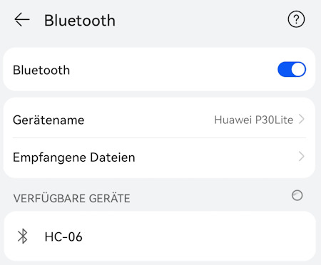
Rückseite des Bluetooth Modul HC-06 am Arduino Joystick Shield Die Programmierung erfolgt wie erwähnt über die serielle Schnittstelle in diesem Fall eher über SoftwareSerial. Dieses Feature ist Bestandteil der Arduino IDE du musst quasi für die Beispiele keine zusätzlichen Pakete installieren. //Einbinden der Bibliothek für die serielle Kommunikation //über andere digitale Pins als wie D0 & D1 #include //externe Datei mit der Funktion zum auslesen der Daten von //den Joysticks #include "joystick.h" //initialisieren eines SoftwareSerial Objektes //mit RX 12 und TX 13 SoftwareSerial softwareSerial(12, 13); void setup() { //begin der seriellen Kommunikation mit 9600 baud softwareSerial.begin(9600); } void loop() { //Wenn Daten an der seriellen Schnittstelle anliegen, //dann ... if (softwareSerial.available() > 0) { //auslesen der Daten von der seriellen Schnittstelle, //als gesamte Zeile String data = softwareSerial.readString(); //Entfernen der unnötigen Leerzeichen, Leerzeilen am Anfang //und Ende der Daten. data.trim(); //Wenn der Wert "get" in der Variable data steht, dann... if (data == "get") { //Auslesen der aktuellen Daten der Joysticks und //senden über die SoftwareSerial Schnittstelle softwareSerial.println(getJoyStickValues()); //Die Zeile wird mit einem Zeilenumbruch beendet! } } } Den kompletten Code zu diesem Beispiel findest du in der nachfolgenden ZIP-Datei. Code - senden der Daten von den Joysticks via BluetoothHerunterladen Was nun noch fehlt, ist ein Empfänger, hier kann man verschiedene andere Mikrocontroller wie einen Calliope Mini 3, ESP32 oder auch einen Raspberry Pi verwenden. Jedoch um diesen Beitrag so einfach wie möglich zu halten verwende ich mein Android Handy mit der App Serial Bluetooth Terminal. Zunächst muss die Verbindung mit dem Bluetooth Modul HC-06 hergestellt werden (das Passwort ist 1234).

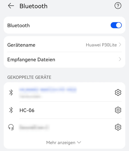
In der App Serial Bluetooth Terminal muss jetzt nur noch das Gerät ausgewählt und eine Verbindung hergestellt werden. Im nächsten Schritt kann man jetzt einen Text senden, welcher vom Arduino empfangen und ausgewertet wird. In meinem Fall sende ich ein get und empfange dann die aktuellen Positionsdaten der Joysticks im JSON Format.
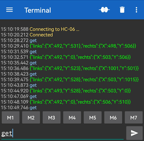
Android App - Serial Bluetooth Terminal Read the full article
0 notes