#Velocity Feedback Transmitters
Explore tagged Tumblr posts
Visit Tumblr Blog
Explore Tumblr blogs with no restrictions, modern design and the best experience.
Last Seen Tumblr Blogs


Fun Fact
Tumblr’s reach among the 26-to-35-year-olds in the US is 11%.
Text
Unveiling the Power of Position Velocity Feedback Transmitter Systems in Modern Industries

Introduction: The Importance of Position and Velocity Feedback Systems in Precision Control
Position and velocity feedback transmitter systems are integral to industries that demand high-precision control and motion tracking. These systems are employed to monitor the position and velocity of moving objects in real-time, providing critical data for automated operations. The evolution of these systems has been significant, with advancements in technology enabling more compact, accurate, and reliable feedback mechanisms that drive automation, robotics, aerospace, automotive, and healthcare applications.
With the global shift towards increased automation, the demand for such systems is on the rise. Industries across the board require precise control of machinery, vehicles, and robots to enhance performance, improve safety, and optimize productivity. The growing need for smart manufacturing, autonomous vehicles, and medical robotics underscores the vital role these systems play in modern industries. Despite some challenges, such as high upfront costs and integration complexities, the long-term benefits of precision, efficiency, and reliability outweigh these hurdles.
Request Sample Report PDF (including TOC, Graphs & Tables): https://www.statsandresearch.com/request-sample/40604-global-position-velocity-feedback-transmitter-systems-market
Position Velocity Feedback Transmitter Systems Market Dynamics: Drivers, Challenges, and Opportunities
Drivers of Growth
The Position Velocity Feedback Transmitter Systems market is experiencing robust growth driven by several key factors:
Advancements in Automation and Robotics: Industries across manufacturing, automotive, and aerospace are increasingly adopting automation technologies. These systems allow for faster, more accurate control, driving the need for precise position and velocity feedback.
Technological Advancements in Sensors: Innovations in sensor technology, particularly in digital systems, are facilitating the development of more accurate and miniaturized position velocity feedback systems. The integration of Internet of Things (IoT) technologies is making these systems smarter and more adaptable, driving their adoption in industries such as healthcare, smart manufacturing, and autonomous vehicles.
The Rise of Industry 4.0: Industry 4.0 technologies are revolutionizing production lines, with automation and data-driven decisions at their core. Position velocity feedback systems play a critical role in enabling smarter, more efficient manufacturing processes.
Emerging Applications in Healthcare and Autonomous Vehicles: In healthcare, robotic surgeries and diagnostics systems demand highly accurate motion control, while autonomous vehicles require precise feedback systems for safe operation. Both sectors are driving significant demand for position and velocity feedback systems.
Get up to 30% Discount: https://www.statsandresearch.com/check-discount/40604-global-position-velocity-feedback-transmitter-systems-market
Challenges to Position Velocity Feedback Transmitter Systems Market Adoption
Despite the promising growth, several barriers could slow the widespread adoption of position velocity feedback transmitter systems:
High Initial Investment Costs: The cost of acquiring and integrating high-precision position velocity feedback systems can be prohibitive, especially for small and medium-sized enterprises (SMEs). High upfront costs can deter organizations from upgrading or adopting these systems, limiting market expansion.
Complexity of System Integration: Integrating new feedback systems with existing infrastructure and machinery can be complex and time-consuming, especially in industries that have legacy systems. This complexity increases the time to market and may discourage immediate adoption.
Specialized Training Requirements: The operation, calibration, and maintenance of advanced position velocity feedback systems require highly specialized knowledge and skills. The shortage of skilled labor in these fields may hinder growth, particularly in developing regions.
Key Opportunities
Several emerging trends present substantial opportunities for the growth of the position velocity feedback transmitter systems market:
Smart Manufacturing: As manufacturing processes become increasingly automated, there is a growing demand for position velocity feedback systems to enhance productivity and reduce human error. These systems are integral to improving the efficiency of production lines and ensuring consistent product quality.
Healthcare Robotics: Surgical robots, diagnostic devices, and rehabilitation technologies require real-time motion control. The healthcare sector’s increasing reliance on these technologies provides a substantial opportunity for the growth of high-precision position feedback systems.
Autonomous Vehicles: The rapid development of autonomous vehicles (AVs) hinges on accurate motion tracking and feedback systems for safe navigation. As the demand for AVs increases, so too will the demand for position and velocity feedback transmitters that ensure precise vehicle control.
Position Velocity Feedback Transmitter Systems Market Segmentation and Analysis
By Type
The position velocity feedback transmitter systems market can be divided into two key types:
Position Feedback Transmitter: This sub-segment is expected to dominate the market, driven by the increasing demand for precision in industrial automation applications. Position feedback transmitters provide accurate location tracking, ensuring the correct placement of components in automated systems.
Velocity Feedback Transmitter: While this segment is smaller, it is growing rapidly due to the need for precise speed control in applications such as robotics, aerospace, and automotive industries.
By Technology
Analog Systems: While still in use, analog systems are being increasingly replaced by more sophisticated digital feedback systems that offer greater accuracy and scalability.
Digital Systems: Dominating the market, digital systems provide real-time, highly accurate feedback for a range of applications, particularly in industries like automotive, aerospace, and healthcare. The continued innovation in sensor technology and integration with IoT is expected to fuel further growth in this segment.
By Application
The demand for position and velocity feedback systems spans a variety of industries:
Industrial Automation: Expected to maintain the largest market share, industrial automation continues to be the leading driver of demand for precise motion control systems. These systems are integral to ensuring the accuracy and speed of machinery in sectors such as manufacturing and material handling.
Aerospace and Defense: Aerospace applications require high-precision feedback systems for tasks such as flight control, navigation, and satellite positioning.
Automotive: As automotive systems become more automated, the demand for position and velocity feedback systems grows. These systems ensure precise vehicle control in autonomous and semi-autonomous driving technologies.
Energy: The energy sector, particularly in renewable energy systems, requires high-performance motion control to optimize energy production and distribution.
By Region
The market is geographically diverse, with distinct growth patterns across various regions:
North America: Dominating the market, North America is poised to continue leading the position velocity feedback transmitter systems market due to its advanced industrial sectors, including aerospace and automotive.
Asia-Pacific: The Asia-Pacific region is expected to witness the highest growth rate, driven by rapid industrialization and the increasing adoption of automation technologies in countries like China and India.
Europe: Europe’s strong automotive and industrial automation sectors will continue to contribute to the growth of this market.
Latin America and Middle East & Africa: While smaller markets, the demand for these systems is expected to rise as industries in these regions embrace automation and robotics.
Position Velocity Feedback Transmitter Systems Market Competitive Landscape
Key Players
The market for position velocity feedback transmitters is highly competitive, with several industry leaders at the forefront:
Pepperl+Fuchs: Known for its next-generation sensors, Pepperl+Fuchs continues to innovate with solutions tailored to the needs of the automotive and industrial automation sectors. The company launched new high-performance sensors aimed at enhancing precision in harsh industrial environments in 2024.
Temposonics: Specializing in digital feedback systems, Temposonics has made significant strides in the robotics and aerospace sectors. Their advanced systems offer real-time position and velocity tracking, catering to industries that demand high-speed and high-accuracy solutions.
Other Key Players: Other companies in this market include Balluff, Siemens, and Honeywell, each offering various solutions across different applications, from industrial automation to healthcare.
Emerging Trends in Competition
Integration of IoT: Manufacturers are increasingly integrating IoT technologies into their position velocity feedback systems to enhance data collection, improve connectivity, and enable predictive maintenance.
Customization and Tailored Solutions: Companies are focusing on providing customized solutions for specific industries to cater to the unique needs of sectors such as automotive, aerospace, and healthcare.
Sustainability Initiatives: With growing environmental concerns, companies are developing energy-efficient systems that not only meet performance requirements but also adhere to sustainable production practices.
Purchase Exclusive Report: https://www.statsandresearch.com/enquire-before/40604-global-position-velocity-feedback-transmitter-systems-market
Conclusion:
The Position Velocity Feedback Transmitter Systems Market is on a rapid growth trajectory, driven by advancements in automation, robotics, and sensor technologies. The demand for high-precision motion control systems is intensifying as industries seek to improve efficiency, safety, and productivity. Despite challenges such as high initial costs and integration complexities, the opportunities presented by emerging applications in healthcare, autonomous vehicles, and smart manufacturing are substantial.
With continued innovation and a focus on integration with IoT and digital technologies, the market is well-positioned for long-term expansion. As the industrial landscape continues to evolve, the role of position and velocity feedback systems will be pivotal in shaping the future of automation and precision control across various sectors.
Our Services:
On-Demand Reports: https://www.statsandresearch.com/on-demand-reports
Subscription Plans: https://www.statsandresearch.com/subscription-plans
Consulting Services: https://www.statsandresearch.com/consulting-services
ESG Solutions: https://www.statsandresearch.com/esg-solutions
Contact Us:
Stats and Research
Email: [email protected]
Phone: +91 8530698844
Website: https://www.statsandresearch.com
#Position Velocity Feedback Transmitter Systems Market#Position Feedback Systems#Velocity Feedback Transmitters#Automation#Industrial Automation#Motion Control Systems#Precision Motion Tracking#Position and Velocity Sensors#Digital Feedback Systems#Robotics#Aerospace Industry#Autonomous Vehicles#Healthcare Robotics#Smart Manufacturing#Industrial Robotics#Sensor Technology#Motion Control#Market Growth#Industry 4.0#Digital Position Sensors#Automotive Automation#IoT-enabled Feedback Systems#High-Precision Transmitters#Real-time Position Feedback#Aerospace Sensors#Automation Trends#Smart Manufacturing Systems#Position Velocity Sensors#Market Analysis#Precision Control Systems
1 note
·
View note
Text
0 notes
Text
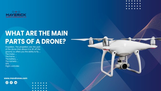
What Are The Main Parts Of A Drone?
Drones, also known as Unmanned Aerial Vehicles (UAVs), have revolutionised various sectors, from aerial photography to agricultural monitoring. Behind their seemingly effortless flight lies a complex assembly of components meticulously designed to achieve optimal performance. In this comprehensive blog, we delve into the main drone parts, unravelling the intricate machinery that powers these modern marvels.
1) Frame:
At the heart of every drone lies its frame, serving as the structural backbone upon which all other components are mounted. Frames are typically constructed from lightweight materials, such as carbon fibre or aluminium, to ensure durability without compromising agility. Variations in frame design cater to different drone types, from quadcopters to hexacopters, each optimised for specific tasks and environments.
2) Motors And Propellers:
Responsible for generating thrust and manoeuvring the drone, motors and propellers play a pivotal role in flight dynamics. Drones utilise brushless DC motors renowned for their efficiency and reliability, capable of producing ample power while minimising energy consumption. Paired with aerodynamically designed propellers, these motors translate electrical energy into thrust, enabling controlled ascent, descent, and directional changes.
3) Electronic Speed Controllers (ESCs):
Facilitating seamless communication between the flight controller and motors, Electronic Speed Controllers (ESCs) regulate motor speed and ensure precise control over the drone's movements. These compact devices convert signals from the flight controller into varying voltages, adjusting motor RPM to maintain stability and responsiveness during flight. Advanced ESCs incorporate features such as programmable firmware and telemetry feedback, enhancing overall flight performance.
4) Flight Controller:
Acting as the brain of the drone, the flight controller orchestrates its flight behaviour by processing sensor data and executing flight algorithms in real-time. Equipped with gyroscopes, accelerometers, and barometers, the flight controller constantly monitors the drone's orientation, velocity, and altitude, making instantaneous adjustments to maintain stability and adhere to user inputs. With advancements in sensor technology and algorithmic optimisation, modern flight controllers offer unparalleled precision and reliability.
5) Battery And Power Distribution System:
Powering the drone's electronics and propulsion system, the battery serves as its primary energy source, providing the necessary voltage and current to sustain flight operations. Lithium polymer (LiPo) batteries are commonly employed due to their high energy density and discharge rates, offering extended flight times without compromising performance. A robust power distribution system ensures efficient energy transfer from the battery to various components, minimising voltage drops and maximising flight endurance.
6) Remote Control Transmitter And Receiver:
Enabling wireless communication between the operator and the drone, the remote control transmitter and receiver form an essential link in the control chain. Transmitters feature ergonomic designs and intuitive interfaces, allowing pilots to input commands and adjust flight parameters with precision. Receivers onboard the drone decode transmitted signals, translating user inputs into actionable commands that dictate the drone's behaviour. Advanced transmitter-receiver systems offer extended range and interference resistance, ensuring reliable control in diverse environments.
7) Onboard Sensors:
Equipped with an array of sensors, drones gather real-time data to navigate their surroundings and maintain situational awareness during flight. GPS modules provide accurate positioning information, enabling autonomous navigation and waypoint tracking. Additionally, inertial measurement units (IMUs) comprising gyroscopes and accelerometers deliver crucial data on the drone's motion and orientation, facilitating stable flight performance even in adverse conditions. Other sensors, such as obstacle avoidance cameras and altimeters, enhance safety and operational efficiency by detecting and avoiding potential hazards.
8) Camera And Gimbal System:
For drones used in aerial photography and videography, integrated camera and gimbal systems capture stunning imagery with unparalleled clarity and stability. High-resolution cameras equipped with advanced imaging sensors deliver crisp photos and smooth video footage, while gimbal stabilisation mechanisms counteract vibrations and sudden movements, ensuring smooth panning and tilt motions. Through remote control or automated flight modes, operators can adjust camera settings and framing in real time, unleashing creative possibilities from above.
Conclusion
The evolution of drone technology has unlocked limitless possibilities across various industries, from aerial mapping and infrastructure inspection to search and rescue operations. Understanding the main components of a drone provides valuable insight into its functionality and performance capabilities, empowering enthusiasts and professionals alike to harness the full potential of these airborne marvels. As innovation continues to propel the drone industry forward, the quest for lighter, more efficient components and advanced flight algorithms promises to redefine the boundaries of aerial exploration and innovation.
0 notes
Text
KSP Weekly: A Jovian Pioneer

Welcome to KSP Weekly everyone. Today marks the 46th anniversary of the launch of Pioneer 10, the very first probe to complete a mission to Jupiter. It was launched in 1972 by an Atlas-Centaur expendable vehicle from Cape Canaveral, Florida, and weighing 258 kilograms. Thereafter, Pioneer 10 became the first artificial object to achieve the escape velocity that will allow it to leave the Solar System; only five crafts including Pioneer 11, Voyager 1 & 2, and New Horizons have achieved that. The project was conducted by the NASA Ames Research Center in California, and the space probe was manufactured by TRW Inc.
Pioneer 10 was assembled around a hexagonal bus with a 2.74-meter diameter parabolic dish high-gain antenna, and the spacecraft was spin stabilized around the axis of the antenna. Its electric power was supplied by four radioisotope thermoelectric generators that provided a combined 155 watts at launch. It also carries various scientific instruments, such as a Helium Vector Magnetometer, a Quadrispherical Plasma Analyzer, a Charged Particle Instrument (CPI), a Cosmic Ray Telescope (CRT), a Geiger Tube Telescope (GTT), a Trapped Radiation Detector (TRD), Meteoroid Detectors, an Asteroid/Meteoroid Detector (AMD), a Ultraviolet Photometer, an Imaging Photopolarimeter (IPP), and an Infrared Radiometer.
Between July 15, 1972, and February 15, 1973, it became the first spacecraft to traverse the asteroid belt. It began photographing Jupiter on November 6, 1973, at a range of 25,000,000 km, and a total of about 500 images were transmitted.
The closest approach to the planet was on December 4, 1973, at a range of 132,252 km. During the mission, the on-board instruments were used to study the asteroid belt, the environment around Jupiter, the solar wind, cosmic rays, and eventually the far reaches of the Solar System and heliosphere, which is is the bubble-like region of space dominated by the Sun, which extends far beyond the orbit of Pluto.
Radio communications were lost with Pioneer 10 on January 23, 2003, because of the loss of electric power for its radio transmitter, with the probe at a distance of 12 billion km (80 AU) from Earth.
Some scientists predict that Pioneer 10 is currently around 114.07 AU from the Earth; and traveling at 12.04 km/s relative to the Sun and traveling outward at about 2.54 AU per year. If left undisturbed, the probe and its sister craft Pioneer 11 will join the two Voyager spacecrafts and the New Horizons spacecraft in leaving the Solar System to wander the interstellar medium. The Pioneer 10 trajectory is expected to take it in the general direction of the star Aldebaran, currently located at a distance of about 68 light years. If Aldebaran had zero relative velocity, it would require more than two million years for the spacecraft to reach it.
At the behest of Carl Sagan, Pioneer 10 and Pioneer 11 carry a 152 by 229 mm gold-anodized aluminum plaque in case either spacecraft is ever found by intelligent life-forms from another planetary system. The plaques feature the nude figures of a human male and female along with several symbols that are designed to provide information about the origin of the spacecraft. The plaque is attached to the antenna support struts to provide some shielding from interstellar dust. I wonder if Kerbals will perform a similar mission to explore Jool and the outskirts of the Kerbollean Star System?
[Development news start here]
Another great week full of developments! For starters, last week we released our first patch for KSP Enhanced Edition and we haven’t lost a minute to start comping all the feedback that our beloved players are providing us with. We want once more to reiterate our commitment to continue supporting Enhanced Edition. Click here to read the detailed release notes.
Additionally, we also published a new tutorial for the upcoming Making History Expansion, where we detail the steps needed to share missions with other players. With this guide you’ll be ready to export, share and play missions from day one! Coupled with the last week’s tutorial, where we look into the process of creating missions, you’ll have the necessary tools to become a true Mission Designer on March 13th!
As expected, the developers have been very busy this week, making the final preparations for the Expansion and ongoing an exhaustive bughunt. It is common at this stage of the development process to encounter issues that managed to escape the view of the developers when things were originally implemented. Luckily, the expert eyes of our testers are working to ensure a smooth release. Kudos to all of them!
While the bug fixing is currently the main task at hand, some of the devs finished implementing the mesh switching button for the new vintage space suit. We have basically added a cycle button in the select crew window between the Kerbal icon and name. Clicking this hanger-shaped icon will change the assigned suit, and change the Kerbal icon to show the assigned suit. But an image is worth a thousand words, so check it out yourselves.

The team also added an "Author" field to the Mission Briefing tab, so that creators are properly credited for their missions.

Additionally, the team finished with the implementation of the intermediate Tutorial, which will teach players to provide missions with scores, create situational events, among other cool stuff! We are also updating some older engine audio. The task is almost done and we are currently testing that everything works (or sounds) as it should.
That’s it for this week. Be sure to join us on our official forums, and don’t forget to follow us on Twitter and Facebook. Stay tuned for more exciting and upcoming news and development updates!
Happy launchings!
[Click here for high-res images]
*Information Source:
(n.d.). Encounter with the Giant. Retrieved from https://history.nasa.gov/SP-349/ch8.htm
(n.d.). The Pioneer Jupiter Mission. Retrieved from https://history.nasa.gov/SP-349/ch2.htm
Dunbar, B. (n.d.). Pioneer-10 and Pioneer-11. Retrieved from https://www.nasa.gov/centers/ames/missions/archive/pioneer10-11.html
8 notes
·
View notes
Text
Weekly Blog 3
Research and Inspirations
As I continued coding for this project, I began researching processes and plugins for using the Leap Motion with Unity. After finally locating a plugin from the actual Leap Motion company’s development website, I ultimately decided this method wasn’t going to work, as I wasn’t able to find a neat solution for unpacking the data I needed from it (specifically position data of fingertips and position data of wrist bone). Therefore, rather than this, I redirected my research into finding a solution for getting Unity and Max MSP to communicate with one another. Having worked with the Leap Motion in Max extensively, I knew if I were able to transfer the data between the two programs I could easily do the computation needed to get the appropriate angles I need to use for Mauk.
This actually turned out to be a little harder than I expected. After some research in Unity, I located the free assets package “extOSC.” I know that Max is natively able to transmit OSC data via an object called “udpsend,” so this seemed like a great step forward! Unfortunately, after I got the assets package running I was able to accept the data, but didn’t have the technical understanding of the code necessary to turn it into the object rotation script I needed.
Having returned to researching, I was finally able to locate a package online that was specific not only for communication between Max and Unity, but included a transform function as well! After browsing the function and with some external help from my sister - a Unity expert - we were able to get the program working so that it was turning the data it received into a rotation, not a simple translation. Hooray! This serves as a great step forward, and from here I hopefully will be able to integrate the Leap Motion very soon.
Progress and Process
As I detailed above, a majority of the process and progress this week was researching various solutions for integrating the Leap Motion with Unity in the specific way that I need. However, as well as research, I also have now created the Max patch that calculates specifically the angles I need for pitch and roll of the hand.

The code on the left is the OSC transmitter from which Unity receives (currently that sends data from that square at the top). The code on the right is all of the arithmetic to calculate pitch and roll. I discovered that Max actually seems to natively work in radians and also added mathematical functions to translate the resulting radians to degrees. The next step will be a simple matter of having the transmitter send the data from my calculations rather than the data from the square, and hopefully will be little more than a matter of plugging those final message boxes into the “join 2″ function.
Reflection
Honestly, some aspects of this last week have been a bit frustrating. It was fairly exhausting to have done so much work to get the Leap Motion Unity plug in working only to find it wouldn’t give me the data I needed. I assumed (erroneously) that the plugin would be a little friendlier about letting developers get numerical data of hand positions the same way the Max Leap Motion plugin I have does, and it was disappointing to have worked so hard only to ultimately have to scrap it all.
I was disappointed the extOSC asset package ultimately didn’t work either, honestly. It was a really incredible asset package, and if I was a better programmer I probably could have found a way to make it work. I even went so far as to reach out to the developer, and he was kind enough to write me back with amazing promptness. He had never used it to communicate between Max and Unity, however, and despite his best efforts my own technical limitations ultimately forced me to abandon this package.
However, despite these disappointments, I have to say it might have made the final victory of seeing the data transmission work at the end of all this even sweeter. It reinvigorated me enough that I was able to push out the Max coding in a matter of a little over an hour. It’s left me excited for the next step, and ready and eager to stride into it.
Feedback
The only feedback I received this week would be from my sister, when she was helping me get the OSC transmission and reception to work. She told me some fairly useful advice that I intend to take with me into the future of this project - I’m significantly better at programming in Max than I am in Unity. This is why I elected to do the angle calculations in Max rather than in Unity, and it’s left me wondering if I should handle the velocity calculations here as well. It’s something I’ll have to think I little more on and tinker with, but I think it’s a viable possibility that I handle the physics calculations in Max as well and simply have Unity plug them in where they’re needed.
0 notes
Text
Military Radar Market By Type (Ground Based,Naval,Airborne and Space Based), Industry Trends, Estimation & Forecast, 2016 - 2024
Military Radar market was valued at $10.85 million in 2016 and is projected to reach $14.09 billion by 2024, having a CAGR of 3.4 % during the forecast period of 2017 to 2024.the airborne radar segment generated the highest revenue share in the global military radar market.
Radio detection and ranging also called as (RADAR) is a detection and surveillance system which uses radio waves to detect objects. It is a detection system that is used to determine the range, angle, and velocity of objects. RADAR can be used to detect aircraft, ships, spacecraft, guided missiles, motor vehicles, weather formations, and other entities. A radar system consists of a transmitter which produces radio waves, a transmitting antenna, a receiving antenna, and a receiver and processor to determine properties of the object which is being detected. Radio waves from the transmitter reflect off the object and return to the receiver, giving the exact information about the object's location and speed. Radar systems are capable enough to find any stationary or moving object and determine their shape, distance, angle, velocity and other static and dynamic properties. Radars are fundamentally developed for military applications and are majorly used for surveillance and detection. Today, military radar systems can observe objects while based on the ground, ships and aircraft carriers, aircraft, and space stations. The intense growth of advanced electronics has amplified the capacity of radar systems, expanding its application area to air and terrestrial traffic control, radar astronomy, air-defense systems, antimissile systems, aircraft anti-collision systems, ocean surveillance system and outer space.
Request Sample Copy of the Report@https://www.esticastresearch.com/market-reports/military-radar-market/request-sample
Market Dynamics
Rapidly increasing security concerns and increasing defense budgets are stimulating the industry growth prospects. Enhancement in radar technology and increased focus on the border protection activities are some factors which are extensively driving the military radar industry. The rise in terrorism activities and inter-country conflicts are some factors which would lead the industry to witness immense growth.
However, the military radar market can get badly affected by the existing economic conditions. The outcomes of the economic slowdown can also inhibit the global military spending, driving down the industry growth opportunities. The countries, such as the UK, Germany, and Russia, have witnessed cuts in defense budgets owing to financial crises. Moreover, the high costs of military radars and the capital required for the research and development of space-based radar system might act as a restraining factor for the Military Radar Market. Opportunities such as the development of lightweight radars and use of an improvised electronic system in military radar systems can help the market to grow in the near future.
Market Segmentation
The Military Radar Market is segmented by type and geography. On the basis of type, the market is categorized as Ground Based, Naval, Airborne, and Space based. By Geography, the market is segmented as North America, Europe, Asia-Pacific and Rest of World.
Some of the key market players are Lockheed Martin Corporation, Northrop Grumman Corporation, Raytheon Company, Saab Group, Thales Group, Airbus Group, BAE Systems, General Dynamics, Israel Aerospace Industries Ltd, Finmeccanica SPA.
Global Military Radar Market Segmentation
By Type:
Ground Based
Naval
Airborne
Space Based
By Geography
Request for Customized Report @https://www.esticastresearch.com/market-reports/military-radar-market/request-customise-form
North America
USA
Others
Europe
U.K
Russia
France
Italy
Germany
Other
Asia-Pacific
China
India
Australia
Japan
South Korea
Others
Rest of World
Israel
South Africa
Other
Key Market Players
Lockheed Martin Corporation
Northrop Grumman Corporation
Raytheon Company
Saab Group
Thales Group
Airbus Group
BAE Systems
General Dynamics
Israel Aerospace Industries Ltd
Finmeccanica SPA
CHAPTER 1. INTRODUCTION
1.1. RESEARCH METHODOLOGY 1.1.1. ERC desk research 1.1.2. ERC data synthesis 1.1.3. Data validation and market feedback 1.1.4. ERC data sources 1.2. RESEARCH SCOPE
CHAPTER 2. MARKET OVERVIEW
2.1. RESEARCH SUMMARY 2.2. VALUE CHAIN ANALYSIS 2.3. FIVE FORCES ANALYSIS 2.4. MARKET PLAYER POSITIONING 2.5. DEMAND FORECAST 2.6. BUSINESS INTELLIGENCE & STRATEGIC ANALYSIS 2.7. MARKET DETERMINANTS
2.7.1. Drivers 2.7.1.1. Increasing demand of radar in militaries 2.7.1.2. Territorial clashes in APAC and Middle East region 2.7.2. Restraints 2.7.2.1. Increasing cyber warfare 2.7.2.2. High cost of space-based radars 2.7.3. Opportunities 2.7.3.1. Rising demand for air missiles by defense sector 2.7.3.2. Increasing role of unmanned combat system for battlefield surveillance
CHAPTER 3. GLOBAL MILITARY RADAR MARKET BY TYPE 3.1. SEGMENT OUTLINE 3.2. GLOBAL MILITARY RADAR MARKET REVENUE BY TYPE, 2016-2024 3.3. GROUND BASED 3.3.1. Current trends 3.3.2. Market growth indicators 3.3.3. Global ground based military radar market revenue by region, 2016-2024 3.4. NAVAL 3.4.1. Current trends 3.4.2. Market growth indicators 3.4.3. Global naval military radar market revenue by region, 2016-2024 3.5. AIRBORNE 3.5.1. Current trends 3.5.2. Market growth indicators 3.5.3. Global airborne military radar market revenue by region, 2016-2024 3.6. SPACE BASED 3.6.1. Current trends 3.6.2. Market growth indicators 3.6.3. Global space based military radar market revenue by region, 2016-2024
CHAPTER 4. GLOBAL MILITARY RADAR MARKET BY GEOGRAPHY 4.1. SEGMENT OUTLINE 4.2. GLOBAL MILITARY RADAR MARKET REVENUE BY GEOGRAPHY, 2016-2024 4.3. NORTH AMERICA 4.3.1. Market trends 4.3.2. Market growth indicators 4.3.3. North America military radar market revenue by type, 2016-2024 ($Billion) 4.3.4. North America military radar market revenue by country, 2016-2024 ($Billion) 4.4. EUROPE 4.4.1. Market trends 4.4.2. Market growth indicators 4.4.3. Europe military radar market revenue by type, 2016-2024 ($Billion) 4.4.4. Europe military radar market revenue by country, 2016-2024 4.5. ASIA PACIFIC 4.5.1. Market trends 4.5.2. Market growth indicators 4.5.3. APAC military radar market revenue by type, 2016-2024 4.5.4. APAC military radar market revenue by country, 2016-2024 4.6. REST OF THE WORLD 4.6.1. Market trends 4.6.2. Market growth indicators 4.6.3. ROW military radar market revenue by type, 2016-2024 4.6.4. ROW military radar market revenue by country, 2016-2024
Access Report Details @https://www.esticastresearch.com/market-reports/military-radar-market
About Esticast Research &Consulting :
Esticast Research & Consulting is a research firm providing research reports on various industries with a unique combination of authenticity, extensive research, and infallibility. We provide syndicated market research reports, customization services, and consulting services to help businesses across the world in achieving their goals and overcoming complex challenges. We specialize in providing 360 degree view of the markets to assist clients in determining new opportunities and develop business strategies for the future with data and statistics on changing market dynamics.
Esticast Research & Consulting has expert analysts and consultants with an ability to work in collaboration with clients to meet their business needs and give opportunities to thrive in a competitive world. A comprehensive analysis of industries ranging from healthcare to consumer goods and ICT to BFSI is provided by covering hundreds of industry segments. The research reports offering market forecasts, market entry strategies, and customer intelligence will help clients across the world in harnessing maximum value on their investment and realize their optimum potential.
Contact
Esticast Research & Consulting
410 State Route 57 East,#206, Washington, NJ 07882
Tel: 1-908-379-7709
Fax: 1-908-379-7709
Email: [email protected]
0 notes
Text
The Operational Principle of Water Flow Sensor
I. The operational principle of water flow sensor—A brief introduction
Water flow sensor is a kind of instruments used for testing flow parameters of media like liquid and gas and to change them into other forms of signals for output. Water flow sensor has advantages of small size、light weight、audio—visual and clear reading、high reliability and zero pressure loss. As a result, it has been widely used in many areas such as environmental monitoring、safety protection、health care and trade settlement. However, it can not measure the flow that is non—conductive medium, which limits its development in a sense.
II. The operational principle of water flow sensor—Classification
Water flow sensor can be divided as water flow sensor、plug—in water flow sensor 、vane—typed air-water flow sensor、vortex water flow sensor、Karmen—vortex air-water flow sensor and hot—wire air-water flow sensor, etc., among which water flow sensor is mainly composed of copper valve body、flow rotor assembly、steady flow component and hall sensor. It is primarily installed on the place that intakes water to measure flooding velocity. When the water goes through the rotor assembly, magnetic rotor rotates as the speed has lineal change along with the flow. The hall sensor of this product sends the pulsing signal to give a feedback to the controller which will judge the flow whether it is big or small and adjust and control the current of proportion valve. Furthermore, the proportion valve will control the gas consumption to avoid the gas water heater appearing the phenomenon that the water becomes hot in summer while cold in winter.
III. The operational principle of water flow sensor
As what has been mentioned above, water flow sensor has many different kinds of forms, and different
water flow sensor
have varies of operational principles. For example, some of the ultrasonic flow sensors are based on Doppler method which takes advantage of reflection frequency changes when medium meets with sound waves and to produce frequency difference between sonic wave and received sound in the process of relative motion. Some will on the basis of running time method that acoustic velocity superposes flow rate. If the direction of ultrasonic is the same as flow’s, the running time is short, and vice versa. The flow rate can be calculated by the range of running time. Vortex water flow sensor is on account of vortex frequency method( vortex principle ) to set the resistivity body in the flow to shape the Karmen vortex. Under a certain circumstance, it stops both sides of the liquid from becoming a regular vortex. Differential pressure method is based on Bernoulli’s principle. What it means is that the cross section of the pipe is narrow enough to become nozzle. Because any position in pipe network has an identical flow that it is to be drop pressure. According to Bernoulli’s principle, the flow can be worked out.
We are China industrial flow meters supplier. As we all know flow meter is a kind of device to measure the amount of medium pass through the
flow sensor
, according to the medium, we can classify we supplied flow meters into liquid flow meter, gas flow meter and steam flow meters.
Flow sensors (flow transducer) and flow transmitters are the primary devices of the flow meters. Flow transducer senses the medium pass through the flow meter sensor and flow transmitter generates a kind of stable flow signal from the raw flow transducer signals. Some customers need analog flow meter which produces 4-20mA signals, or pulse flow meter, flow meter manufacturers can meet the customers’ technical specifications, and most of the flow instruments we supplied is totalizing flow meter which can not only display instant flow but also totalized flow.
We are especially good at selection of flow meter types. One specific flow meter cannot meet all the applications; custom flow meters are manufactured according to different industrial applications. We generally sort flow meters as below based on the technique of measurements.Volumetric flow meters
Electromagnetic Meter
Vortex Flow meter
Turbine Flow meter
Positive Displacement Flow meter (such as oval gear flow meter)
Variable area Flow meters
Ultrasonic Flow meter
Differential Pressure Flow meter ( such as V-cone Flowmeter, Orifice Plate.,etc )
Mass Flow meters
Thermal mass Flow meter
Coriolis Mas Flow meter
If you want to buy flow meter, and need different kinds technical specifications, such as hot water meter, sanitary flow meter, cheap air flow meter sensor, we can all meet your demands, and welcome to send inquiry to us, we will choose proper type meters for your specific applications. Each flow meter is unique on for you, China flow meter is not only good price, but also great service and amazing delivery time.
0 notes
Text
Новости сайта #ENGINEERING - 工程
New Post has been published on http://engineer.city/improving-flow-control-in-pneumatic-conveying-systems/
Improving flow control in pneumatic conveying systems
Tony Brennan looks at the advantages of pneumatic conveying and how it can be maximised
Modern industrial processes are under increasing pressure to reduce costs and improve reliability and productivity.
Where these processes involve pneumatic conveying there are opportunities to improve the design and flexibility of both existing and new installations.
The most significant advantages of pneumatic or vacuum conveying over mechanical conveying include:
* Reduced maintenance due to the lack of moving parts
* Improved operational environment with no dust due to the fully enclosed design
* High flexibility of the transfer route
* The possibility to carry out physical or chemical processes during the conveying process
* The ability to convey air-sensitive materials using an inert gas, such as nitrogen, to prevent oxidation.
Optimising the transport flow
The process of transporting materials often requires the destination to change, for example when a storage container is full and the product is diverted to the next container.
The volume of air in the transport system is crucial to maintaining the product in suspension and making changes to the required volume must be matched by a suitable adjustment to the airflow in order to keep the product in suspension and avoid unnecessary wear to the pipework or degradation of the conveyed material.
The same applies to making a change to the product itself; this will also require an adjustment to the airflow to ensure the correct air velocity and product quality are maintained.
However, the way in which the air is introduced to the conveying system can have a significant effect on the system design and the power requirements to operate it.
More traditional ‘blow pot’ solutions are giving way to systems that use multiple air injection points to provide a uniform air flow throughout the system. Increased levels of computer control and monitoring allows new installations to be delivered with much lower power requirements, which form a significant proportion of the operating costs.
Improving productivity
The key to managing these power requirements, and the subsequent costs, is to implement a control system that can react to changes in the internal volume of the transport system, maintaining the optimum airflow. This approach has resulted in the industry shifting from steady state systems towards non-steady state systems.
The ability to operate a plant with product quality variation without stopping the process due to plugged pipes can greatly improve the productivity of the plant and help to reduce the operator’s total cost of ownership.
To implement such a system requires an airflow controller that can continually assess the demands of the system and provide feedback signals for the compressors. Integrating such an air flow controller with a pneumatic conveying system that has had little or no control in the past, can be challenging.
However, recent developments in data networking, connectivity and microprocessor control have been heralded as Industry 4.0 and the Internet of Things (IOT). Advances in design technology and the reduction in costs have resulted in a huge increase in the amount of technology available to measure and control industrial processes.
When applied to pneumatic conveying it enables the continuous measurement of material mass flow rates and the adjustment of air flow rates using computer algorithms to both within an optimum range. Furthermore, this data can be collected and analysed centrally to ensure that the plant continues to operate at the best efficiency.
Maximising efficiency
One possible solution for delivering improved efficiency is a closed loop controller that features a flow sensor, a process controller and a control element, all in one unit.
As such, a compact and flexible design would enable the flow controller to be installed easily and provide accurate management of the compressors.
Bürkert specialises in developing solutions for customers in a diverse range of industries, delivering flow control systems for a wide variety of applications.
The latest offering addresses the issues associated with creating a standalone control system for pneumatic conveying, all in one product.
The Type 8750 flow rate controller provides a solution that can reduce operating costs and improve productivity through better management of the compressors.
The pneumatic seat valve compensates for the air leakage across the rotary valve that introduces the solids to the conveying air stream.
The Type 8750 can store the flow leakage curve of each rotary valve so that for any given inlet pressure the 8750 knows how much additional air is required to compensate for the air lost from the system by the rotary valves.
The flow rate control system consists of an ELEMENT continuous control valve (Type 2301) with a compact process controller (Type 8693) and two pressure transmitters, (Type 8323).
These components are supplied as an assembled system that negates the requirement for a separate flow meter.
Using the pressure difference across the valve and the given density and temperature of the medium, a nominal flow can be calculated, providing the flow characteristics of the valve to the process controller. The volume flow can then be adjusted by changing the stroke of the control valve.
The control valve serves as an orifice plate to connect pipework so installation is straightforward and there is far less of a pressure drop compared to alternative arrangements.
Creating flow control systems can be a complex issue, especially if you are dealing with the pharmaceutical or the food and beverage industries.
The standards that need to be met when designing and constructing processing infrastructure can be very stringent. Bürkert has been designing and installing flow control systems for these, and many other industries, for 70 years and in this time has developed an in-depth knowledge of the requirements for success.
Tony Brennan is Field Segment Manager, Gas and Micro for Bürkert.
Tags:
low control
pneumatic conveying systems
Bürkert.
Images:
Categories:
Process Engineer
[10] Materials Handling
Source: engineerlive.com
0 notes
Text
1 note
·
View note
Text
1 note
·
View note
Text
1 note
·
View note
Text
1 note
·
View note
Text
1 note
·
View note
Text
1 note
·
View note
Text
1 note
·
View note
Text
1 note
·
View note