#atmega16a
Explore tagged Tumblr posts
Visit Tumblr Blog
Explore Tumblr blogs with no restrictions, modern design and the best experience.
Last Seen Tumblr Blogs


Fun Fact
The “We are the 99%” Tumblr blog became the slogan for the Occupy Wall Street movement.
Text
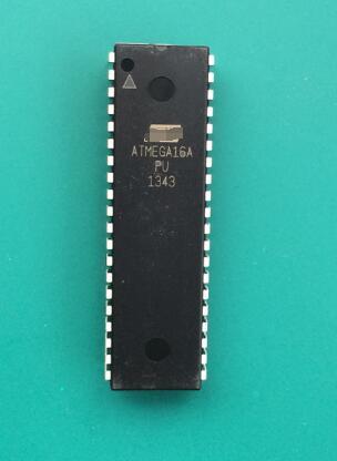
This is a DIP-40 package 8-bit Microcontroller IC with 32 Programmable I/O lines, and 16K Bytes In-System Programmable Flash.
1 note
·
View note
Text
I2C master mode emulator
I2C is a popular data bus to communicate with inter-board peripherals. Today I2C based chips and modules are widely available in many categories, including data storage, ADC/DAC, I/O Expanders, sensors, etc.

The I2C master mode emulator allows communication with I2C devices by sending or receiving data to/from the I2C bus. To issue the I2C commands, the emulator should connect to a PC over the USB port. After initializing the emulator, the PC and directly control the I2C slave chip/module.
This emulator is base on ATmega16A MCU. The USB communication channel is develop using the V-USB firmware.
Initially, we develop this emulator to work with 5V I2C devices, but later it has extended to work with 3.3V I2C devices. The 3.3V design is still under testing, and at the prototyping stage, we found a couple of issues in 3.3V mode.
In 3.3V mode, the required output level is available only if the emulator is in a "ready" state. In all the other states, it provides 5V output. Therefore in 3.3V mode, necessary precautions need to be taken to protect the slave device from over-voltage damages.

To build the prototype, we use single side home-made PCB. The dimensions of the PCB are 96.77mm × 110.73mm.
This emulator needs an external power supply, and the recommended supply voltage is between 12V - 15V.
The control software of the emulator is developed using libusb and tested only with Linux operating systems.
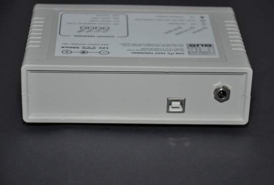
The control software source code, PCB design, schematics, firmware source code, and compiled binaries of this emulator are available at my GitHub repository. The complete documentation is also available in the wiki section of the GitHub repository.
0 notes
Photo
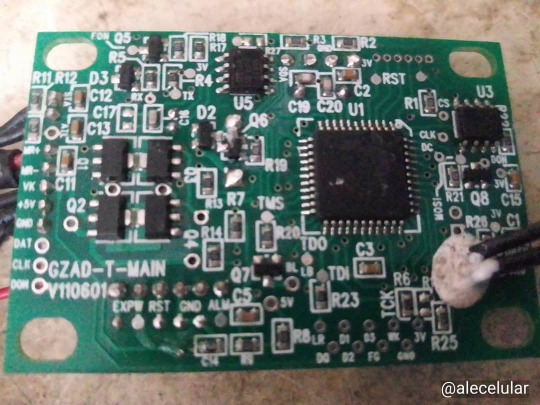
Día 501 de la cuarentena. Capítulo 749. Encontré en la calle entre destrozos de algún aparato incierto, esta plaqueta que contiene un procesador ATMEGA16A, una memoria flash de 512k y un RTC. No sé cual función cumplia, pero veré de experimentarla, ya que tiene todo para hacer pruebas. (en Constitución, Distrito Federal, Argentina) https://www.instagram.com/p/CSDFg9ulmod7lBe6Di7TM6YbDw0T_ImqaA1Dqo0/?utm_medium=tumblr
0 notes
Text
Freeshipping ATMEGA16A-PU ATMEGA16A ATMEGA16
Freeshipping ATMEGA16A-PU ATMEGA16A ATMEGA16
lastest_volume
0
Just For Today
Click Here To Visit The Shop
N€W Freeshipping ATMEGA16A-PU ATMEGA16A ATMEGA16
0 notes
Text
Exploit IT Solutions Hiring Embedded Engineer
Exploit IT Solutions Hiring Embedded Engineer
Job ID : 20180714012
Company : Exploit IT Solutions Pvt Ltd
Job Role : Embedded Software Engineer
Eligibility : Graduate
Experience : Experienced
Job Location : Hyderabad
Salary : 15000-22000/Month
Vacancies : Not Mentioned
Website : http://www.exploitinfo.com
Description :
Good knowledge on c embedded cHandson experience on different controllers atmega16A Atmega328p AT89S51
Good Working…
View On WordPress
0 notes
Text
New Post has been published on Detectorzine.com
New Post has been published on http://detectorzine.com/product/wingoneer-atmega16a-usb-avr-jtag-emulator-programmer-debugger-for-avr-atmega/
WINGONEER ATMEGA16A USB AVR JTAG Emulator Programmer Debugger For AVR ATMega
WINGONEER® trademark Reg.NO:4747611
WINGONEER ATMEGA16A USB AVR JTAG Emulator Programmer Debugger For AVR ATMega
Features: Complete on-chip JTAG-based debug tools, supports all AVR 8-bit RISC instruction with a JTAG port of the microprocessor. 4-wire JTAG interface is a standards-compliant IEEE 1149.1 test access port (TAP) controller. IEEE standards board to provide an effective test of the standard method of connectivity (Boundary Scan). AVR devices has been extended to support full programming and on-chip debugging functions. Increase the buffer chip (Prevent to damage the firmware for improper operation); Increase the resettable fuse (to prevent short circuit burned out the computer motherboard); AVR JTAG interface to Support AVR Series MCU which have AVR JTAG interface. Enable single-step, continuous, breakpoints, variable data or program space with a breakpoint. Can Flash, EEPROM, Fuse, encryption, digital programming.
Supported chips: ATMega16, ATmega16L, ATMega162, ATmega162V, ATmega165, ATmega165V, ATMega169, ATmega169V, ATMega32, ATMega323, ATmega323L, ATmega32L, ATMega64, ATmega64L, ATMega128, ATmega128L, AT90CAN128
Package included: 1x WINGONEER ATMEGA16A USB AVR JTAG Emulator Programmer Debugger For AVR ATMega
Features
Main chip: ATMEGA16A
Support AVR Studio 4.18
4-wire JTAG interface is a standards-compliant IEEE 1149.1 test access port (TAP) controller
AVR devices has been extended to support full programming and on-chip debugging functions.
AVR JTAG interface to Support AVR Series MCU which have AVR JTAG interface. Enable single-step, continuous, breakpoints, variable data or program space with a breakpoint.
0 notes
Text
FM stereo radio receiver with RDS
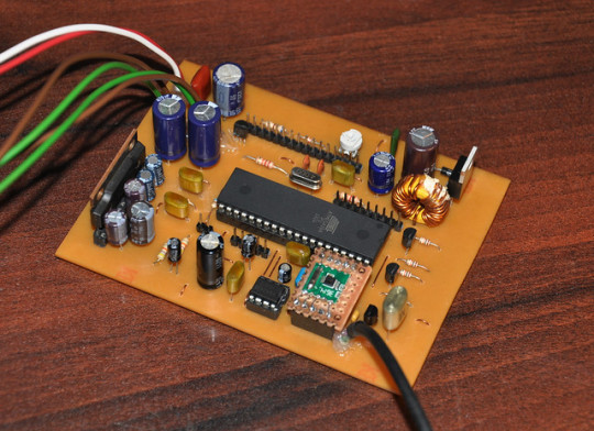
This tuner circuit is a quick prototype which I build to test the RDA5807M FM radio tuner IC. RDA5807M is a single-chip tuner IC with RDS and MPX decoder, and it equipped with I2C interface for control. The main reason to build this prototype is to understand the behavior of this chip.
At the time of this design, the website of the RDA microelectronics is not accessible from my location. Because of this reason, I download different versions of RDA5807M datasheets from the internet. While going-through those datasheets, I observed that it comes with limited information. Finally, I decided to build this receiver to verify some of those parameters and to review the RDS functionality of the chip.
I build this receiver around ATmega16A MCU. I choose this MCU because I got a few of ATmega16A MCUs in my inventory and also due to the higher number of I/O pin count.
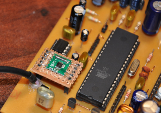
In this design, the volume is controlled using M62429 IC. For the output stage, I used AN7147N, 2×5.3W audio power amplifier IC.
Based on the specifications of the switching-regulator and power amplifier, this circuit can drive between 9V to 20V DC input. At prototyping stages, we power this circuit using a 12V - 2.5A power supply unit.
The main problem which I encounter with this project is its PCB design. At prototyping stages, I did a couple of PCB designs to avoid interference and distortions. It seems like RDA5807M and AN7147N are sensitive to noise and need a proper PCB layout. In this final design, I got excellent results, and it performs better than I expected.
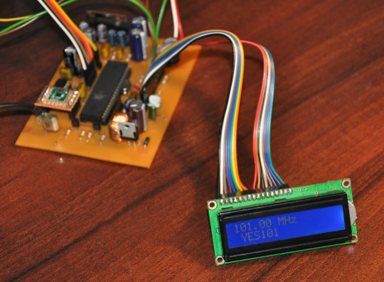
At the testing stages, this receiver decodes RDS signals from all the FM station including weak stations. "RanOne FM" is the most attractive station name which I captured from this receiver. This station transmits its name in an animated style and its display on the receiver's LCD without any problems.
The firmware of this receiver is developed using two verification buffers to avoid RDS decode errors. This technique helps to filter garbage data received due to poor reception.
The current version of the firmware supports both manual and auto-tuning functionalities with 100kHz spacing and, it is set to operate within 87MHz to 108MHz range.
The circuit diagram, PCB designs and firmware source code of this receiver are available at github.com.
0 notes
Text
High-priced recycling MICROCHIP chips, full series and full models, long-term online procurement of factory inventory IC chips, company's personal project surplus chips, integrity and formality, high professional price ATMEGA328P-AU
ATMEGA2560-16AU
PIC18F4620-I/PT
PIC32MX575F512L-80I/PT
ATMEGA644PA-AU
MCP23S17-E/SS
KSZ9031RNXIC
ATMEGA128A-AU
PIC18F46K22-I/PT
ATMEGA8A-AU
25LC512-I/SN
PIC16F1938-I/SS
PIC18F8722-I/PT
ATMEGA64A-AU
ATMEGA328P-PU
ATMEGA32A-AU
DSPIC33EP512MU810-I/PT
ATMEGA16A-AU
PIC18F4685-I/PT
PIC32MX795F512L-80I/PT
PIC18F45K22-I/PT
PIC16F1939-I/PT
PIC32MX795F512L-80I/PF
DSPIC30F5011-30I/PT
PIC18F46K80-I/PT
MCP23017-E/SS
24LC64T-I/SN
ENC28J60-I/SS
ATMEGA88PA-AU
ATMEGA1284P-AU
ATMEGA168PA-AU
ATMEGA8L-8AU
AT90CAN128-16AU
ATMEGA328P-MU
PIC16F887-I/PT
MCP4728-E/UN
PIC18F25K22-I/SS
PIC18F4680-I/PT
PIC12F675-I/SN ATMEGA328PB-AU PIC16F1823-I/SL 24LC256T-I/SN AT24C02C-SSHM-T
PIC18F25K22-I/SO ATXMEGA128A1-AU
PIC18F4520-I/PT ATXMEGA128A1U-AU ATMEGA8515-16AU MCP2515-I/SO MCP1702T-3302E/CB
24LC16BT-I/SN AT89C51RD2-SLSUM
LAN8720AI-CP-TR AT24C64D-SSHM-T
MCP23S17-E/SO KSZ8863RLLI ATMEGA2561-16AU AT24C256C-SSHL-T LAN8720A-CP-TR KSZ8863RLL ATMEGA48PA-AU DSPIC33FJ256MC710A-I/PT KSZ8895MQXIA ATMEGA32U4-AU PIC16F1937-I/PT MCP23017-E/SO PIC16LF1829-I/SO PIC18F6722-I/PT 24LC256-I/SN PIC18F67K22-I/PT ATMEGA128-16AU 24LC64-I/SN PIC16F1829-I/SS MCP4728T-E/UN ATMEGA644P-20AU ATXMEGA128A4U-AU MCP4725A0T-E/CH
PIC18F66K80-I/PT MCP6002T-I/SN
MCP7940N-I/SN PIC18F26K22-I/SS ATXMEGA256A3-AU PIC18F2420-I/SO ATMEGA32U4-MU 25LC1024-I/SM KSZ8995MAI USB2514BI-AEZG ATXMEGA32A4U-AU PIC12F1822-I/SN ATSAM3X8EA-AU PIC18F6520-I/PT PIC16F676-I/SL MCP2515-I/ST PIC18F2520-I/SO AT24C512C-SSHD-T AT25256B-SSHL-T AT91SAM7S256D-AU PIC16F688-I/SL
MIC2026-1YM KSZ8863MLL
0 notes