#delaytimer
Explore tagged Tumblr posts
Visit Tumblr Blog
Explore Tumblr blogs with no restrictions, modern design and the best experience.
Last Seen Tumblr Blogs


Fun Fact
Tumblr has been providing a Korean-language service since 2013.
Text
Understanding Serial Peripheral Interface Communication Protocol
In this article we will learn in depth about the Serial Peripheral interface which is among the widely used communication protocol in Embedded and IOT world.
What is Serial Peripheral Interface - SPI?
SPI is a synchronous serial communication protocol that enables communication between microcontrollers, sensors, memory devices, and other peripheral devices. It allows for full-duplex communication, meaning data can be sent and received simultaneously.
Serial Peripheral Interface (SPI) offers advantages such as high-speed data transfer, simplicity, and versatility.
The serial peripheral interface (SPI) is a communication interaction protocol used to send data between multiple IoT Devices. The Serial Peripheral Interface (SPI) offers data exchange among multiple devices through a master-slave configuration. In SPI the master device begins communication, by sending action bits to the slave devices. In SPI protocol one device serves as the master, with the rest acting as slaves. These modules operate synchronously and SPI ensures simultaneous transmission and reception of data at high speeds. SPI proves efficient for inter-device communication, offering higher data transfer rates compared to alternative interfaces. Its ability to handle bidirectional data flow concurrently enhances efficiency. However, SPI requires more signal lines compared to alternative protocols.
Sample ESP32 code to integrate BME280 (Pressure, Temperature, Humidity) SPI Sensor using Adafruit_BME280 library:
/*
Rui Santos
Complete project details at https://RandomNerdTutorials.com/esp32-spi-communication-arduino/
Based on the Adafruit_BME280_Library example: https://github.com/adafruit/Adafruit_BME280_Library/blob/master/examples/bme280test/bme280test.ino
Permission is hereby granted, free of charge, to any person obtaining a copy
of this software and associated documentation files.
The above copyright notice and this permission notice shall be included in all
copies or substantial portions of the Software.
*/
#include <Wire.h>
#include <Adafruit_Sensor.h>
#include <Adafruit_BME280.h>
#include <SPI.h>
#define BME_SCK 25
#define BME_MISO 32
#define BME_MOSI 26
#define BME_CS 33
#define SEALEVELPRESSURE_HPA (1013.25)
//Adafruit_BME280 bme; // I2C
//Adafruit_BME280 bme(BME_CS); // hardware SPI
Adafruit_BME280 bme(BME_CS, BME_MOSI, BME_MISO, BME_SCK); // software SPI
unsigned long delayTime;
void setup() {
Serial.begin(9600);
Serial.println(F("BME280 test"));
bool status;
// default settings
// (you can also pass in a Wire library object like &Wire2)
status = bme.begin();
if (!status) {
Serial.println("Could not find a valid BME280 sensor, check wiring!");
while (1);
}
Serial.println("-- Default Test --");
delayTime = 1000;
Serial.println();
}
void loop() {
printValues();
delay(delayTime);
}
void printValues() {
Serial.print("Temperature = ");
Serial.print(bme.readTemperature());
Serial.println(" *C");
// Convert temperature to Fahrenheit
/*Serial.print("Temperature = ");
Serial.print(1.8 * bme.readTemperature() + 32);
Serial.println(" *F");*/
Serial.print("Pressure = ");
Serial.print(bme.readPressure() / 100.0F);
Serial.println(" hPa");
Serial.print("Approx. Altitude = ");
Serial.print(bme.readAltitude(SEALEVELPRESSURE_HPA));
Serial.println(" m");
Serial.print("Humidity = ");
Serial.print(bme.readHumidity());
Serial.println(" %");
Serial.println();
}
Key Features of SPI
Full-Duplex Communication: SPI allows simultaneous data transmission and reception between the master and slave devices.
Master-Slave Architecture: One master device controls the communication and initiates data transfer to one or more slave devices.
Synchronous Communication: Data transfer in SPI is synchronized with a clock signal generated by the master device.
Variable Data Frame Format: SPI supports variable data frame formats, allowing flexibility in data transmission.
High-Speed Communication: SPI operates at high speeds, making it suitable for applications requiring rapid data transfer.
Advantages
No need for start and stop bits, providing continuous streaming of data without interruptions.
Higher data transfer rates compared to I2C (almost twice as fast).
Absence of a complex slave addressing system, unlike I2C.
Dedicated MISO and MOSI lines enabling simultaneous data transmission and reception.
Disadvantages
Requires four wires for communication which increase the circuit size
Lacks acknowledgment of successful data reception (unlike I2C).
Absence of error-checking mechanisms such as parity bit in UART.
Applications of SPI
Interfacing with sensors such as accelerometers, gyroscopes, and temperature sensors.
Memory devices like EEPROMs, flash memory, and SD cards.
Communication between microcontrollers and peripheral devices.
Display interfaces in TFT LCD displays and OLED displays.
Networking peripherals such as Ethernet controllers and Wi-Fi modules.
Conclusion
Serial Peripheral Interface (SPI) is a versatile communication protocol widely used in embedded systems and IOT applications for its simplicity, high-speed data transfer, and flexibility. Understanding the fundamentals of SPI, its protocol sequence, applications, and best practices for implementation is essential for engineers and developers working on embedded systems projects. By mastering SPI communication, you can efficiently interface with a wide range of peripheral devices like displays, sensors, modules, microcontrollers and unleash the full potential of your embedded systems designs.
If you’re an Embedded Developer and looking to implement SPI protocol in your project then Campus Component is there for you to assist you integrating SPI successfully in your project. We are the best electronics suppliers that supply all types of SPI devices with end-to-end support. Visit Campus Component now.
0 notes
Text
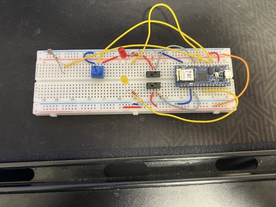
Makerspaces Week 3
We have made it through yet another 168 hours of Makerspaces! This week was full of opportunities to test yourself and grow as a creator.
This week's circuits showed me the light- both mentally and quite literally. Last week's circuit was rough but with some continued practice, this week's circuits, although more tedious, went very well. We had 2 builds this week, Circuit #3 which is the color changing LED circuit, and Circuit #4 which is the multi LED circuit. The coding for the builds revealed their actualities and what leads to their successful functions. Once the boards were constructed, coded, and tested, the next challenge was to combine the codes and run them simultaneously.
Circuit #3
Circuit 3- Color changing LED
The basis of this circuit is the LED prongs. Each one represents a primary color- red, green, and blue, with a ground prong in between (it is the longest prong)
You can make a magnitude of colors with these
The different colors come from the variation/ cycling of power supply to the specific LED prongs
Resistors are in the circuit to control how much power accesses the prongs each, making sure they are not fried
Display time see to 100 ms
I can use this to adjust the fade time- faster or slower
Cycles through 8 colors- i can make more by adjusting the power supply between the 3 pin colors in the code- HIGH, LOW
Red: R- High, G- Low, B- Low
Green: R- Low, G- High, B- Low
Blue: R- Low, G- Low, B- High
Yellow: R- High, G- High, B- Low
Etc
1000 ms delay between each See video below for circuit 3
Circuit 4- Multiple LEDs
The basis of this circuit was to explore the new concept of Arrays- holding multiple variables.
Each LED has its on pin and the pin locations are important because they have to correlate in the code
Arrays are important in coding because they represent certain variables. They start at an index of 0
In the code you have to notate the series of pins being used. I chose the code where all of the lights are turned on, and then all back off
1000ms time delay See video below for circuit 4
Compound build-
I used components from the last few circuit builds
Multiple LEDS
Color changing LED
Potentiometer
Combined code: modified the pin locations because i only used 3 LEDs for that section
Programed the color changing LED to only show main colors- put that location in the same code as the multi LEDs and used the color LED in place of 3 additional
Programmed and connected the potentiometer. I tested it with one location and modified the code to say pin 2 instead of the basic pin 13. It worked and I was able to change the speed
I tested each of the codes separately and they all work
For the combination circuit, the goal was to have a “countdown” to the color changing LED. I would also be able to control the speed with the potentiometer
I used 3 regular LEDs, 1 multicolor LED, and 1 potentiometer
I tried to combine the codes to run all of the functions at the same time but it kept receiving error messages See video below for compound build
The Codes I used for each of my programs:
Multi LED
int ledPins[] = {2,3,4,5,6,7};
void setup()
{
int index;
for(index = 0; index <= 5; index++)
{
pinMode(ledPins[index],OUTPUT);
// ledPins[index] is replaced by the value in the array.
// For example, ledPins[0] is 2
}
}
void loop()
{
void oneAfterAnotherNoLoop()
{
int delayTime = 100;
// turn all the LEDs on:
digitalWrite(ledPins[0], HIGH); //Turns on LED #0 (pin 2)
delay(delayTime); //wait delayTime milliseconds
digitalWrite(ledPins[1], HIGH); //Turns on LED #1 (pin 3)
delay(delayTime); //wait delayTime milliseconds
digitalWrite(ledPins[2], HIGH); //Turns on LED #2 (pin 4)
delay(delayTime); //wait delayTime milliseconds
digitalWrite(ledPins[3], HIGH); //Turns on LED #3 (pin 5)
delay(delayTime); //wait delayTime milliseconds
digitalWrite(ledPins[4], HIGH); //Turns on LED #4 (pin 6)
delay(delayTime); //wait delayTime milliseconds
digitalWrite(ledPins[5], HIGH); //Turns on LED #5 (pin 7)
delay(delayTime); //wait delayTime milliseconds
// turn all the LEDs off:
digitalWrite(ledPins[5], LOW); //Turn off LED #5 (pin 7)
delay(delayTime); //wait delayTime milliseconds
digitalWrite(ledPins[4], LOW); //Turn off LED #4 (pin 6)
delay(delayTime); //wait delayTime milliseconds
digitalWrite(ledPins[3], LOW); //Turn off LED #3 (pin 5)
delay(delayTime); //wait delayTime milliseconds
digitalWrite(ledPins[2], LOW); //Turn off LED #2 (pin 4)
delay(delayTime); //wait delayTime milliseconds
digitalWrite(ledPins[1], LOW); //Turn off LED #1 (pin 3)
delay(delayTime); //wait delayTime milliseconds
digitalWrite(ledPins[0], LOW); //Turn off LED #0 (pin 2)
delay(delayTime); //wait delayTime milliseconds
}
Potentiometer
int sensorPin = 0;
int ledPin = 2;
void setup() //
pinMode(ledPin, OUTPUT);
void loop(){
int sensorValue;
sensorValue = analogRead(sensorPin);
digitalWrite(ledPin, HIGH); // Turn the LED on
delay(sensorValue); // Pause for sensorValue
// milliseconds
digitalWrite(ledPin, LOW); // Turn the LED off
delay(sensorValue); // Pause for sensorValue
// milliseconds
// Remember that loop() repeats forever, so we'll do all this
// again and again.
}
Final reflection looking at what you learned through the project, the process you took to make it work or if it is not working, what the next steps would be to further debug the project.
Throughout this project, I’ve learned that you can combine multiple codes into one file, making the device have multiple functions. I also noted that just because a circuit can work electrically, does not mean it will work code wise. Also, it is very easy to create a code to run individually, but it becomes a challenge when you are trying to combine them into one code file. My next steps are to get better at coding different codes in one file. I believe I am steady enough to build the circuits quite easily. I’ve been able to sketch a vision and execute it physically, I just need to fine tune my code writing. Finally, look at the project you completed and share possible extensions of this project into where you may find examples of similar programs/circuits in the real world.
Some real work applications using some of the builds from this week include LED screens, the individual lights will light based on what the user wants the board to say and the position of the LEDs. Other examples include Christmas lights and lights inside of a home that have the dimmer capability. I would like to explore the dimming portion on the potentiometer.
0 notes
Text
#aaaaaw?????? #radioshack #wouldknow #woz #maybe #too @asus @intel @der8auer @youtube .@woz @apple @radioshack @wireduk @c alifornia @texas @wired @cnet @techpowerup @northridgefix @le arnelectronicsrepai @zorincomputers @electronicsrepairschool @p cwelt @electric @electronic itwouldnot ruin thesystem itm eans the s l o w e s t mosfets would work the h a r d e s t and t h e s e wouldbe the double robust ones itwouldbe a qua rter as fast asbefore b u t !!!!!!!!i suspect themosfets are n o t the bottleneck of switchingspeed but o t h e r components like cpu wait times clockcycles and such are thelimiting facto i f the electric part is the bottleneck its mosfet switchi ngspeeds t h e n itwouldbe a little slower than it c o u l d be simple heh? ///// N1R7 high gate capacitance 5000picofar ad vs 4c06 4c09 1200 surprise has the 4 times slower delaytimes: the gatecapacitor trait decides the reactiontime: now is 10ns or 40ns mosfet switching really thebottleneckof thesystem then
#aaaaaw?????? #radioshack #wouldknow #woz #maybe #too @asus @intel @der8auer @youtube .@woz @apple @radioshack @wireduk @california @texas @wired @cnet @techpowerup @northridgefix @learnelectronicsrepai @zorincomputers @electronicsrepairschool @pcwelt @electric @electronic itwouldnot ruin thesystem itmeans the s l o w e s t mosfets would work the h a r d e s t and t h e s e wouldbe the double…
View On WordPress
0 notes
Photo

Delay on Make Timer #delaytimer #timer #timerpics #hvac #hvacinstall #hvacrepair #hvactech #hvacr #hvachacks #hvaclove #hvacproblems #hvacwork #hvacdxb #dubai #uae🇦🇪 https://www.instagram.com/p/CGcsl33FXos/?igshid=bw33rohr8qgh
#delaytimer#timer#timerpics#hvac#hvacinstall#hvacrepair#hvactech#hvacr#hvachacks#hvaclove#hvacproblems#hvacwork#hvacdxb#dubai#uae🇦🇪
0 notes
Photo


Fender - ECHOTRONIC ECHO CHAMBER
“ ... Fender Tape Echo. Introduced in 1963, this model was used by bands like The 13th floor elevators etc!, delaytimes from 0 to 400 milliseconds “
cred: vintage-guitars.se/A4064366
58 notes
·
View notes
Photo

Mortadella . Been in Bologna without a mortadella sandwich (panino con la mortadella) is not possible so before train starting I want have dinner with 'lamortazza'. . . . #paninoconlamortadella #dinnerinbologna #frecciarossa1000 #delaytime #trainstation #sempreinritardo #aspettandolapartenza (presso Stazione Bologna Centrale) https://www.instagram.com/p/B28bkRTnJHR/?igshid=1gk525710p9ao
#paninoconlamortadella#dinnerinbologna#frecciarossa1000#delaytime#trainstation#sempreinritardo#aspettandolapartenza
0 notes
Photo


[170104] “Prelude” Comeback Showcase - Chaekyung Timedelay | do not edit
9 notes
·
View notes
Video
tumblr
PRÁCTICA CON 2 MATRIZ LED. CORAZONES PALPITANTES (Necesita biblioteca led control descargable en el siguiente enlace: https://github.com/wayoda/LedControl/releases)
#include <LedControl.h>
//Declaramos los pines: DIN, CLK, CS y el nº de displays conectados en serie LedControl lc=LedControl(8,10,9,2);
//Pausa entre frames unsigned long delayTime=900;
//Codigo de los 2 frames que vamos a mostrar: //Corazón pequeño byte Heart1[] = { B00000000, B01100110, B11111111, B11111111, B01111110, B00111100, B00011000, B00000000};
//Corazón grande byte Heart2[] = { B01100110, B11111111, B11111111, B11111111, B11111111, B01111110, B00111100, B00011000};
//Sub para transformar array #1 en un patron para la matriz void Heart1GO() { for (int i = 0; i < 8; i++) { lc.setRow(0,i,Heart1[i]); lc.setRow(1,i,Heart2[i]); } }
//Sub para transformar array #2 en un patron para la matriz void Heart2GO() { for (int i = 0; i < 8; i++) { lc.setRow(0,i,Heart2[i]); lc.setRow(1,i,Heart1[i]); } }
//Esta sub se ejecutará 1 sola vez al arrancar el Arduino void setup() { lc.shutdown(0,false); //Iniciamos la matriz led #1 lc.shutdown(1,false); //Iniciamos la matriz led #2 lc.setIntensity(0,5); //Intensidad de los led en la matriz #1 lc.setIntensity(1,5); //Intensidad de los led en la matriz #2 lc.clearDisplay(0); //Apagamos todos los led de la matriz #1 lc.clearDisplay(1); //Apagamos todos los led de la matriz #2 }
//Esta sub se ejecutara en bucle una y otra vez mientras el Arduino este alimentado. void loop() { Heart1GO(); //Mostramos el patrón #1 delay(delayTime); //Pequeña pausa Heart2GO(); //Mostramos el patrón #2 delay(delayTime); //Pequeña pausa }
2 notes
·
View notes
Text
For Project 1, I want to improve what I did for the Digital Ins and Outs assignment to make it more interactive. So I decided to add a knob and a photoresistor to control the time between switch the Leds.
In a room with sufficient lighting, the delay time between the switch of Leds will depend on the knob. However, if you block the lights for the photoresistor, the Leds will start to flash like an alarm which tells you that you need more light!
Here is my code:
// constants won't change. They're used here to set pin numbers: const int buttonPinOne = 2; // the number of the pushbutton pin const int buttonPinTwo = 20; // the number of the pushbutton pin const int ledPinOne = 5; // the number of the LED pin const int ledPinTwo = 18; // the number of the LED pin
// variables will change: int buttonStateOne = 0; // variable for reading the pushbutton status int buttonStateTwo = 0; // variable for reading the pushbutton status int delayTime = 0; int anVal = 0; int anInputPin = A1;
void setup() { // initialize the LED pin as an output: pinMode(ledPinOne, OUTPUT); // initialize the pushbutton pin as an input: pinMode(buttonPinOne, INPUT); // initialize the LED pin as an output: pinMode(ledPinTwo, OUTPUT); // initialize the pushbutton pin as an input: pinMode(buttonPinTwo, INPUT);
Serial.begin(9600); }
void loop() { int knobValue = analogRead(A0); anVal = analogRead(anInputPin);
buttonStateOne = digitalRead(buttonPinOne); buttonStateTwo = digitalRead(buttonPinTwo); if(anVal > 600){ delayTime = 100; } else{ delayTime = knobValue + 200; }
if (buttonStateOne == HIGH && buttonStateTwo == LOW) { digitalWrite(ledPinOne, HIGH); digitalWrite(ledPinTwo, LOW);} else if (buttonStateTwo == HIGH && buttonStateOne == LOW) { digitalWrite(ledPinTwo, HIGH); digitalWrite(ledPinOne, LOW);} else if(buttonStateOne == HIGH && buttonStateTwo == HIGH){ digitalWrite(ledPinTwo, HIGH); digitalWrite(ledPinOne, LOW); delay(delayTime); digitalWrite(ledPinTwo, LOW); digitalWrite(ledPinOne, HIGH); delay(delayTime);} else{ digitalWrite(ledPinOne, LOW); digitalWrite(ledPinTwo, LOW); } }
0 notes
Photo

Raptorize: A jQuery Plugin
An awesome jQuery plugin that unleashes a Raptor of Jurassic proportions... Well, technically it's Cretaceous proportions, but I'll let that slide for now.
We’ve All Been Here Before...
You're sitting at your desk, coding up a 500 page site when you realize...this page would be:

You immediately scramble home to grab your Jurassic Park DVDs so can screencap a Velociraptor attack, but then you realize how hard it would be to make an awesome raptor run across the site you were coding. Plus, how are you going to get that trademark velociraptor screech ? How about I let you in on a little secret?
I already did it.
The Raptorize Kit
First things first, you need to download the Raptorize Kit. This kit has...
An awesome Raptor Graphic
MP3 and OGG audio files for the HTML5 audio on Webkit and Firefox
Our jQuery Plugin which makes the magic happen
The jQuery Library to make all the pieces work together
An example HTML file that has all the initial setup pieces
Next, open the index.html file and click the button to activate a prehistoric beast. There you go!
The Code You Need
First let's attach the scripts and actiavte the plugin in the head of your document:
<script src="https://ajax.googleapis.com/ajax/libs/jquery/1.4.3/jquery.min.js"></script> <script>!window.jQuery && document.write('<script src="jquery-1.4.3.min.js"><\/script>')</script> <script src="jquery.raptorize.1.0.js"></script> <script type="text/javascript"> $(window).load(function() { $('.myButton').raptorize(); }); </script>
The only piece that you need to know here is that you need an anchor or element with the class 'myButton'. And there you have it, you're done!
The Options
What's that? You want to be able to control the entrance handler? You can! Raptorize can be activated on a click event (that is the default and what we have hooked up above), a timer which just fires after the page is loaded, or the legendary Konami-Code. My personal favorite is the Konami-Code (but it only works once per page load).
<!-- The options for this plugin --> <script type="text/javascript"> $(window).load(function() { $('.button').raptorize({ 'enterOn' : 'click', //timer, konami-code, click 'delayTime' : 5000 //time before raptor attacks on timer mode }); }); </script>
Go ahead, try the Konami Code (↑ ↑ ↓ ↓ ← → ← → B A)
Technical Note: If you don't want to store the Raptor image and sound files in the same directory as your javascript you need just open up the plugin and edit the location of the assets in the first 2 variables in the code (raptorImageMarkup and raptorAudioMarkup).
Credit Where Credit is Due
While the awesomeness that is the Raptorize plugin is 100% original code, the idea of including a glorious raptor into a design is not. Please owe credit to Markus Sladek for the raptor assets and the brilliance of adding a Raptor to a design. Copyright Markus Sladek, freely available for distribution under the MIT license.
Full Screen Demo
Download File
1 note
·
View note
Text
The Passive_aggressive Hat final code
The final project code. A few minor tweets to improve sensor readings and clean up code where possible.
#define HAPPY 1 #define SAD 2 #define RESTING 3 // Set-up low level interrupts for most accurate BPM maths #define USE_ARDUINO_INTERRUPTS true
#include <LedControl.h> #include <binary.h> #include <Servo.h> #include <PulseSensorPlayground.h>
Servo myServo; // The LED on the Arduino board const int LED13 = 13; // 'S' signal pin connected to A0 const int PulseWire = 0; // signal pin connected to A2 const int GSR = A2; // Determine which Signal to "count as a beat" and which to ignore int Threshold = 500;
// Servo position int pos = 0; // GSR sensor values int sensorValue = 0; int gsrAverage = 0;
PulseSensorPlayground pulseSensor;
/* DIN connects to pin 12 CLK connects to pin 11 CS connects to pin 10 */
LedControl lc = LedControl(12,11,10,1);
// delay between faces unsigned long delaytime = 1000;
// happy face byte hf[8]= {B00000000,B01100110,B01100110,B00000000,B01000010,B00111100,B00000000,B00000000}; // neutral face byte nf[8]= {B00000000, B00000000,B01100110,B00000000,B00000000,B01111110,B00000000,B00000000}; // sad face byte sf[8]= {B00000000,B00100100,B01000010,B00000000,B00000000,B00111100,B01000010,B00000000};
void setup() { lc.shutdown(0,false); // Set the brightness to a medium values lc.setIntensity(0,8); // and clear the display lc.clearDisplay(0); // attaches the servo on pin 3 to the servo object myServo.attach(3); // Configures the PulseSensor and GSR by assigning our variables to them Serial.begin(9600); pulseSensor.analogInput(PulseWire); pulseSensor.blinkOnPulse(LED13); // Blink onboard LED with heartbeat pulseSensor.setThreshold(Threshold);
// Check the "pulseSensor" object was created and began seeing a signal
if (pulseSensor.begin()) { Serial.println("PulseSensor object created!"); } }
void drawFaces(uint8_t mood) { // Display sad face if (mood == SAD) { lc.setRow(0,0,sf[0]); lc.setRow(0,1,sf[1]); lc.setRow(0,2,sf[2]); lc.setRow(0,3,sf[3]); lc.setRow(0,4,sf[4]); lc.setRow(0,5,sf[5]); lc.setRow(0,6,sf[6]); lc.setRow(0,7,sf[7]); } // Display neutral face if (mood == RESTING) { lc.setRow(0,0,nf[0]); lc.setRow(0,1,nf[1]); lc.setRow(0,2,nf[2]); lc.setRow(0,3,nf[3]); lc.setRow(0,4,nf[4]); lc.setRow(0,5,nf[5]); lc.setRow(0,6,nf[6]); lc.setRow(0,7,nf[7]); } // Display happy face if (mood == HAPPY) { lc.setRow(0,0,hf[0]); lc.setRow(0,1,hf[1]); lc.setRow(0,2,hf[2]); lc.setRow(0,3,hf[3]); lc.setRow(0,4,hf[4]); lc.setRow(0,5,hf[5]); lc.setRow(0,6,hf[6]); lc.setRow(0,7,hf[7]); } }
int pulseReading() { int myBPM = pulseSensor.getBeatsPerMinute(); // Calculates BPM if(pulseSensor.sawStartOfBeat()) { // Constantly test to see if a beat happened Serial.println("♥ A HeartBeat Happened ! "); // If true, print a message Serial.print("BPM: "); Serial.println(myBPM); // Print the BPM value } delay(20); return myBPM; }
long gsrReading() { long sum = 0; //Average the 10 measurements to remove the glitch for (int i = 0; i < 10; i++) { sensorValue = analogRead(GSR); sum += sensorValue; delay(5); } gsrAverage = sum / 10; Serial.print("GSR: "); Serial.println(gsrAverage); return gsrAverage; }
uint8_t currentMood() { int pulse = pulseReading(); long gsr = gsrReading();
//Readings that work work me wearing the GSR and pulse sensor if((gsr >= 301) && (gsr <= 425) && (pulse >= 90) && (pulse < 200)) return SAD;
if((gsr >= 100) && ( gsr <= 299) && (pulse <= 61)) return HAPPY;
if((gsr >= 450 ) && (pulse <=500) && (pulse <=550)) return RESTING; }
void servoControl() { // goes from 0 degrees to 180 degrees for (pos = 0; pos <= 180; pos += 1) { // in steps of 1 degree myServo.write(pos); // tell servo to go to position in variable 'pos' delay(15); // waits 15ms for the servo to reach the position } for (pos = 180; pos >= 0; pos -= 1) { // goes from 180 degrees to 0 degrees myServo.write(pos); // tell servo to go to position in variable 'pos' delay(15); // waits 15ms for the servo to reach the position } }
void loop() { uint8_t mood = currentMood(); drawFaces(mood); if (mood == SAD) servoControl(); }
0 notes
Text
#radioshack #wouldknow #woz #maybe #too @asus @intel @der8 auer @youtube .@woz @apple @radioshack @wireduk @california @t exas @wired @cnet @techpowerup @northridgefix @learnelectroni csrepai @zorincomputers @electronicsrepairschool @pcwelt @elec tric @electronic N1R7 high gate capacitance 5000picofarad vs 4c06 4c09 1200 surprise has the 4 times slower delaytimes: t he gatecapacitor trait decides the reactiontime: now is 10ns or 40ns mosfet switching really thebottleneckof thesystem then
#radioshack #wouldknow #woz #maybe #too @asus @intel @der8auer @youtube .@woz @apple @radioshack @wireduk @california @texas @wired @cnet @techpowerup @northridgefix @learnelectronicsrepai @zorincomputers @electronicsrepairschool @pcwelt @electric @electronic N1R7 high gate capacitance 5000picofarad vs 4c06 4c09 1200 surprise has the 4 times slower delaytimes: the gatecapacitor trait decides the…
View On WordPress
0 notes
Text
Problems encountered in the installation and use of fiber optic transceivers and their solutions
This article will share with you the problems and solutions frequently encountered during the installation and use of fiber optic transceivers. When encountering these problems, how should we deal with them? Now Fiber-mart.com Communication will share with you the installation and troubleshooting methods of the optical fiber transceiver through this article:
Problems encountered in the installation and use of optical fiber transceivers
Step 1: First check whether the indicator light of the fiber optic transceiver or optical module and the twisted pair port indicator light are on?
1. If the optical port (FX) indicator of the A transceiver is on and the optical port (FX) indicator of the B transceiver is off, the fault is at the A transceiver: one possibility is: A transceiver (TX) optical transmission The port is broken, because the optical port (RX) of the B transceiver cannot receive optical signals; another possibility is: there is a problem with the optical fiber link of the optical transmitting port of the A transceiver (TX), such as a broken fiber jumper .
2. If the FX indicator of the transceiver is off, please make sure whether the optical fiber link is cross-linked? One end of the fiber jumper is connected in parallel; the other end is connected in cross mode.
3. Twisted pair (TP) indicator light is not on. Please make sure whether the twisted pair connection is wrong or wrong? Please use a continuity tester to check (but the twisted pair indicator of some transceivers must wait for the optical fiber link Lights up after the circuit is connected).
4. Some transceivers have two RJ45 ports: (ToHUB) indicates that the cable connecting the switch is a straight-through line; (ToNode) indicates that the cable connecting the switch is a crossover cable.
5. There is an MPR switch on the side of some transmitters: it means that the connection line to the switch is a straight-through line; DTE switch: the connection line to the switch is a crossover line.
Step 2: Analyze and determine whether there are problems with fiber jumpers and cables?
1. On-off detection of optical fiber connection: use a laser flashlight, sunlight, etc. to illuminate one end of the optical fiber jumper; see if there is visible light at the other end? If there is visible light, it indicates that the optical fiber jumper is not broken.
2. Optical cable on-off detection: use a laser flashlight, sunlight, or luminous body to illuminate one end of the optical cable connector or coupler; see if there is visible light at the other end? If there is visible light, it means that the optical cable is not broken.
Step 3: Is the half/full duplex mode wrong?
There is an FDX switch on the side of some transceivers: it means full-duplex; HDX switch: it means half-duplex.
Step 4: Use an optical power meter to detect
The luminous power of the optical fiber transceiver or optical module under normal conditions: multimode: between -10db and 18db; single mode 20 km: between -8db and 15db; single mode 60 km: between -5db and 12db ; If the luminous power of the optical fiber transceiver is between -30db--45db, then it can be judged that there is a problem with the transceiver.
Matters needing attention in fiber optic transceivers
For the sake of simplicity, it is better to use a question-and-answer format, which can be clear at a glance.
1. Does the optical transceiver itself support full duplex and half duplex?
Some chips on the market can only use the full-duplex environment at present, and cannot support half-duplex. If they are connected to other brands of switches (SWITCH) or hubs (HUB), and it uses half-duplex mode, it will definitely cause Serious conflicts and packet loss.
2. Have you tested the connection with other fiber optic transceivers?
At present, there are more and more optical fiber transceivers on the market. If the compatibility of transceivers of different brands has not been tested beforehand, it will also cause packet loss, long transmission time, and sudden speed and slowness.
3. Is there any safety device to prevent packet loss?
In order to reduce costs, some manufacturers use Register data transmission mode when manufacturing fiber optic transceivers. The biggest disadvantage of this method is instability and packet loss during transmission. The best is to use buffer circuit design, which can be safe. Avoid data loss.
4. Temperature adaptability?
The fiber optic transceiver itself will generate high heat when it is used. When the temperature is too high (not greater than 50°C), whether the fiber optic transceiver is working properly is a factor worthy of customers' consideration!
5. Does it comply with the IEEE802.3u standard?
If the fiber optic transceiver meets the IEEE802.3 standard, that is, the delaytime is controlled at 46bit, if it exceeds 46bit, it means that the transmission distance of the fiber optic transceiver will be shortened!!!
6. After-sales service:
In order to enable the after-sales service to respond promptly and early, it is recommended that customers purchase optical fiber transceivers according to the manufacturer's strong strength, technology, reputation and other companies. For example: ETULINK (etulink.com) is a high-tech company focusing on the development, application and promotion of new technologies and new products. With a good reputation, stable product quality and professional technical service capabilities, the company has become the preferred supplier of switching equipment, routing equipment and other network products at home and abroad.
0 notes
Text
Experimentando con la función random() en Arduino
Como veíamos en el post anterior, la sección del código randomLED del proyecto de control de 8 LEDs mediante Arduino, nos permitía encender y apagar los LEDs de acuerdo a una secuencia aleatoria, utilizando la función random(), con un tiempo de encendido fijo definido por la variable delayTime=100, según se muestra en el siguiente video:
youtube
Aceptando el desafío, he definido una nueva función, y he realizado la variación al código, de modo de cumplir con lo solicitado: Encendido aleatorio de LEDs entre 1 y 8, y por un tiempo aleatorio entre 0 y 1000 milisegundos, utilizando la función random().
Copio la sección de código a continuación, con el respectivo video demostrativo:
/* randomLEDAndTime()
Esta función Enciende y apaga los LEDs en forma aleatoria y por una cantidad de tiempo también aleatoria */
void randomLEDAndTime() { int index; int delayTime;
// The random() function will return a semi-random number each // time it is called. See http://arduino.cc/en/Reference/Random // for tips on how to make random() even more random.
index = random(8); // pick a random number between 0 and 7 delayTime = random(1000); // elige un número aleatorio entre 0 y 1000
digitalWrite(ledPins[index], HIGH); // turn LED on delay(delayTime); // pause to slow down digitalWrite(ledPins[index], LOW); // turn LED off }
youtube
0 notes
Text
Nuevo documento publicado en: tecnoplc
Nuevo documento publicado en: http://www.tecnoplc.com/script-retardo-tia-portal-funcion-tiempo-de-espera-y-mostrarlo/
Script retardo TIA Portal función tiempo de espera y mostrarlo
Cómo hacer un Script retardo TIA Portal dentro de un script en WinCC Flexible para tener un tiempo de espera en la ejecución de un proceso. Es decir, se ejecuta un proceso y, de repente, podemos ejecutar el script para tener un retardo de tiempo antes de continuar con el proceso. Además, visualizaremos el tiempo establecido como retardo mediante un campo de texto, también programado en el script.
¿Para qué queremos realizar un Script retardo TIA Portal?
En primer lugar, un retardo lo podemos utilizar como un temporizador en TIA Portal. Probablemente, la mejor definición para “Retardo” es cuando estamos ejecutando un proceso y necesitamos un tiempo de espera para continuar con el proceso. Por lo tanto, imagina que en tu HMI tienes que activar un proceso y mientras se ejecuta, necesitas que, de repente se pare el proceso y espere unos segundos. ¿Cómo harías esto con los botones en tu pantalla? Te doy la solución, mediante un Script.
Ejemplos de utilización:
N
Pulsas un botón en la HMI y a los 5 segundos que se active un bit.
N
Ejecutar un script y después de un proceso, que se detenga el script 5 segundos y después continúe.
N
Estás realizando un backup de datos en un script y necesitas esperar 5 segundos antes de continuar.
N
Estás realizando un script para leer unos datos de un DB pero tienes que esperar 5 segundos entre cada lectura.
¿Qué vamos a ver en este documento?
N
Crear script para hacer una función retardo.
N
Crear variables en scripts.
N
Mediante Script mostrar campo de texto donde veremos cómo corre el tiempo de retardo.
N
Campo de entrada salida para introducir el retardo.
Crear un Script retardo TIA Portal.
En primer lugar, vamos a crear un Script donde empezar a programar el código que necesitamos. Ciertamente tienes explicado todo el proceso de creación de un Script desde cero en otro documento. Por consiguiente, vamos a crear un Script llamado RETARDO.
Además, cuando creamos el script lo definimos como tipo “Sub”, de manera que no nos tenga que devolver ningún parámetro ni ningún valor. Simplemente necesitamos un script donde generar nuestro código y se ejecute y una vez ejecutado que se salga del script.
Si necesitas conocer la diferencia entre un Script de tipo Sub y otro script de tipo Function, tendrás que ver otro documento donde te lo explico al detalle:
Ver Documento
Crear variables necesarias para la función de tiempo de espera.
Parece que lo primero que tenemos que hacer siempre en un script es crear y definir nuestras variables. En primer lugar, vamos a crear una variable donde se va a guardar el tiempo que se va a generar con la función de retardo (Tiempo). Además, vamos a crear una variable donde se guardará el tiempo anterior (UltimoTiempo) y otra variable que será un índice para contar en qué segundo de tiempo nos encontramos (i). Es más, también creamos una variable donde tenemos que guardar el campo de texto que definiremos en la pantalla y donde mostraremos cómo se incrementa el tiempo del retardo.
Asimismo, vamos a crear una variable en la tabla de variables de la HMI que será una variable de tipo INT donde podremos introducir el valor que queremos de retardo (DelayTime). Igualmente, creamos una variable de tipo BOOL (Activa_bit) para que, una vez haya finalizado el retardo, se active dicha variable y nos servirá para cambiar de color un objeto en la pantalla.
Crear los objetos en la pantalla para poder controlarlos en el Script retardo TIA Portal.
Por lo tanto, vamos a crear una pantalla donde tendremos un botón para ejecutar el script. Asimismo, tendremos un campo de texto donde se va a mostrar el tiempo del retardo y veremos en tiempo real cómo va a aumentando el tiempo cada segundo. Igualmente, vamos a insertar un campo de entrada / salida donde poder introducir manualmente el valor de retardo. Finalmente, vamos a colocar un objeto que cambiará a color verde cuando el tiempo de retardo haya terminado.
Asignar el campo de texto a una variable en el script retardo TIA Portal.
En primer lugar, después de definir las variables, vamos a asignar el campo de texto de la pantalla a una variable. Por consiguiente, después podremos utilizar esta variable para colocarle el texto que queremos mostrar, personalizado, además de mostrar también el valor del retardo, que lo mostraremos con otra variable y se visualizará en el campo de texto.
Como podemos ver, a la variable CampoTexto se le asigna el “campo de texto 1” que se encuentra en la pantalla llamada “Retardo de tiempo”. Es más, todo esto se hace en una sola línea de un script.
Puedes ver cómo utilizar los campos de entrada / salida en profundidad en otro documento. Te explico detenidamente cómo crearlo y todos los pasos para poder utilizarlo correctamente. Después lo miras:
Ver Documento
Función de sistema NOW.
Probablemente lo más importante en este script de la función de espera es la función de sistema NOW que nos ofrece TIA Portal. Como consecuencia, con la función NOW nos genera la hora del sistema actual en este momento. Por lo tanto, esto nos va a permitir conocer cuanto tiempo nos queda desde que dimos la orden de retardo.
Función de tiempo espera en script retardo TIA Portal.
Por consiguiente, para generar un retardo de tiempo mediante un script en TIA Portal vamos a crear un bucle de tiempo donde vamos a contar los segundos que queremos desde un tiempo inicial guardado utilizando la función NOW. Por lo tanto, el tiempo de retardo total será la suma del tiempo actual (nos lo dará la función NOW) más la variable del tiempo que introducimos (que será la variable DelayTime) además de dividir este valor entre 24 y entre 3600 para obtener los segundos.
Como consecuencia de esto, después vamos a realizar un bucle donde vamos a comparar el tiempo actual con el último tiempo guardado más 0.1. como resultado, el bucle se ejecutará hasta que el tiempo actual sea mayor que el tiempo que habíamos guardado al principio. Con esto conseguimos una función de tiempo de espera.
También podemos ver dentro del bucle que tenemos la variable “i” que nos sirve de índice y que irá incrementando en 1 cada vez que se ejecuta el bucle. Como consecuencia, tendremos el valor en segundos de la ejecución del bucle y podremos mostrar en el campo de texto segundo a segundo cómo se va ejecutando el retardo.
Cómo activar un bit después de 5 segundos de activar un botón mediante el script.
Finalmente, para añadir un poco más utilidad a este script, lo que vamos a hacer es activar un bit después de un retardo. Como consecuencia, esto nos permite pulsar un botón en la pantalla y activar un bit después de que transcurran 5 segundos. Por lo tanto, después de pulsar el botón, a los 5 segundos, cambiará el color de un objeto de rojo a verde, por ejemplo. Simplemente, utilizamos un IF mediante script para asignar el valor, comparando el tiempo actual que nos da la función NOW con el valor que hemos guardado para nuestro retardo (variable Tiempo).
Además, en la pantalla, le asignaremos al objeto una animación para cambiar de color con la variable “Activar_bit” que hemos definido en la tabla de variables.
Ver el resultado Online.
Como consecuencia, vamos a ver cómo se ejecuta el script, mediante el botón de la pantalla. Por lo tanto, en eventos del botón le asignamos el script que hemos creado.
Finalmente, podemos ver como al pulsar el botón, se empieza a ejecutar el script e inmediatamente el capo de texto cambia a mostrar otro nuevo texto llamado “RETARDO:” más el tiempo que está transcurriendo en tiempo real. Por lo tanto, contará en orden ascendente hasta llegar a 5 que es el valor que hemos introducido en el campo de entrada salida (variable DelayTime). Hasta que el tiempo de retardo no llegue a 5, el objeto rectángulo permanecerá de color rojo. Cuando el tiempo llegue a 5, el objeto rectángulo cambiará a color verde, indicando que ya ha finalizado el script retardo TIA Portal.
Si te has perdido en algún punto, como por ejemplo cómo asignar un objeto de una pantalla a una variable, puedes verlo más detenidamente en otro documento. Te explico paso por paso cómo asignar variables con otro ejemplo y además cómo entrar a la pantalla y asignar el campo de texto a otra variable en el script. Échale un vistazo y lo comprenderás mejor:
Ver Documento
Desarrollado y publicado por www.tecnoplc.com. Licencia Creative Commons 4.0.
0 notes
Photo


[170104] “Prelude” Comeback Showcase - Chaekyung Timedelay | do not edit
7 notes
·
View notes