#imx8
Explore tagged Tumblr posts
Visit Tumblr Blog
Explore Tumblr blogs with no restrictions, modern design and the best experience.
Last Seen Tumblr Blogs


Fun Fact
Mobile Tumblr US users spend an average of 4.04 minutes per session on the app.
Text
Successfully Porting Android 14 on NXP i.MX 8M Plus Verdin SoM – A Milestone for Embedded Systems
Our team is pleased to inform you that Android 14 has been successfully ported onto the NXP i.MX 8M Plus Verdin SoM. This accomplishment reflects our ability to remain at the forefront of embedded systems and is consistent with our dedication to being Toradex's reliable product design and development partner.

Why Android 14 on NXP i.MX 8M Plus?
The NXP i.MX 8M Plus is ideal for complex embedded solutions that need machine learning capabilities because of its powerful Cortex-A53 processors, integrated Neural Processing Unit (NPU), and Cortex-M7 for real-time tasks. Performance is further optimized with Android 14's new features and improvements, particularly for edge devices. We allow developers to create high-performance applications for a variety of industries, such as IoT and AI on the edge, with this successful port. Additionally, Android 14 facilitates remote device management, which is a crucial feature for apps that integrate with the Toradex Torizon IoT platform.
The Porting Process: Overcoming Challenges
Our engineering team made sure Android 14 supported every feature of the NXP i.MX 8M Plus Verdin SoM. For more complex AI tasks, this required making sure the Neural Processing Unit was compatible and optimizing performance for the quad-core Cortex-A53 processors. The user experience was seamless due to the seamless integration of Bluetooth 5.3 and Wi-Fi 5. Our close collaboration with Toradex was significant during this process. The integration was made easier by their thorough documentation, powerful development tools, and cooperative support. We were able to speed up development while preserving scalability for upcoming projects by using their Verdin carrier boards.
Real-World Applications and Use Cases
For embedded engineers, this successful porting creates new opportunities. Whether creating AI-powered camera solutions, smart Internet of Things gadgets, or complicated machine learning apps, Android 14 on the NXP i.MX 8M Plus enables a quicker time to market and lower development risks. Applications in healthcare, smart home products, and industrial automation can benefit most from this.
Partnering with Toradex
As Toradex's proud product design and development partner, we are committed to assisting businesses in creatively utilizing embedded systems. Our services guarantee that clients can concentrate on developing their applications while we manage the complex requirements of the operating system and low-level drivers by providing embedded Linux, FreeRTOS, and now Android 14 support.
What's Next?
We look forward to continuing to bring the latest software innovations to the embedded systems community. Our successful Android 14 port on the NXP i.MX 8M Plus Verdin is just the beginning, and we’re excited to see how developers will use this technology to create the next generation of intelligent devices.
If you are looking for expert support in product development or need a reliable partner for your embedded systems projects, get in touch with us to learn more about how we can help!
#iotsolutions#aosp#androidbsp#android#embeddedsoftware#embeddedsystems#toradex#nxp#nxp semiconductors#imx8
0 notes
Text
Forlinx NXP iMX8MP ARM System On Module(SoM)
FETMX8MP-C System On Module (SoM) is based on the NXP i.MX 8M Plus processor. This processor focuses on machine learning and vision, advanced multimedia, and industrial automation with high reliability.

The scalable and size-optimized i.MX 8M Plus is the perfect basis for using all the i.MX 8M Plus functions in areas where intelligent and fast processing of multimedia data is required in the smallest of spaces. Be it in the smart home (home automation), the smart city (person/traffic monitoring), Industry 4.0 (intelligent robot control, HMI) or in IoT applications (edge computing).
The FETMX8MP-C system on module series has three models with different iMX8M processors. For the complete iMX8M product list, check out Forlinx’s iMX8M System on Module product families.
Feature of i.MX 8M Plus SoM
Powerful quad-core or dual-core Arm® Cortex®-A53 processor at 1.6GHz, with a Neural Processing Unit (NPU) operating at up to 2.3 TOPS.
Built-in image signal processor (ISP) and two camera inputs to create an effective advanced vision system.
Multimedia functions include video encoding (including h.265) and decoding 3D/2D graphics acceleration, and multiple audio and voice functions.
Real-time control through Cortex-M7, a powerful control network by dual CAN FD and dual Gigabit Ethernet, with time-sensitive networking (TSN).
2 USB3.0, 1 PCIe3.0, 2 SDIO3.0, 2 CAN-FD, and other high-speed communication interfaces to meet 5G network, high-definition video, dual-band WIFI, high-speed industrial Ethernet, and other applications.
0 notes
Text
Ethernet Compliance Testing at Toradex
Introduction
Toradex offers robust and reliable embedded systems, which are required to work continuously in harsh environments. Ethernet is one of the most important interfaces for the Internet of Things (IoT). We will review some Ethernet standards and show you how Toradex tests for compliance with them.
After looking at the standards, we’ll describe our test configuration, test procedures, and the test results. A Colibri iMX6ULL SoM and Iris Carrier Board were used in this example, but you can use this as a model for testing custom carrier boards if that testing will be part of your verification process.
Why We Use Standards and Do Compliance Testing
Ethernet designs adhere to the IEEE 802.3 standard, which defines the Physical and Data Link layer of the seven-layer Open Systems Interconnection (OSI) model. Waveform characteristics are specified in the standard. Designing to this standard allows compatibility and interoperability with other devices, in all kinds of environments all over the world. Otherwise, transmission issues and data losses are likely to occur. Compliance testing ensures that the implementation meets the standard.
In addition to the waveform characteristics specified in the IEEE 802.3 standard, the University of New Hampshire InterOperability Laboratory (UNH-IOL) has provided standard conformance test procedures for those signals.
The documents can be found at these links:
https://ieeexplore.ieee.org/browse/standards/get-program/page/series?id=68
https://www.iol.unh.edu/
Ethernet Physical Layer Basics
The Ethernet standard is several thousand pages, so we’ll just cover the most important concepts and some key terminology.

Figure 1 OSI Reference Model from IEEE Standard for Ethernet
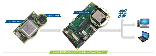
Let’s start with the physical medium. Signals typically arrive through a twisted pair copper cable to an Ethernet jack with magnetics on our Carrier Board, then continue through impedance matched differential traces on the PCB to the Ethernet PHY IC. This device converts analog signals from the medium to digital signals for the processor and vice versa.
The electrical signals first encounter the Medium Dependent Interface (MDI) of the PHY, a part of the Physical layer. Different physical media have different characteristics. In accordance with the specific kind of the media, the signals are transformed and sent to the next layer of the OSI-model, the Data Link Layer. We provide 10Base-T and 100Base-TX (Fast Ethernet) on our Colibri Modules and 1000Base-T (Gigabit) on the Apalis modules. The standardized interface between the first two OSI-layers is called Media Independent Interface (MII) and is independent of the physical layer.
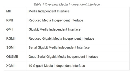
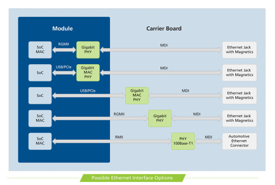
Meanwhile, we are talking about the advanced backward-compatible Reduced Gigabit Media Independent Interface (RGMII) and the next interface for the 10 Gigabit is already named as XGMII. Reduced means that there are fewer signals needed for the same standard. The xMII’s are parallel data buses. There is a supplementary serial bus for management purpose called Management Data Input/Output (MDIO). The xMII interface ends at the Media Access Control (MAC) layer. Here the well-known MAC address is used as a unique identifier. The MAC layer can be integrated with the System on Chip (SoC), like on NXP® processors. But it could be already embedded in the same IC as the PHY, which is better known as an Ethernet Controller. The Ethernet Controller IC, in turn, is connected with the SoC through a separate interface like USB or PCIe. Note that we are not looking at higher OSI layers and protocols like ARP, NDP, IP, TCP, UDP, etc., which are organized in frames and packages, because for all these protocols the electrical characteristics on the first physical levels are the same!
For now, let’s go back to the physical layer. There are 2 main characteristics of the physical link I’d like to expand on, namely, speed and duplex mode. Our modules support speeds up to 1Gbit on Apalis Modules and 100Mbit on Colibri Modules, and both half and full duplex modes. In full duplex mode of operation, PHYs on both ends of the link can communicate with each other simultaneously. For the half duplex mode, where the PHY can’t receive and transmit data at the same time, there need to use the Carrier Sense Multiple Access with Collision Detection (CSMA/CD) to avoid collisions and control the data flow.
As already described, our Apalis Modules are capable of Gigabit Ethernet, but how do the communication partners know with which speed they can send the data? An-auto negotiation procedure exists, where the linking partners set the best link trough 16ms link pulses. Please be careful with auto-negotiation settings, as there is a well-known problem of the duplex mismatch, when the linking partners are configured in a fixed way. On the electrical side of the physical layer 10Base-T and 100Base-TX use two twisted pairs while 1000Base-TX uses 4. 100Base-TX is faster than 10Base-T based on the much faster frequency of 62.5 MHz instead of 10 MHz and denser signal modulation scheme (PAM-3). 1000Base-TX uses the same frequency as 100Base-TX, but transmits across 4 twisted pairs and with a higher level of modulation (PAM-5). Finally, there is an additional feature called EEE, Energy Efficient Ethernet. The aim of this standard is to save energy.
https://www.analog.com/media/en/technical-documentation/application-notes/EE-269.pdf
https://en.wikipedia.org/wiki/Duplex_mismatch
https://en.wikipedia.org/wiki/Media-independent_interface
https://www.asix.com.tw/new_alias.php?alias=93&full=http://www.embedded.com/design/202804534
The picture below summarizes the Ethernet possibilities on the Toradex SoM approach:
Automotive Ethernet
Before we continue to the Compliance Testing, I want to quickly let you know that I receive a lot of questions about 100Base-T1, better known as Automotive Ethernet. The customers want to know, if it is possible to connect Automotive Ethernet to a fast Ethernet PHY. The 100Base-T1 has a different physical layer specification to fulfill the requirements in a harsher automotive environment. It is not possible to connect it, but the MII is still the same! The solution is to connect the 100Base-T1 PHY to the Multimedia Independent Interface of the SoC directly. Consequently, a Module with an xMII on the Module Edge Connector must be selected! Of course, you have to design your Custom Carrier Board with a 100Base-T1 PHY. Here you can find the list of Toradex Modules which provide an xMII on the edge connector. Please note that this is not a Standard Toradex Interface and the pin assignment varies with each module.
Apalis iMX8
Colibri iMX8X
Colibri iMX7
Colibri iMX6ULL
Colibri Vybrid
Ethernet Compliance Testing for Toradex Systems

Figure 2 10Base-T Test: DOV Internal MAU Normal
After this very short overview, I want to continue with the compliance testing, where we test the electrical signals in time and voltage. The electrical signals look totally different for the 10/100/1000 Mbps and have different requirements as you can see in the oscillograms.
The tests evaluate the voltage amplitudes, jitter values, rise/fall times and other signal characteristics. For each test a defined test signal must be generated by the DUT, e.g. a continuous pseudo-random signal has to be emitted. The easiest way to test the signal requirements is to define a test mask. The signals must not intersect with the mask in order to fulfill the specification. The 10Base-T tests are very often defined through a test mask, as you can see in the first figure. I want to mention some values: The Peak Differential Output Voltage must be between 2.2 V and 2.8 V. The Differential Output Voltage Harmonics must be greater than 27 dB and all Jitter values must be smaller than 22 ns. Very interesting is the twisted-pair model for 10Base-T, which must be used for some compliance tests. With the equivalent circuit based on lumped elements, it is possible to model multiple different transmission elements with just passive components. Depending on the PHY a linking partner is needed for 10Base-T compliance tests. You can download the Test Report of Colibri iMX6ULL as an example, where you can find all tests.

Figure 3 Measured differential random 10Base-T signal without load
The interface characteristics for 100Base-TX are defined in table 2 based on the MLT-3 voltage signals with three levels. The data is encoded before with 4B5B algorithm, so a clock recovery out of the data stream is possible because a level transition is forced. For our test equipment, a pseudo-random test pattern (PRBS7) is enough for all the tests. However, some tests only trigger on defined patterns and measures only at that moment the specific values.
Table 2 Interface Characteristics 100Base-TX Characteristics Min Max Unit UTP DOV Base to Upper/Lower 950 1050 mV Signal Amplitude Symmetry 98 102 % Rise/Fall Time 3 5 ns Rise/Fall Time Symmetry 0 500 ps Duty Cycle Distortion -250 250 ps Transmit Jitter 0 1.4 ns Overshoot 0 5 %

Figure 4 Measured differential random signal 100Base-TX
The test criteria are defined in a similar manner for the 1000Base-T. I am not going to list them. For these tests an additional disturber in the form of an Arbitrary Waveform Generator (AWG) is needed to create the required disturbing signals with the frequency of 31.25 MHz and 20.833 MHz. In figure 5 you can see the test pattern of test mode 1 produced by the PHY. There are four different test patterns, which can be generated through PHY’s MDIO register settings. Please don’t forget that we have to perform the compliance test four times, because of the four twisted pairs.

Figure 5 Definition of Test Mode 1 Waveform 1000Base-T from IEEE Standard for Ethernet

Figure 6 Measured differential Test Mode 4 Distortion Test 1000Base-T without disturber
We have now seen some of the electrical requirements that must be fulfilled to be compliant with the interface definition. Before we have a closer look at the test equipment, I want to try and solve the most important question of this Blog: How do you generate those test signals?
Each PHY vendor has a custom method to modify the necessary register settings to enter the test modes. That is often not publicly available, and you must ask your PHY vendor. A very good example is Microchip, who has provided all information about Ethernet Compliance in one document since last year. These are the Ethernet PHYs, which we use in our modules, KSZ8041 and KSZ9031. I also want to share a document from TI with you, just as a further example. If you are looking for a new Ethernet PHY and want to do Ethernet Compliance Testing, please ask your vendor for detailed information about the register settings in advance!
http://ww1.microchip.com/downloads/en/AppNotes/AN2686-Ethernet-Compliance-Test-10BASET-100BASETX-1000BASET.pdf
http://www.ti.com/lit/an/snla239a/snla239a.pdf
Test Equipment
As depicted above, we must measure some picoseconds precisely. For that we need very good tooling. You should use an oscilloscope with a bandwidth of 1 GHz and memory of 4MS or greater. Usually you need a test fixture, which transforms the Ethernet signals from an Ethernet Jack to the oscilloscope input channels. That is why we work closely with Teledyne LeCroy. We have a great collaboration on a technical level. We use a high-end oscilloscope from the WaveMaster series with appropriate hardware and software tools. Of course, there is equipment from other vendors available like Tektronix, Rhode&Schwarz, Keysight and others.
Quotation from Mr. Hofferbert, specialist at Teledyne LeCroy:
“Teledyne LeCroy is a leading manufacturer of digital storage oscilloscopes (DSO). With modern DSOs it is possible to perform qualification measurements. Toradex uses appropriate equipment from Teledyne LeCroy to test the design of Ethernet PHYs. With the combination of our QualiPHY Software and latest oscilloscopes, a semi-automatic test has been implemented to test the physical level of the Ethernet PHYs according to the IEEE 802.3 specification. This measurement solution allows the development engineers at Toradex to test and resolve issues with signal integrity in an early development stage of their embedded systems. Toradex is very interested in using the measurement equipment as efficiently as possible. If there are any uncertainties or measurement deviation, we work together to quickly solve these issues and provide our expertise in measurement application.” Gregor Hofferbert, Teledyne LeCroy
www.teledynelecroy.com
http://cdn.teledynelecroy.com/files/manuals/qualiphyenetmanual.pdf
Conclusion
After performing a compliance test, we can create a compliance report to verify our PCB design. As you can see in the test report from Teledyne LeCroy, the Colibri iMX6ULL with Iris Carrier Board is compliant with 10Base-T and 100Base-TX standard. So, we are sure that our implementation will work with other compliant systems. We can share with confidence our PCB implementation of the Ethernet Interface with our customers. You can find the Carrier Board Design Guides here: https://developer.toradex.com/carrier-board-design
We also share our Carrier Boards Designs as Altium Designer projects for free with our customers. We provide a lot of help through our community channel as well: https://www.toradex.com/community
We started to implement and provide our testing SW in our latest BSP. We adopt the existing drivers to be easily run with our modules to perform Compliance Tests. But again be careful, for each PHY you need different SW techniques to get the test pattern. There is no simple handbook. For example: https://git.toradex.com/cgit/linux-toradex.git/commit/?h=tegra-next&id=13bd0f089ac6babeb7248fe3db4b9c19233cce3c
But issues can occur with wrong routing, bad ground layout, or inaccurate crystal circuit design. It also depends on the testing environment. Ground loops and noisy or underpowered power supplies can cause measuring errors. It is important to follow the design guides of the PHY vendors. I like the troubleshooting document provided by Intel, that you can use for the first debug consultation. There is a basic overview of failures and possible sources. Designs with too long traces, low quality magnetics or improper use of the measurement equipment can always be the source of failing the compliance test. But there are also specific errors which can be put in a strong correlation. E.g. wrong amplitude values are often caused by wrongly assembled bias resistors or issues with the centre tap circuits. Whereas too high Jitter values are due to crystal issues, impedance mismatch or bad power supply. In general, your Ethernet PHY vendor should be able to help you, probably even with a schematic or layout review.
https://www.intel.com/content/dam/www/public/us/en/documents/application-notes/ieee-conformance-phy-app-note.pdf
In this blog, I gave you some insights to one of the many verifications Toradex does to achieve such high-quality products. Internal testing by us and your adherence to our design guides reduces your risk to a minimum. For the highest quality, you can do your verification with your own customized carrier board, and that you follow the system engineering approach (as documented by NASA, for instance) which recommends testing in early stages to reduce risk and cost. I hope I gave you plenty of information to get started. If you need more information feel free to reach out.
#Ethernet Compliance Test#Apalis iMX8#Colibri iMX6Ull#Development Boards#NXP i.MX 8#NXP i.MX 6ULL#System on Module#Computer on Module
0 notes
Text
The i.MX8 cannot be deblobbed (when using HDMI)
https://www.devever.net/~hl/imx8 Comments
0 notes
Video
vimeo
IMX8-Demo-Unboxing from Gamry Instruments on Vimeo.
0 notes
Text
The king of HarmonyOS mobile phones is here: Huawei P60 key details revealed
According to recent reports, the Huawei P60 series won’t be official until March 23, 2023. This device will come with the new HarmonyOS 3.0. The company will hold a new product press conference where it will officially unveil this new flagship. Huawei will restart its one-year dual flagship new product pattern with the release of the Huawei P60 series. This means that the company will launch the P series in the first half of the year and the Mate series in the second half.

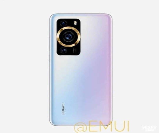
As usual, the Huawei P60 series will have a few models. From the reports so far, this series will have three models including Huawei P60, P60 Pro and P60E. Over the past few months, there have been a lot more details about this device. The Huawei P60 series will be powered by the same Qualcomm Snapdragon 8+ Gen 1 flagship chipset as the Huawei Mate50 series. It employs an eight-core architecture and is built using TSMC’s 4nm tech. Unfortunately, this device will still not support 5G network. However, looking at the response so far from the market, 5G is not of great importance. At the moment, it has no impact on the purchases of mobile phones. After all, every year’s P series flagship will use the same processor as the previous year’s Mate series, going by Huawei’s prior practice of using its own chips. Huawei P60 design The Huawei P60 series will reportedly have a rectangular modular design in terms of appearance. This device will also have a flash in the upper right corner, a tiny lens in each of the upper left and lower left corners, and a big circular lens in the center. From the comments so far, while this device still looks good, it’s not as good as the Huawei P50. In my humble opinion, the Huawei 60 has indeed made a daring effort to change when compared to the look of its predecessor. The visual emphasis is sharper after the adjustment.

In the camera department, the Huawei P60 series gets a complete overhaul. A Sony IMX8 series lens, which enables optical image stabilization, will be used on the primary camera. A 50MP ultra-wide-angle plus a 64MP telephoto lens make up the auxiliary camera. In addition, it will be comparable to the Mate50 from the previous year. Along with having a changeable aperture, the lens will also be able to produce XMAGE super optical variable pictures. Inevitably, Huawei should slowly permit all mobile phones to support this imaging tech. Specs The Huawei P60 Pro is also rumoured to have a 6.6-inch OLED screen with a resolution of 3200 x 1440. It will also support a 120Hz frame rate and 1920Hz high-frequency PWM dimming. Under the hood, this device comes with a built-in battery of 5000 mAh. This battery will support both 100W typical fast charging and 50W wireless fast charging. According to rumours, the Huawei P60 series will utilize Kunlun glass similar to that found on the Mate 50 series. This device will also enable Beidou satellite connectivity and include Hongmeng OS 3.0. In fact, the company calls this device the “King of HarmonOS” because it may come with very new Harmony-exclusive features. At present, the biggest suspense of the Huawei P60 series leaks so far is the price. It is worth noting that after the launch of this new series, naturally, the price of the previous Huawei P50 series will drop.

History of the Huawei P series
Huawei’s P series is a line of flagship smartphones that the company launched in 2012. Since then, Huawei has released a new P series phone every year, typically in the first half of the year. Here’s a brief overview of the history of Huawei’s P series: Huawei P1 (2012) The first phone in the P series, the Huawei P1, was released in May 2012. It comes with a 4.3-inch display, a dual-core processor, and an 8MP camera. Huawei P2 (2013) The second phone in the P series, the Huawei P2, was released in February 2013. It uses a 4.7-inch display, a quad-core chip, and a 13MP camera. Huawei P6 (2014) The Huawei P6, released in June 2014, was one of the thinnest smartphones of its time at only 6.18mm thick. It uses a 4.7-inch display, a quad-core processor, and an 8MP camera. Huawei P7 (2014) The Huawei P7 was released in May 2014, just a month before the P6’s one-year anniversary. It features a 5-inch display, a quad-core chip, and a 13MP camera. Huawei P8 (2015) The Huawei P8 was released in April 2015. It features a 5.2-inch display, an octa-core chip, and a 13MP camera with optical image stabilization. Huawei P9 (2016) The Huawei P9 was released in April 2016. It uses a 5.2-inch display, a dual-camera setup (co-engineered with Leica), and a Kirin 955 SoC. Huawei P10 (2017) The Huawei P10 was released in February 2017. It comes with a 5.1-inch display, a dual-camera setup (co-engineered with Leica), and a Kirin 960 SoC.

Huawei P20 (2018) The Huawei P20 was released in March 2018. This device features a 5.8-inch display, a dual-camera setup (co-engineered with Leica), as well as a Kirin 970 SoC. Huawei P30 (2019) The Huawei P30 was released in March 2019. Also, it features a 6.1-inch display, a triple-camera setup (co-engineered with Leica), and a Kirin 980 SoC. Huawei P40 (2020) The Huawei P40 was released in April 2020. It features a 6.1-inch display, a triple-camera setup (co-engineered with Leica), and a Kirin 990 chip. Huawei P50 (2021) The Huawei P50 was released in July 2021. It also features a 6.5-inch display, a dual-camera setup, and a Kirin 9000 SoC. It is worth noting that the later models in the series, particularly those released after 2019, have faced challenges with Western markets due to concerns over Huawei’s ties to the Chinese government and allegations of espionage. This has led to restrictions on Huawei’s access to some key techs, such as Google Mobile Services, which has affected the company’s ability to sell its devices outside of China. Read the full article
0 notes
Text
تسريبات تقدم تفاصيل جديدة حول مستشعر Sony IMX989
تسريبات تقدم تفاصيل جديدة حول مستشعر Sony IMX989
تقدم شركة سوني قريباً مستشعر Sony IMX989 الذي يدعم هاتف شاومي Xiaomi 12 Ultra، ولقد أوضحت أحدث التسريبات تفاصيل المستشعر المرتقب قبل الإعلان الرسمي.أشارت تسريبات سابقة إلى أن سوني تدعم Vivo X80 Pro المرتقب بمستشعر من سلسلة IMX8 ليكون المستشعر الرئيسي في الهاتف، واليوم تأتي تسريبات جديدة حول مستشعر IMX989 القادم من سوني. ولقد جاءت التفاصيل الجديدة عبر “DigitalChatStation” على منصة Weibo، حيث أكدت…

View On WordPress
0 notes
Text
مواصفات فيفو اكس 80 - vivo X80 وبقية هواتف السلسلة بأحدث التسريبات
مواصفات فيفو اكس 80 – vivo X80 وبقية هواتف السلسلة بأحدث التسريبات
قبل أسابيع قليلة ، كشفت الشائعات أن هاتف فيفو اكس 80 – vivo X80 سيدعم مستشعر Sony IMX8-series الجديد. ومع ذلك ، لم يكن هناك أي دليل حول المستشعر الدقيق ونوعه. أما الآن ، كشف تسريب جديد من BaldPanda عن بعض التفاصيل حول هذا المستشعر الذي يزيد الإغراء أكثر لإصداره الرسمي. ويكشف المسرب أن vivo X80 سيأتي مع عدسة رئيسية Sony IMX886. سيكون المستشعر 1 / 1.56 بوصة وسيتبنى ترتيب RGBW. لسوء الحظ ، لم يكشف…
View On WordPress
0 notes
Photo

Embedded NXP i.MX8 Board Supports Dual CAN Bus Port
Avnet Integrated announced the release of their scalable MSC SM2S-IMX8Plus SMARC 2.1 module family, integrating the i.MX 8M Plus processor from NXP.
The modules utilize the 1.8-GHz dual- or quad-core Arm Cortex-A53 processors plus the 800-MHz Arm Cortex-M7 real-time processor plus the GC7000UL 2D/3D graphics processing unit (GPU). Several options are available with and without the video processing unit (VPU), machine learning accelerator (NPU), or image signal processor (ISP). The board supports up to 4-GiB SDRAM and up to 256-GiB eMMC Flash memory (optional) for application and data storage. The embedded interfaces include two Gbit/s-Ethernet connections, PCI Express, USB 3.0, USB 2.0, and two CAN Bus ports.
https://copperhilltech.com/blog/embedded-nxp-imx8-board-supports-dual-can-bus-port/
0 notes
Text
Xiaomi Mi Note 10 Lite comes with 8 GB RAM, 4 cameras

Note 10 Lite Price, Pros, Cons Review & specification Xiaomi Mi Note 10 Lite comes with 8 GB RAM, 4 cameras, huge battery:- Finally, Xiaomi officially released the Mi Note 10 Lite phone in the Bangladesh market. In addition to the quad-camera phone, Xiaomi has also announced the launch of six new service centers to make Xiaomi phones accessible to all. Just a few days ago, they unveiled the Poco X3 NFC phone globally. And today I brought this light model of Mi series to Bangladesh. Let's find out now about the Mi Note 10 Lite. Note 10 Pros & Cons Display The Xiaomi Mi Note 10 Lite has a 6.48-inch curved AMOLED display. The screen-to-body ratio of the phone's display is 91.4 percent, with a resolution of 1080 * 2340 pixels. The phone has an in-display fingerprint sensor. Gorilla Glass 5 on the front and back will protect the device. Android 11 OS has come on Xiaomi, OPPO, Realme phones Google Pixel 4A pros cons & review Mi Note 10 light camera Sony's IMX8 sensor has a 64-megapixel main camera. It also has an 8-megapixel ultra wide camera, a 5-megapixel depth sensor and a 2-megapixel macro camera. There is a 16 megapixel front camera in front of the phone as a selfie camera. Features like 960 fps slow motion, 4K video recording. Read the full article
0 notes
Text
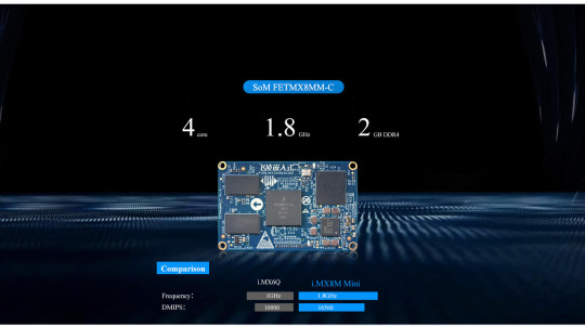
Introducing the FETMX8MM-C System on Module (SoM) powered by NXP's i.MX8M Mini processor!
🚀 Unlock the potential of a 1.8GHz Cortex A53 quad-core and single Cortex M4 core, tailored for diverse IoT and industrial applications. Featuring 2GB DDR4, USB 2.0, Bluetooth, optional WiFi, PCIe 2.0, and robust multimedia capabilities. With support for Android 9.0 and Linux 4.14, elevate your embedded projects with the cutting-edge i.MX8M Mini SoM.
0 notes
Text
Toradex opens Early Access for the Apalis iMX8 with the NXP i.MX 8QuadMax SoC
Toradex announced that it has opened early access for selected customers to its new Apalis iMX8 System on Module (SoM) based on the NXP® i.MX 8QuadMax SoC.

Companies interested in working with this cutting-edge Hardware and Software are invited to sign up for the Toradex early access program to receive more information about the requirements to join the program.
The Apalis iMX8 is the latest member of the Apalis family, a high-performance Arm®-based pin-compatible SoM. The NXP i.MX 8QM SoC is the highest performance variation of the i.MX 8 family, featuring 6x Armv8-A 64-bit processor cores – 2x Arm Cortex-A72 & 4x Cortex-A53 – as well as 2x additional Cortex-M4F microcontrollers. The integrated HIFI4 DSP, a high-performance dual GPU, 28 nm FD-SOI technology, and extra safety features are other differentiators to the lower performance i.MX 8M SoC.
The release version of the Apalis iMX8 will come with all the standard Toradex advantages including Toradex Easy Installer, Free Professional Support, Production-quality Yocto Project Based Linux BSP, Active Community, Daily updated Developer Page, Pin-out Designer tools, Fully open Carrier Board Designs, World Wide Network with local support offices and much more.
Toradex Partners are already working for solutions on top of Toradex SoM offerings; this includes Graphical User Experience, Deep Learning Inference Optimization, Machine Vision Tools, and additional Operating Systems.
At Embedded World 2018, Toradex showcased the Apalis iMX8 in two interesting demos: demonstrating the Toradex MIPI CSI-2 Camera Module and showing Qt 3D Studio taking advantage of the dual 3D GPU.
For a brief overview of the demos at Embedded World 2018, please see:
youtube
Apart from its high performance and rich interfaces, the i.MX 8QuadMax stands out with long availability of over 10 years. The SoC is built with 28 nm FD-SOI technology to reduce soft errors and increase MTBF. High shock and vibration resilience and a temperature range from -40° to 85°C, makes the Apalis iMX8 a great choice for edge computing applications in the most demanding environments.

Block Diagram: NXP i.MX 8QM
Critical real-time and safety processes can be off-loaded to the dual Cortex-M4F coprocessors. The latest iteration of the NXP Asynchronous Hybrid System with Cortex-A and Cortex-M class processors isolates the M4 cores to provide the highest safety. OpenCL 2.0 allows the GPUs on the i.MX 8QM to be used not just for graphics, but also for Computer Vision, Machine Learning and Signal Processing.
The samples available for the early access feature 4GB RAM and up to 16GB Flash Memory. Toradex has also opened the forum to the public to provide input for the final modules configurations: https://www.toradex.com/computer-on-modules/apalis-arm-family/nxp-imx-8#features
About Toradex:
Toradex is a Swiss-based company with offices around the world, offering Arm®-based System on Modules (SoMs) and Customizable Single Board Computers (SBCs). Powered by NXP® and NVIDIA® SoCs, the pin-compatible SoMs are ideal for demanding edge computing applications. Toradex SoMs offer scalability in terms of price, performance, power consumption and I/Os. Complemented with direct online sales and long-term product availability, Toradex offers direct premium support and ex-stock availability with local warehouses. Toradex SoMs come with a free production-quality Linux BSP based on the Yocto Project.
#Apalis iMX8#iMX8 Early Access#NXP i.MX 8QuadMax SoC#iMX8 System on Module#iMX8 Computer on Module#Machine Vision#28 nm FD-SOI technology#deep learning
0 notes
Text
Customizable compute module and eval kit run Linux on i.MX8X
Customizable compute module and eval kit run Linux on i.MX8X
[ad_1]
CompuLab’s rugged “CL-SOM-iMX8X” module runs Linux on a quad -A35 i.MX8X and offers up to 4GB LPDDR4 and 64GB eMMC, up to 2x GbE, and optional 802.11ac/BT 4.2. There’s also a $395 eval kit. CompuLab, which has previously launched NXP i.MX8M-based CL-SOM-iMX8 and i.MX8M Mini based UCM-iMX8M-Mini modules, has now returned with a module that supports the i.MX8X. Like the CL-SOM-iMX8, the…
View On WordPress
0 notes
Text
Embedded Hardware Software for Your Project
We specialize in the following:
TI Sitara, sitara processor, single board computers, SCADA industrial hardware, Quectel LTE modem, embedded projects, industrial mini pc, sitara ARM cortex processor, single board computer, SCADA device, evaluation board, RS485 , RS232, CAN, linux board, industrial hardware with RS232, industrial computer, gnu arm embedded toolchain, FreeRTOS, fanless CPU, embedded project SCADA, embedded data acquisition, embedded beaglebone black, ARM processor, ARM CPU, arm gcc compiler, arm gcc, ARM cortex A8 CAN, ARM chipset, A8 processor, cubox i, IMX6, IMX8, and Raspberry pi.
Key Features
It is a custom beaglebone dark intended to meet modern necessities.
Can straightforwardly associate mechanical RS232, RS485, and Ethernet gadgets
WiFi has a radio wire gain of 4dBi and backings remote gauges IEEE802.11n, IEEE 802.11g, IEEE 802.11b
WiFi recurrence: 2.4-2.4835GHz
WiFi exchange rate 11n: Up to 150 Mbps (dynamic)
The unit can work in Ad-Hoc/Infrastructure mode
WiFi Security underpins 64/128 piece WEP, WPA-PSK/WPA2-PSK
WiFi transmission control: < 20dBm
LTE Modem is good with 4G LTE CAT6 systems and offers Download speed of up to 300 Mbps and Upload accelerate to 50 Mbps
LTE Modem bolsters Dual Carrier HSPA+ and prior adaptations of HSPA+
LTE Modem bolsters WCDMA 850/900/2100 MHz
LTE Modem underpins External Antenna connector
LTE Modem gives GPS data
The framework bolsters double boot utilizing SD card or eMMC. On the off chance that the gadget neglects to boot from SD card, at that point the eMMC picture is utilized
The processor keeps running on custom Linux having 4.9.69 part
The gadget can course any information from WiFi (AP mode), Ethernet, RS232 or RS485 over LTE modem
The unit depends on AM335x 1GHz ARM® Cortex-A8 with 512MB DDR3 RAM, 4GB eMMC stockpiling , 4GB SD card stockpiling
Programming can be altered to modify the CPU at different rates amid various stages to advance the aggregate power utilization.
Furthermore, CPU can be placed in reserve/rest mode and can be woken up on a GPIO0 PIN interfere.
Backings B30 (2300 WCS), B41 (TDD 2500), B29 (US 700de Lower), B26 (US 850 Ext), B25 (1900), B5 (850), B20 (800DD), B13 (700c), B12 (700ac), B7 (2600), B4 (AWS), B3 (1800), B2 (1900), B1 (2100)
LTE Region: Europe, North America , Asia South America, Africa
youtube
0 notes
Video
youtube
OKMX8MP-C Single Board Computer Demo | iMX8M Plus NXP based
0 notes