#nonlinear structural analysis software
Explore tagged Tumblr posts
Visit Tumblr Blog
Explore Tumblr blogs with no restrictions, modern design and the best experience.
Last Seen Tumblr Blogs


Fun Fact
Tumblr has a 66 index score for customer satisfaction in the US.
Text
Extreme Loading specializes in nonlinear structural analysis, offering advanced nonlinear structural analysis software for engineers. Our innovative tools enable precise modeling of complex structures under dynamic loading conditions. Designed for efficiency and accuracy, our software empowers engineers to optimize designs and enhance safety in their projects.
1 note
·
View note
Text
Advanced Solutions with Nonlinear Structural Analysis Software
Structural engineering is evolving, and traditional analysis methods are no longer enough to predict how structures behave under extreme conditions. Nonlinear structural analysis software provides engineers with advanced tools to assess material and geometric nonlinearity, ensuring more accurate predictions of structural performance. This technology is crucial in industries such as civil engineering, aerospace, and infrastructure development, where safety and durability are top priorities. By simulating real-world conditions like seismic activity, blast loads, and progressive collapse, nonlinear structural analysis helps engineers design safer and more resilient buildings.
Unlike linear analysis, which assumes a proportional relationship between loads and deformations, nonlinear structural analysis software accounts for complex behaviors such as plastic deformation, buckling, and fatigue. Engineers use this software to study dynamic loads, time-dependent effects, and extreme forces that could compromise a structure’s integrity. With highly accurate simulations, they can make design adjustments before construction begins, preventing costly failures and improving safety. By incorporating nonlinear structural analysis, engineers gain deeper insights into structural performance, ensuring that buildings and infrastructure can withstand harsh environmental conditions.
As engineering technology advances, nonlinear structural analysis software is becoming more powerful and accessible. Cloud-based computing, AI-driven analysis, and improved simulation techniques are transforming how engineers approach structural design. These innovations allow for faster computations, enhanced visualization, and improved collaboration among teams. Investing in advanced nonlinear structural analysis solutions ensures better safety, efficiency, and cost savings.
Read our blog to explore how this technology is reshaping the future of structural engineering and why it is a must-have tool for modern professionals.
0 notes
Text
Choosing the Right Software for Concrete Design: Features, Benefits, and Industry Applications
The construction and infrastructure sectors are evolving rapidly, and with growing demands for speed, safety, and sustainability, relying solely on manual methods for structural design is no longer feasible. This is especially true for concrete-based construction projects. From buildings to bridges and precast elements, precise structural calculations and compliance are essential. That’s where software for concrete design becomes a critical asset.
At Index Infotech, we help engineering and construction firms embrace digital transformation with integrated solutions that streamline design, production, and delivery—especially in the precast and concrete sectors.
What is Concrete Design Software?
Concrete design software is a digital engineering tool that enables civil and structural engineers to design, analyze, and simulate concrete structures. These platforms help automate load calculations, structural reinforcement design, compliance checks, and generate technical drawings—all in alignment with international standards such as ACI, Eurocode, IS456, and others.
Whether it’s cast-in-situ, prestressed, or precast concrete, using the right software can dramatically improve both design quality and execution efficiency.

Key Features to Look for in Concrete Design Software
1. Advanced Structural Analysis Tools
The best software supports 2D and 3D analysis of slabs, beams, columns, and entire building frames. It should handle complex load combinations, dynamic loads, and nonlinear behavior with ease.
Tip: Look for finite element analysis (FEA) capabilities and integration with BIM tools.
2. Code Compliance and Localization
Every region follows different concrete design codes. Your software should support multiple international standards and offer customization for local guidelines.
Supported Codes to Look For:
ACI 318 (USA)
Eurocode 2 (EU)
IS 456 (India)
BS 8110 (UK)
3. Integrated BIM & CAD Support
Modern construction relies on coordination and collaboration. BIM-compatible concrete design software allows seamless sharing of models with architects, MEP consultants, and contractors.
Benefit: Minimizes design conflicts and streamlines project timelines.
4. Precast and Modular Design Capabilities
For companies working with precast concrete, software should support mold planning, reinforcement detailing, and segmental design. At Index Infotech, we specialize in solutions that integrate design with ERP workflows for smarter precast production.
5. Automated Drawing Generation and Reports
Design software should enable automatic generation of structural drawings, rebar schedules, and design reports that are ready for site execution or submission.
Key Benefits of Using Concrete Design Software
Faster Design Cycles
Automation eliminates repetitive calculations, allowing teams to complete designs in a fraction of the time.
Improved Accuracy
With real-time error checking, load validations, and visual modeling, the risk of design errors is significantly reduced.
Cost Savings
Efficient material optimization and reduced rework lead to lower project costs and more competitive bids.
Better Project Planning
When integrated with ERP systems, design data can flow directly into project scheduling, procurement, and production planning.
Industry Applications of Concrete Design Software
Commercial & Residential Buildings
Precast Concrete Manufacturing
Infrastructure Projects (Bridges, Flyovers)
Industrial Foundations
High-Rise Structural Design
Tunnel and Retaining Wall Systems
At Index Infotech, we support clients in all of these sectors with tailored solutions that improve structural integrity while reducing project overheads.
Why Choose Index Infotech?
Precast-Focused Expertise: We offer specialized tools and consulting for precast concrete design and integration with ERP platforms.
Industry-Aligned Solutions: Our software supports global and regional design codes, making it ideal for firms with international projects.
Seamless Integration: Combine structural design with production, procurement, and financial planning for complete digital control.
End-to-End Support: From training to customization, our team ensures that you extract maximum value from your concrete design software.
Conclusion
Choosing the right software for concrete design is about more than just drawing capabilities—it’s about ensuring accuracy, compliance, speed, and scalability across your projects. Whether you’re designing foundations, structural frames, or precast components, the right tool can set your business apart.
Partner with Index Infotech to unlock a new era of precision, productivity, and performance in concrete construction.
1 note
·
View note
Text
Unlock the Full Potential of Engineering Simulation with Femap
In today’s highly competitive manufacturing and engineering landscape, simulation-driven design is not just an advantage — it’s a necessity. Engineers and analysts need robust tools that offer high performance, accuracy, and flexibility without unnecessary complexity or cost. This is where Femap, a Siemens Digital Industries Software product, steps in. As a standalone finite element analysis (FEA) pre- and post-processor, Femap empowers engineers to model, simulate, and visualize complex engineering systems.
What is Femap?
Femap is an advanced engineering simulation tool used to build finite element models of complex products or systems and to evaluate them under real-world conditions. It works seamlessly with NX Nastran or other solvers, enabling users to conduct detailed structural, thermal, and dynamic simulations. This makes Femap a vital solution for CAE professionals who require deep insights into product performance — before any physical prototype is built.
Key Features
Integrated pre- and post-processor
CAD-independent geometry import and clean-up
Advanced meshing and geometry editing tools
Linear and nonlinear simulation capabilities
Fatigue, vibration, and thermal analysis
Solver-neutral architecture
Custom automation using APIs
Easy model comparison and error checking
Benefits of Using Femap
✅ Accelerate Product Development: Perform virtual tests early and reduce dependency on physical prototypes.
✅ Reduce Costs: Lower material waste and redesign efforts with more accurate simulation.
✅ Improve Product Reliability: Identify stress points and failure modes before manufacturing.
✅ Enhance Collaboration: Share detailed simulation insights across teams and stakeholders.
✅ Boost Innovation: Simulate complex scenarios and explore design alternatives with ease.
✅ Easy Integration: Works with popular CAD systems and various solvers, making implementation seamless.
Why DDSPLM for Femap?
Choosing the right technology partner is just as critical as choosing the right software. DDSPLM is a trusted Siemens Digital Industries Software partner with years of domain expertise in PLM, CAD, and simulation technologies. Here’s why customers choose DDSPLM for Femap:
✔️ Certified Siemens Solution Partner
✔️ Expert Consultation & Implementation Support
✔️ Industry-Specific Customization
✔️ Ongoing Training & Technical Assistance
✔️ Strong Post-Sales Service & Maintenance
✔️ Experience Across Automotive, Aerospace, Electronics & More
If you’re looking to advance your simulation capabilities with a powerful, reliable, and cost-effective tool, Femap is the solution of choice. And when partnered with DDSPLM, you get more than just software — you gain a long-term technology partner committed to your success.

0 notes
Text
Robert Pierce, Co-Founder & Chief Science Officer at DecisionNext – Interview Series
New Post has been published on https://thedigitalinsider.com/robert-pierce-co-founder-chief-science-officer-at-decisionnext-interview-series/
Robert Pierce, Co-Founder & Chief Science Officer at DecisionNext – Interview Series

Bob Pierce, PhD is co-founder and Chief Science Officer at DecisionNext. His work has brought advanced mathematical analysis to entirely new markets and industries, improving the way companies engage in strategic decision making. Prior to DecisionNext, Bob was Chief Scientist at SignalDemand, where he guided the science behind its solutions for manufacturers. Bob has held senior research and development roles at Khimetrics (now SAP) and ConceptLabs, as well as academic posts with the National Academy of Sciences, Penn State University, and UC Berkeley. His work spans a range of industries including commodities and manufacturing and he’s made contributions to the fields of econometrics, oceanography, mathematics, and nonlinear dynamics. He holds numerous patents and is the author of several peer reviewed papers. Bob holds a PhD in theoretical physics from UC Berkeley.
DecisionNext is a data analytics and forecasting company founded in 2015, specializing in AI-driven price and supply forecasting. The company was created to address the limitations of traditional “black box” forecasting models, which often lacked transparency and actionable insights. By integrating AI and machine learning, DecisionNext provides businesses with greater visibility into the factors influencing their forecasts, helping them make informed decisions based on both market and business risk. Their platform is designed to improve forecasting accuracy across the supply chain, enabling customers to move beyond intuition-based decision-making.
What was the original idea or inspiration behind founding DecisionNext, and how did your background in theoretical physics and roles in various industries shape this vision?
My co-founder Mike Neal and I have amassed a lot of experience in our previous companies delivering optimization and forecasting solutions to retailers and commodity processors. Two primary learnings from that experience were:
Users need to believe that they understand where forecasts and solutions are coming from; and
Users have a very hard time separating what they think will happen from the likelihood that it will actually come to pass.
These two concepts have deep origins in human cognition as well as implications in how to create software to solve problems. It’s well known that a human mind is not good at calculating probabilities. As a Physicist, I learned to create conceptual frameworks to engage with uncertainty and build distributed computational platforms to explore it. This is the technical underpinning of our solutions to help our customers make better decisions in the face of uncertainty, meaning that they cannot know how markets will evolve but still have to decide what to do now in order to maximize profits in the future.
How has your transition to the role of Chief Science Officer influenced your day-to-day focus and long-term vision for DecisionNext?
The transition to CSO has involved a refocusing on how the product should deliver value to our customers. In the process, I have released some day to day engineering responsibilities that are better handled by others. We always have a long list of features and ideas to make the solution better, and this role gives me more time to research new and innovative approaches.
What unique challenges do commodities markets present that make them particularly suited—or resistant—to the adoption of AI and machine learning solutions?
Modeling commodity markets presents a fascinating mix of structural and stochastic properties. Combining this with the uncountable number of ways that people write contracts for physical and paper trading and utilize materials in production results in an incredibly rich and complicated field. Yet, the math is considerably less well developed than the arguably simpler world of stocks. AI and machine learning help us work through this complexity by finding more efficient ways to model as well as helping our users navigate complex decisions.
How does DecisionNext balance the use of machine learning models with the human expertise critical to commodities decision-making?
Machine learning as a field is constantly improving, but it still struggles with context and causality. Our experience is that there are aspects of modeling where human expertise and supervision are still critical to generate robust, parsimonious models. Our customers generally look at markets through the lens of supply and demand fundamentals. If the models do not reflect that belief (and unsupervised models often do not), then our customers will generally not develop trust. Crucially, users will not integrate untrusted models into their day to day decision processes. So even a demonstrably accurate machine learning model that defies intuition will become shelfware more likely than not.
Human expertise from the customer is also critical because it is a truism that observed data is never complete, so models represent a guide and should not be mistaken for reality. Users immersed in markets have important knowledge and insight that is not available as input to the models. DecisionNext AI allows the user to augment model inputs and create market scenarios. This builds flexibility into forecasts and decision recommendations and enhances user confidence and interaction with the system.
Are there specific breakthroughs in AI or data science that you believe will revolutionize commodity forecasting in the coming years, and how is DecisionNext positioning itself for those changes?
The advent of functional LLMs is a breakthrough that will take a long time to fully percolate into the fabric of business decisions. The pace of improvements in the models themselves is still breathtaking and difficult to keep up with. However, I think we are only at the beginning of the road to understanding the best ways to integrate AI into business processes. Most of the problems we encounter can be framed as optimization problems with complicated constraints. The constraints within business processes are often undocumented and contextually rather than rigorously enforced. I think this area is a huge untapped opportunity for AI to both discover implicit constraints in historical data, as well as build and solve the appropriate contextual optimization problems.
DecisionNext is a trusted platform to solve these problems and provide easy access to critical information and forecasts. DecisionNext is developing LLM based agents to make the system easier to use and perform complicated tasks within the system at the user’s direction. This will allow us to scale and add value in more business processes and industries.
Your work spans fields as diverse as oceanography, econometrics, and nonlinear dynamics. How do these interdisciplinary insights contribute to solving problems in commodities forecasting?
My diverse background informs my work in three ways. First, the breadth of my work has prohibited me from going too deep into one specific area of Math. Rather I’ve been exposed to many different disciplines and can draw on all of them. Second, high performance distributed computing has been a through line in all the work I’ve done. Many of the techniques I used to cobble together ad hoc compute clusters as a grad student in Physics are used in mainstream frameworks now, so it all feels familiar to me even when the pace of innovation is rapid. Last, working on all these different problems inspires a philosophical curiosity. As a grad student, I never contemplated working in Economics but here I am. I don’t know what I’ll be working on in 5 years, but I know I’ll find it intriguing.
DecisionNext emphasizes breaking out of the ‘black box’ model of forecasting. Why is this transparency so critical, and how do you think it impacts user trust and adoption?
A prototypical commodities trader (on or off an exchange) is someone who learned the basics of their industry in production but has a skill for betting in a volatile market. If they don’t have real world experience in the supply side of the business, they don’t earn the trust of executives and don’t get promoted as a trader. If they don’t have some affinity for gambling, they stress out too much in executing trades. Unlike Wall Street quants, commodity traders often don’t have a formal background in probability and statistics. In order to gain trust, we have to present a system that is intuitive, fast, and touches their cognitive bias that supply and demand are the primary drivers of large market movements. So, we take a “white box” approach where everything is transparent. Usually there’s a “dating” phase where they look deep under the hood and we guide them through the reasoning of the system. Once trust is established, users don’t often spend the time to go deep, but will return periodically to interrogate important or surprising forecasts.
How does DecisionNext’s approach to risk-aware forecasting help companies not just react to market conditions but proactively shape their strategies?
Commodities trading isn’t limited to exchanges. Most companies only have limited access to futures to hedge their risk. A processor might buy a listed commodity as a raw material (cattle, perhaps), but their output is also a volatile commodity (beef) that often has little price correlation with the inputs. Given the structural margin constraint that expensive facilities have to operate near capacity, processors are forced to have a strategic plan that looks out into the future. That is, they cannot safely operate entirely in the spot market, and they have to contract forward to buy materials and sell outputs. DecisionNext allows the processor to forecast the entire ecosystem of supply, demand, and price variables, and then to simulate how business decisions are affected by the full range of market outcomes. Paper trading may be a component of the strategy, but most important is to understand material and sales commitments and processing decisions to ensure capacity utilization. DecisionNext is tailor made for this.
As someone with a deep scientific background, what excites you most about the intersection of science and AI in transforming traditional industries like commodities?
Behavioral economics has transformed our understanding of how cognition affects business decisions. AI is transforming how we can use software tools to support human cognition and make better decisions. The efficiency gains that will be realized by AI enabled automation have been much discussed and will be economically important. Commodity companies operate with razor thin margins and high labor costs, so they presumably will benefit greatly from automation. Beyond that, I believe there is a hidden inefficiency in the way that most business decisions are made by intuition and rules of thumb. Decisions are often based on limited and opaque information and simple spreadsheet tools. To me, the most exciting outcome is for platforms like DecisionNext to help transform the business process using AI and simulation to normalize context and risk aware decisions based on transparent data and open reasoning.
Thank you for the great interview, readers who wish to learn more should visit DecisionNext.
#ADD#adoption#agents#ai#Analysis#Analytics#approach#author#automation#background#beef#Behavioral economics#betting#Bias#black box#box#Business#clusters#cognition#Companies#complexity#computing#cso#curiosity#data#data analytics#data science#dating#decision making#DecisionNext
0 notes
Text
A Comprehensive Overview on Advanced Structural Analysis and Design

Structural analysis and design play a pivotal role in engineering, ensuring that buildings, bridges, and other structures are safe, functional, and efficient. Advanced structural analysis and design involve sophisticated techniques and tools to evaluate and enhance the performance of complex structures, meeting modern engineering challenges.
What is Advanced Structural Analysis?
Advanced structural analysis refers to the process of evaluating a structure's ability to withstand various forces and conditions using detailed mathematical models, simulations, and computational methods. It goes beyond traditional approaches by incorporating advanced materials, dynamic loading conditions, and innovative technologies.
Key components include:
Finite Element Analysis (FEA): Breaking down a structure into smaller elements to simulate and analyze its behavior under specific loads.
Dynamic Analysis: Assessing how structures respond to time-varying forces like earthquakes or wind.
Nonlinear Analysis: Evaluating structural performance when material properties or geometries change significantly under load.
Principles of Advanced Structural Design
Structural design involves creating safe and efficient structures that meet specified criteria and aesthetic requirements. Advanced structural design integrates state-of-the-art techniques to optimize performance and resource use.
Key principles include:
Material Efficiency: Utilizing advanced materials like high-strength concrete, composites, and alloys.
Sustainability: Incorporating eco-friendly design practices to reduce environmental impact.
Resilience: Designing structures to withstand natural disasters, heavy usage, and other unforeseen challenges.
Cost-Effectiveness: Balancing innovative solutions with budget constraints.
Tools and Software for Advanced Structural Analysis and Design
The rise of technology has revolutionized structural engineering. Here are some key tools used in advanced analysis and design:
ANSYS and SAP2000: Powerful tools for structural analysis and simulation.
ETABS: Ideal for designing multi-story buildings.
Revit Structure: Combines structural design with BIM (Building Information Modeling).
STAAD.Pro: Widely used for structural analysis across different types of projects.
Applications of Advanced Structural Analysis and Design
The versatility of advanced structural techniques makes them indispensable in various domains, including:
Skyscrapers and High-Rises: Designing buildings that can endure wind loads and seismic activity.
Bridges: Analyzing load distribution and optimizing materials for durability.
Industrial Structures: Developing robust frameworks for factories, warehouses, and plants.
Seismic Retrofitting: Reinforcing older buildings to meet current seismic standards.
Challenges in Advanced Structural Analysis and Design
Despite technological advancements, structural engineers face several challenges:
Complex Modeling: Representing intricate designs accurately.
Dynamic Behavior Prediction: Anticipating the structure's real-world response to various forces.
Interdisciplinary Collaboration: Coordinating with architects, mechanical engineers, and other stakeholders.
Regulatory Compliance: Adhering to evolving building codes and standards.
Future Trends in Structural Engineering
The field of structural analysis and design continues to evolve, with trends like:
AI and Machine Learning: Enhancing predictive modeling and automating repetitive tasks.
Digital Twins: Creating real-time virtual models of structures for ongoing monitoring and optimization.
3D Printing: Enabling rapid prototyping and construction of complex designs.
Sustainability Focus: Prioritizing renewable materials and energy-efficient designs.
Conclusion
Advanced structural analysis and design is essential for modern engineering, ensuring structures are safe, resilient, and efficient. By leveraging cutting-edge tools, sustainable practices, and multidisciplinary collaboration, engineers create awe-inspiring solutions for today’s challenges. For comprehensive and innovative structural engineering services, S3DA Design Firm is your trusted partner. Their expertise in advanced structural analysis and design ensures projects meet the highest safety and efficiency standards.
0 notes
Text
Bridge Structural Analysis Software | CSI Bridge Software
CSI Bridge Structural Analysis Software is used for various types of bridge analysis, including linear and nonlinear static and dynamic analyses. It user-friendly interface facilitates the creation of detailed models, while its robust capabilities support load rating evaluations and seismic analysis. Additionally, CSI Bridge software complies with international design codes, ensuring that engineers can meet regulatory requirements effectively.
0 notes
Text
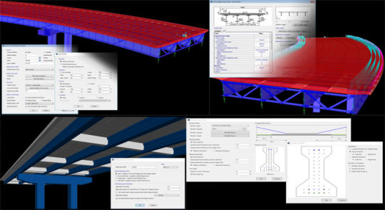
Given below, the detail and improved features of CSiBridge.
Bridge Modeler: The rapid bridge template is extended to help in explaining a more complete model along with substructure, superstructure, loading, and design criteria.
Bridge deck section superstructure loads offer the ability to effortlessly model barrier, median, sidewalk, haunch, construction, and wearing surface loads.
User specified diaphragm depths can now be stipulated for precast I-girder and concrete tee bridges Modeling.
Automated pre-stress tendon creation on the basis of tendon layouts described in precast I-girder frame section properties Analysis.
Dynamic collapse analysis facilitates an object to be eliminated throughout a nonlinear direction integration time history analysis Bridge Design.
Bridge superstructure design is included with reference to the AASHTO LRFD 2017 8th Edition code.
Read more
0 notes
Text

Computer Science Dissertation Help
Ask assignmenter.net for assistance with your manuscript, lab report, and thesis in computer science. assignmenter.net has the expertise and knowledge to help with any computer science project related to advanced interfaces, such as ambient intelligence, markerless 3D hand tracking, or advanced processor technologies, such as big data, dynamic FPGA, graph theory, HPC interconnects, mesh networks, network layer routing protocols, wireless, voice over IP, or bio-health informatics, such as clinical text mining, DNA sequencing, or formal methods, such as automated reasoning, linear and nonlinear constraints, imaging science, information management, machine learning and optimization, nanoengineering, software systems, or text mining. Assignmenter.net Dissimilarity in Dissertation in Computer Science Although the term "computer science" has many different meanings, it generally refers to the systematic study of algorithms and computers, covering theory, analysis, design, efficiency, implementation, and application. In contrast to mathematics, physics, and other comparable traditional sciences, computer science (CS) has its roots in a wide range of disciplines, such as information systems, software engineering, and computer engineering. Moreover, it necessitated the application of ideas from numerous disciplines and integrated theory, practice, general abstraction, and design-specific principles. Discrete structures, programming fundamentals, complex algorithms, programming languages, architectures and organizations, operating systems, net-centric computing, human-computer interaction, graphical and visual computing, intelligent systems, information management, software engineering, social and professional issues, computational science, and numerical methods are some of the sub-areas of computing. assignmenter.net Any type of computer science The dissertation is handled with expertise. Theoretical computer science (conceptualization, modeling, analysis, data models, levels of abstractions, objects, and operations—iteration, recursion, and induction), building or designing software systems, programming languages, testing, process methodologies (design or construction of software systems and evaluation of human-computer interaction and understanding cognitive processes), experimental computer science (theory testing and exploration), and computer simulation (investigation beyond current experimental capabilities) are among the methodologies that computer science writers are skilled in handling. While drafting the research paper or dissertation, our staff will address six key questions: what is the problem (new or known), what has been done by others to address it, what is lacking, what has been planned, and what is the anticipated result. We put a lot of effort into creating your paper, but we also make sure you can successfully defend it. You can quickly regain concentration and make substantial progress on your computer science master's or doctoral thesis with the assistance of assignmenter.net. Over 5,000 Ph.D. thesis reports have been produced to date, and we have also provided help for publishing. Our team of pros includes Ph.D. and Master's holders in computer science who can help you write your Ph.D. paper successfully step-by-step. We put a lot of effort into creating your paper, but we also make sure you can successfully defend it. Our Ph.D. professionals in computer science, who are research advisors and post-doctoral fellows with rich research experience, will guide you through every step of the process, from choosing a topic for your computer science dissertation to writing and comprehending it. They will help you successfully complete and defend your master's and doctoral dissertations in computer science.
0 notes
Text
Analysis of Lightning Surge generator Discharge Circuit

According to the working principle of the simulated surge generator used in electromagnetic compatibility tests and lightning surge generator test, combined with the commonly used 8/20 μs and 10/700 μs test waveforms in current standards, the composition and component parameters of the discharge circuit for simulating different waveforms of surge generator can be obtained through second-order differential equations and MATLAB simulation. These findings provide analytical methods and solutions for problems encountered in surge tests. Recent studies have shown that surge impulse observation devices, which combine computers and oscilloscopes, can record surge parameters in digital form. By using computer simulation software and nonlinear data fitting methods, numerical information can be transformed into corresponding simulated surge waveforms. Test personnel design surge generators based on the principle of capacitor charging and discharging, aiming to simulate overvoltage pulses generated by power system switches or lightning impulses. Understanding the composition and structure of the discharge circuit during the test process not only provides better control of the testing process, but also enables accurate judgment and in-depth analysis of problems encountered during the test. 1. Definition of Simulated Surge generator Waveform First, let us define the simulated surge generator waveform. Based on the single-pulse characteristics approximating the exponential rise and fall of a lightning pulse waveform, Bruce Godle summarized the double-exponential function of lightning current waveform. i(t)=I0k(e-at-e-βt), ( 1 ) In the formula (1), Io is the amounted to the current pulse, KA; α is attenuation before the waves Coefficient; β is the wavetail attenuation coefficient; K is the waveform correction coefficient. Similarly, voltage pulse waveforms can be represented u(t)=U0A(e-t/τ1-e-t/τ2), ( 2 ) In the formula (2), U0 is the voltage pulse amounted value, KV; A is the correction coefficient; Τ1 is a half -peak time constant; τ2 is the head time constant. Treatment of formula (1) and formula (2) can be obtained. I t)/u (t) = k (E-AT-E-βt). (3) Formula (3) is called a unit peak current/ voltage function equation. 8/20 μs The coefficient value corresponding to the wave shape of the 10/700 μS test. 2. 8/20 μS impact current generator Discharge circuit Mathematical analysis 2.1 current pulse wave micro -division equation and solution Next, we analyzed the mathematical analysis of the 8/20 μS impact current generator discharge circuit. First, we consider the differential equation of the current pulse wave and its solution. The equivalent of the impact current generator discharge circuit is shown in Figure 1. When the geometric size of the actual circuit is far less than the wavelength of the working signal, we call it a collection of total parameter circuits. The dynamic circuit composed of an independent power supply and resistance element and dynamic components, its circuit equation is a set of differential equations. The capacitance, inductance is related to the voltage and passing of the current. C -Main electric container; R -circuit impedance and wave resistance; L -circuit distribution inductance value and wave resistance. Through Kirhoff's law, we can list the relationship between the circuit and convert the differential equation of the circuit, and then solve the system's free response equation. Because the capacitor value is calculated from C × as a normalized parameter K, if the pulse current to obtain the corresponding amplitude value is to be obtained, the capacitor charging voltage must be equal to the pulse current value. However, this will increase the resistance level of charging capacitors and accelerate the aging of the capacitance. To solve this problem, in practical applications, we can appropriately increase the charging capacitor capacity through parallel capacitors and reduce the charging voltage amplitude. In addition, we can simulate through the Simulink component to obtain the discharge circuit composition and component parameters of different wave pulse waves, and to meet the standard requirements obtained by the combination of pulse waveforms. However, it should be noted that these models are established in an ideal environment, and in actual circuit design, we also need to consider the distribution parameters of components such as impedance loss, capacitance and inductors on the circuit, as well as The distributed parameters on the PEARSON coil. By fine -tuning different component parameter values, we can reach a relatively standard waveform. 3. Application of lightning surge generator: In the surge test, the application of the swarming pulse observer is very important. The surge pulse observer can record the swarming parameters in a digital form through the cooperation of the computer and oscilloscope. Through the non -linear fitting of digital information, these digital information can be converted into corresponding simulation waves. The test personnel can design the surge generator according to the principle of capacitor charging and discharge, simulation the power system switch or thunderbolt impact transients generated by transients. Through the application of surging pulse observations, test personnel can not only better grasp the test process, but also accurately judge and in -depth analysis of the problems in the test. Conclusion: (1) According to the component characteristics of the circuit (capacitive voltage, inductance current, etc.), the Cirhoff's law is used to list the circuit relationship, convert the differential equation of the circuit, and solve the system's free response equation. (2) Because the capacitance value is calculated as a normalized parameter K by the capacitor value is to obtain the pulse current with the corresponding amplitude value, the capacitor charging voltage must be equal to the pulse current value. This will increase the resistance level of the charging capacitor and accelerate the aging of the capacitance. In practical applications, because the U0C is a fixed value, it can appropriately increase the charging capacitor capacity through parallel capacitors and reduce the charging voltage amplitude. (3) Through the simulation of the Simulink component, the discharge circuit composition and component parameters of different wave pulse waves are obtained. The pulse waveform obtained by the combination meets the standard requirements. However, this is a model established in an ideal environment. In actual circuit design, it is necessary to consider the distribution parameters such as impedance loss, capacitance and inductors on the circuit, distributed parameters of the signs of the voltage of the circuit voltage, and circuit current Pearson Pearson The distributed parameters on the coil can be slightly adjusted to the values of different component to achieve a relatively standard waveform. (4) Through the inquiry of the working principle of simulated wave surges in the electromagnetic compatibility test and lightning surge generator test, and combined with the 8/20 μs and 10/700 μs test waveforms generally performed in the current standards, the second -order differential equation can be passed through the second order. Solution and Matlab calculation simulation to obtain the composition and component parameters of different waveform simulation surge generator discharge circuits. At the same time, the use of wave pulse observations can be used to observe and record, which can better grasp the test process and accurately analyze and solve the problems encountered in the test. The application of these methods and technologies will provide effective analysis methods and solutions for problems in electromagnetic compatibility tests and lightning impact tests. Lisun Instruments Limited was found by LISUN GROUP in 2003. LISUN quality system has been strictly certified by ISO9001:2015. As a CIE Membership, LISUN products are designed based on CIE, IEC and other international or national standards. All products passed CE certificate and authenticated by the third party lab. Our main products are Goniophotometer, Integrating Sphere, Spectroradiometer, Surge Generator, ESD Simulator Guns, EMI Receiver, EMC Test Equipment, Electrical Safety Tester, Environmental Chamber, Temperature Chamber, Climate Chamber, Thermal Chamber, Salt Spray Test, Dust Test Chamber, Waterproof Test, RoHS Test (EDXRF), Glow Wire Test and Needle Flame Test. Please feel free to contact us if you need any support. Tech Dep: [email protected], Cell/WhatsApp:+8615317907381 Sales Dep: [email protected], Cell/WhatsApp:+8618117273997 Read the full article
0 notes
Text
Extreme Loading: Advanced Structural Analysis with Nonlinear Software
Extreme Loading is at the forefront of structural analysis software, specializing in nonlinear structural analysis to simulate real-world scenarios. Unlike traditional methods, nonlinear analysis accounts for complex behaviors such as material nonlinearity, geometric changes, and failure prediction under extreme conditions. Whether designing for seismic resistance, blast impacts, or wind loads, Extreme Loading empowers engineers to model structures' performance under stress, ensuring safety and durability. With advanced material modeling and failure prediction, it helps optimize designs, reduce costs, and prevent catastrophic failures. Trust Extreme Loading to enhance your structural analysis, providing accurate insights for building safer, more resilient structures in an unpredictable world.
Read more about it on our blog.
extremeloading12.blogspot.com/2024/12/revolutionizing-structural-design-with.html
#structural analysis software#nonlinear structural analysis#structural engineering software programs#nonlinear structural analysis software#structure analysis software
0 notes
Text
Mastering Metal Stud Framing and Light Gauge Metal Construction
Explore the art of Metal Stud Framing and the versatility of Light Gauge Metal at SteelNetwork. Our expertise in precision construction solutions ensures durable and efficient structures. Visit Today to learn more about how we shape the future of construction with metal
#structural analysis software#wind load software#nonlinear structural analysis software#blast analysis software
0 notes
Text
Exploring Tefugen's FEA Capabilities: Harnessing Advanced Analysis Techniques
FEA is a computer application that uses numerical techniques to assess systems and structures. When subjected to thermal and structural loads, it accurately predicts how components will react. Instead of needing to construct the actual component, using a virtual computer-based model makes it easier to check the design and integrity of a component and pinpoint important areas for development. TEFUGEN offers exceptional FEA analysis and consultancy services to help with simulation-based structural and thermal evaluation of mechanical systems.
In the field of engineering design, Finite Element Analysis (FEA) has developed into a highly promising computer-aided engineering technique for modeling and analyzing structures with complex geometries and changeable material properties. It is commonly used during the design phase of a range of engineering fields, such as automotive, aerospace, power plants, and production engineering, to optimize products that increase performance.
Advantages of FEA:
Minimize the product development cost
Reduce the product lead time into the market
Accurately predict components response to load
Unlimited level of detail in the system
Analyze difficult & dangerous experiments
Easy repeatability of simulation
Linear Analysis:
The branch of FEA known as linear static analysis is most typically used to evaluate the structural and thermal performance of mechanical structures. The applied forces and displacements have a linear connection in linear static analysis. Actually, where stresses remain within the material's linear elastic range, this is relevant to all structural components. In a linear static analysis, the model's stiffness matrix is constant, and the solving time is quicker than in a nonlinear analysis of the identical model. In order to obtain an initial estimate, linear static analysis is usually used before performing a full nonlinear analysis.
Static stress analysis is likely the most common type of structural analysis using the FE technique. Stress, strain, and deformation of a component or assembly can be assessed under various load scenarios to avoid expensive failures during the design stage.
Typically, structural loads consist of one or more of the following:
Outside forces, like the clamping force in subsea connectors.
Surface loads, such as the pressure inside pressure vessels
Body pressures (gravity, acceleration such as centrifugal force in rotating machines)
Dynamic Analysis :
The phrase "dynamic FEA" describes a number of dynamic simulation methods that can be used to analyze even complicated engineering systems. Dynamic analysis is used to design and analyze potential noise and vibration issues as well as to assess the effects of transient loads. As seasoned development engineers, we rarely end our involvement in a dynamic assessment with the analytical output. We frequently collaborate with customers to identify creative solutions that are practical and beneficial from a business standpoint.
Thermal Analysis :
Thermal analysis and FEA can be used to solve heat transmission in or between solids. Convection, conduction, and radiation are a few examples of heat transport mechanisms that can be calculated. However, the analyst directly estimates convection and radiation, not the FEA software. Heat transfer analysis with FEA is normally carried out when the heat convection coefficient can be assumed to be constant along the surface of the part or when the value is precisely known. FEA-based heat transfer analysis can also be used to determine structural stresses brought on by temperature gradients in the component, including thermal expansion.
Buckling Analysis:
By the use of buckling analysis, a structure's stability under compressive loading conditions is evaluated. To verify the stability of the construction, a weight-lifting device will need to be used under compressive loads. The kind of buckling analysis employed in FE analysis is called linear buckling analysis. A static structural study must be followed by a linear buckling analysis. The results of a linear buckling analysis are buckling load factors, which are scales of the loads employed in the static structural analysis. The structure will buckle when the aforementioned level of static loading is attained, according to the simulation's results. There are countless buckling load elements that might affect a building. Every load factor has a distinct instability pattern associated with it, similar to modal analysis. The bulk of us, however, are focused on the load factor that is the lowest.
Fatigue Analysis :
A fatigue analysis is used to determine if a structure would fail after a specific number of repeated loading and unloading, or "load cycles," as opposed to replicating one load cycle as in a static analysis.
0 notes
Text
Eviews Assignment Help

EViews is a statistical software package developed by Quantitative Micro Software (QMS), which is now part of IHS Markit. EViews stands for “Econometric Views,” and it is widely used for time series analysis, econometrics, and statistical modeling. The software is particularly popular among economists, researchers, and analysts for its capabilities in handling time series data and conducting econometric analysis.
EViews includes eviews assignment writing , eviews report, eviews assignment , eviews assignment help , eviews college assignment , eviews software, eviews university assignment and many other topics.
EViews provides a user-friendly graphical interface, making it accessible to both beginners and advanced users. It offers a wide range of features, including data management, statistical analysis, forecasting, and model estimation. Some of the key functionalities of EViews include:
Data Management: EViews allows users to import various data formats, such as Excel, CSV, and databases, and organize data efficiently. Users can handle panel data, cross-sections, and time series data easily.
Time Series Analysis: EViews specializes in time series analysis and offers a rich set of tools for exploring and modeling time series data. Users can visualize time series data, test for unit roots, apply smoothing techniques, and estimate time series models like ARIMA (AutoRegressive Integrated Moving Average).
Econometric Modeling: EViews is widely used for econometric analysis. It provides tools for linear and nonlinear regression analysis, panel data analysis, limited dependent variable models (probit, logit), and many other econometric techniques.
Forecasting: The software offers various methods for time series forecasting, including exponential smoothing, ARIMA models, and others. Users can generate forecasts, evaluate forecast accuracy, and visualize forecast results.
Data Visualization: EViews allows users to create various graphical representations of data, such as scatter plots, line plots, bar charts, histograms, and more. These visualizations help in understanding patterns and relationships in the data.
Programming Support: EViews provides programming capabilities, allowing users to automate repetitive tasks and create custom procedures using EViews’ built-in programming language.
Add-ins and Extensions: EViews supports add-ins and extensions, allowing users to extend the software’s functionality and access specialized tools or models.
Due to its focus on time series and econometric analysis, EViews is commonly used in academic research, economic forecasting, financial analysis, and policy analysis. It provides a robust platform for conducting empirical studies and exploring the dynamics of economic and financial data.
Assignment on Eviews Assignment Help
Objective: The objective of this assignment is to introduce you to EViews, a popular statistical software widely used for time series analysis, econometrics, and data visualization. Through this assignment, you will learn how to import data into EViews, perform basic data analysis, and generate simple statistical outputs.
Task 1: Installation and Data Import
Download and install the latest version of EViews on your computer (if you haven’t already).
Locate a dataset in a CSV format or Excel format that you would like to analyze. It could be any dataset of your choice (e.g., stock prices, economic indicators, etc.).
Task 2: Data Exploration
Open EViews and create a new work file.
Import the dataset you chose in Task 1 into EViews.
Explore the imported data by examining the structure of the dataset, such as the number of observations, variables, and their types.
Task 3: Basic Data Analysis
Generate descriptive statistics for numerical variables in the dataset. Calculate measures such as mean, standard deviation, minimum, maximum, and quantiles.
Create a histogram for one or more numerical variables to visualize their distributions.
Calculate and interpret the correlation matrix among relevant variables in the dataset.
Task 4: Time Series Analysis
If your dataset contains time series data, create a time series plot to visualize the patterns and trends over time.
Calculate the first-order difference for a relevant variable and plot the differenced time series to observe stationarity.
Task 5: Regression Analysis
Select two or more variables from your dataset for a regression analysis.
Run a simple linear regression using EViews, and interpret the regression coefficients and goodness of fit measures (R-squared and Adjusted R-squared).
Plot the regression line along with the scatter plot of the variables used in the regression.
Task 6: Forecasting (Optional)
If your dataset is a time series, attempt a simple forecasting exercise using EViews.
Choose an appropriate forecasting method (e.g., ARIMA, exponential smoothing) and explain your choice.
Generate and interpret the forecast results, including measures of accuracy (e.g., Mean Absolute Error, Root Mean Squared Error).
Task 7: Conclusion Write a brief conclusion summarizing the insights gained from your data analysis in EViews. Discuss any patterns, trends, or relationships discovered during the analysis.
Submission Guidelines:
Prepare a well-structured report containing the tasks mentioned above.
Include relevant graphs and visualizations to support your analysis.
Provide clear explanations and interpretations of the results.
Submit your report in PDF format or any other standard document format.
Note:
In case you encounter any difficulties while using EViews, consult the software’s official documentation or seek assistance from your instructor or classmates.
This assignment aims to provide you with a foundational understanding of EViews and basic data analysis. More advanced topics and techniques can be explored in subsequent courses or assignments.
#eviews assignment#western assignment help#assignment help#assignmentexpert#assignmenthelpusa#eviews college assisgnment#eviews assignment writing
0 notes
Text
Finite Element Analyses in the Tunnel: An Overview-Iris Publishers
Authored by Buse Şeyda Hocaoğlu*

Abstract
With the development of the world and human beings’ rush to get somewhere, the need for tunneling has increased. Solutions have been made with the methods of end-to-end elements searched for a more straightforward resolution and visual thinking of tunnel projects that are complex and difficult to foresee. Thanks to these methods, geotechnical problems have been more easily detecting, and solutions have been producing in a short time. Several finite element methods have been developed in line with technology development and research. In this study, Plaxis, Flac, ABAQUS, Diana, Midas GTS NX programs, which are some of these programs, were briefly introduced, and tunnel projects solved with the mentioned programs were given
Keywords:Finite element method; Tunnel project; Plaxis 2D/3D; Flac 2D/3D; Geotechnical
Introduction
The finite element method is a numerical method that thoroughly solves mixed engineering problems. It was first developed and used in 1956 for stress analysis of aircraft bodies. It has been understood that it can also solve engineering and applied sciences problems in the following years. Over the years, the finite element method and solution techniques have developed rapidly and have become one of the best methods used to solve many problems today. The method is so popular for many engineering areas because a generic computer program can only solve any problem by changing the input data. By separating it into finite elements suitable for the structure of a problem, it implements a solution method in the form of a low energy level of internal and external forces on the obtained elements and then combining these elements. As a result, the system’s features, border conditions, sudden or continuous changes of external loads can be easily examined. It is also possible to reduce the element sizes in the constant system’s desired parts for the detailed examination of a region [1,2]. It can list the advantages of finite element methods: geometry allows complex problems to be solved, easily applicable in systems with different and complex material properties, easy to include border conditions in the fundamental equations of the system, and the use of the same model to solve many problems [2]. The disadvantages of the finite element method can be listed; found that the accuracy of the result obtained depends on the accuracy of the data, that the separation of regions requires experience to get an acceptable correct result, and that the accuracy of the result obtained is observed, and that the physical problem must be investigated well [2]. The finite element method has been used for 30 years in many engineering areas and was introduced in geotechnical engineering in 1996. The most important reason for this is that geotechnical engineering has complex issues and takes time to solve them. When used correctly, this method can provide accurate results for practical geotechnical engineering problems. A good analysis allows the engineer to understand the problem better [3]. The Finite element method can be applied to any linear-elastic medium. However, it requires many limitations for the implementation of the method in geotechnical engineering problems. In the method, material behavior is formulated by associating with changes between shape changes and total stress. In contrast, in geotechnical problems, the total tensor is decompressed into cavity water pressures and effective stresses, and material behavior is often expressed in terms of effective stresses. Most of the Geotechnical problems are interacting with the structure and the ground. Therefore, in analyzing these types of problems, it is necessary to use an intermediate surface between the structure and the soil. As a result, it is required to make changes to correctly apply the finite component method in geotechnical engineering [2]. To get a realistic result in analyzing finite elements for geotechnical engineering problems, the procedures are carried out step by step (phased loading, phased excavation). There are two benefits to ensuring that analysis can be performed in stages. First, the geometry changes at each step if the analyzes add or remove the padding. The change in geometry can be modeled by adding or removing elements from the network of end elements. Secondly, in the analysis, the ground properties change at each loading stage due to the change of stresses in the soil mass [2]. As a result of the study of finite elements in geotechnical engineering problems, parameters such as stresses, cavity water pressures, lateral and vertical movements, and groundwater flow are determined [1]. Today, programs used in finite element methods are used in many areas, such as ground mechanics, fluid mechanics, aircraft engineering, nuclear engineering, rock mechanics, etc. It can be studied by selecting the program that will give the most realistic results for problems. Examples of these programs include Plaxis 2D/3D, FLAC 2D/3D, ABAQUS, Diana, Midas GTS.
Methods
Plaxis 2D/3D
Plaxis 2D/3D, one of the finite element’s programs, is a program developed to analyze geotechnical engineering problems. The program consists of an input program, calculation program where analysis is performed, output program that graphically presents the study results, and curve program that enables the creation of the desired chart with the results obtained (Figure 1). This program is used to design projects where deformation and stabilization analyzes are needed, strain-shifting, ground structure interaction, loading conditions, carrying power, consolidation, current network, ground dynamics, and material are varied and bring real-life results [4]. According to the method of finite, a continuous environment is divided into many elements. The node points on each element have a degree of freedom. During the creation of a network of finite elements in the Plaxis program, the cells are divided into triangular elements with 6 or 15 nodes (Figure 2). Even if it takes a little more time to calculate the stresses and migration surfaces more realistically, it is better to select the 15-node element. The displacement is calculated at node points during the finite element calculation [4] (Figures 1,2).
Under the main heading Plaxisde Material Sets, the floor and structural members (Soil & Interface, anchor, Beam, and Geotextile) can be defined. The Plaxis program has several floor models, such as Mohr-Coulomb (MC), Hardening Soil (Model-HS), soft Soil Creep (Model-SSC), which are widely used for analyzing floor mechanics problems (Figure 3) [4].
Flac
FLAC is a program that uses the use of a finite element type to numerically or numerically examine the mechanical behavior of continuous media in equilibrium or progressive plastic yield. In the program, creating a network of finite differences defined by the user via elements can detect the behavior of materials such as ground and rock at the level of plastic flux. Every element behaves by the previously specified linear or non-linear stress-shape defining feature against forces applied under boundary conditions [6]. Thanks to the intermediate surface formulation in the software, the interaction between two sonly differences networks that are interconnected but are likely to divest or slide along a surface, such as a fault structure, can also be modeled. Hydrostatic pressure used in liquefies research or design of dams is carried out by applying fluid mechanics formulation. Structural elements are used to model entities such as anchors and flooring nails. In addition to all these, it is possible to perform realistic modeling with this software by applying static and dynamic boundary conditions. Although FLAC has been developed for Geotechnical engineering applications, it is also widely used in many research areas such as mining engineering, underground structures, and rock mechanics (Figure 4) [6].
The use of the FLAC finite element program in some engineering applications is as follows:
1. Calculation of transport capacities and deformations according to ground and loading conditions in the design of slope and foundations.
2. In the ground structures, calculate the safety coefficient in the stability analysis of fillers and slope.
3. Assessing the fault structure and impact of the interest structure in mining research projects.
4. Design of floor anchorages, rock bullion, ground nail, and support systems in geotechnical problems.
5. Examination of the dynamic effects that will occur resulting from vibration and explosion in tunnel and mine excavations.
6. performing seismic analysis of structures in the design of earth filling dams.
The solution of the Flac finite elements method consists of the three-step approach given below. The solution method for FLAC finite components consists of the following three-stage process. First, the finite differences phase, a limited time, and the change over field linear default variables are estimated by the time and finite differences of the first degree. Second, the model’s deposition phase: An equivalent environment replaces the continuous environment by a deposition. In the new environment, all forces are assumed to be gathered at the nodes of a three-dimensional network. Third, the dynamic solution phase is used to access the system’s balanced state, whose inertia terms in motion equations are analyzed as numeric agents [6].
Abaqus
Abaqus is a finite element method that works through a detailed analysis of engineering problems by creating realistic computeraided models (Figure 5).
It offers the ability to analyze linear and nonlinear projects that are difficult to solve due to the different material models and finite element types involved [8]. The program consists of five essential software: Standard, Explicit, CFD, Electromagnetic, and CAE. ABAQUS/Standard uses solution technology, ideal for static and low-speed dynamic events where highly sensitive stress solutions are critical. Within a single simulation, it is possible to analyze a model in both the frequency and time zone. Standard is closed finite elements software that can perform static and dynamic analyzes. Their solution uses advanced material and element features. It can also perform acoustic and associated doubleacting analyzes, and the plastic injection can be used in conjunction with various programs for mold analysis results [8]. Abaqus/Explicit, a particular purpose finite element analyzer that uses an open integration scheme to solve many complex contacts, nonlinear systems under transient loads. At the same time, automotive is particularly suitable for simulating short transient dynamic events such as collision capability and ballistic impact. It is a handy software for simulating semi-static events, such as handling nonlinear behavior and the rounding of hot metal effectively.
Collision tests can be used for dropping tests and resolution of strain problems [8]. Abaqus/CFD, it is the software that Abaqus offers to solve computational fluid dynamics problems. It can solve nonlinear fluid-structural and fluid-thermal problems. Real results are achieved when used in nonlinear structural-flow and heat- flow applications [8]. Abaqus/Electromagnetic offers an advanced computational solution of electromagnetic problems [8]. Abaqus/ CAE is a software used for both the modeling of mechanical components and its analysis and visualizes the analysis results. Thanks to its intuitive interface, it is user-friendly in modeling, research, and result visualization [8].
Diana
Chan in 1988, designed for dynamic, static, and consolidation analysis of geomechanical problems. It is a 2-dimensional element program that contains plane deformation and asymmetric analysis. The program has five ground models. It can be rank these models as a linear elastic model, Coulomb changing with average effective environmental pressure, a general elastic model with friction envelope, elastic-full plastic Mohr-Coulomb, original glass clay Pastor-Zienkiewicz Mark-III models. The DIANA program requires four input files for each finite element analysis to be performed. These input files consist of mesh, data, introduction, and earthquake files. Running an analysis requires these input files to be created in a specific order [10]. The network file defines the geometry of the finite element network to be used in the analysis. The geometry of the defined floor model is divided into smaller regions, creating a finite element net. The input file ‘DYNMGEN’ is used to prepare the network file [10]. The data file contains control data to be used to perform finite element analysis. All technical information about finite element analysis is stored in this file [10]. The Initial file creates the initial conditions for finite element analysis. This file’s data contains the initial speed, start time, start displacement, maximum displacement norm, earthquake status, initial acceleration, and internal parameters of the ground model. The ‘DYNINT’ input file is used to prepare the initial data file [10]. The earthquake file is the last input file required for finite element analysis. The important aspect to be considered in preparing this input file required for dynamic analysis is the type of earthquake and the scale factor. For dynamic analysis, the desired load transaction type and transaction scale must be created in the ‘DYNEQK’ input file and encoded in the scale factor data file [10].
Midas GTS NX
MIDAS GTS NX is an important method of finite elements for geotechnical and tunnel analysis systems. It can model geological problems that are difficult to model with advanced technology [11]. In Midas GTS NX, geometry is modeled in 2 shapes. The first is that geometry is drawn in 2D or transferred from drawing programs. A network of 2D finite elements is then created and offset to the 3rd dimension, resulting in a model of 3D finite elements. This method may not be available for complex geometries. The other method is to create 3D geometric objects by giving dimensions 3rd dimension in 2 sizes or transferred using the command “extrude” [12].
Examples Using the Finite Element Method
Tunnel example with Plaxis Program
In this tunnel project application, the Plaxis 2D program, one of the finite programs, has calculated deformations that can be caused by the passage of tunnels. In line with these deformations, ground improvement methods have been implemented. The Plaxis program is selected for this application because complex boundary conditions and nonlinear material behavior allow systematic programming in solving challenging and complex problems such as non-homogeneous materials. 6 different cases have been explored in this application. In the first application, the whole floor is assumed to be clay, and the tunnel is added. (Figure 6). In the second application, tunneling is performed in the clay and sandy variable ground profile with different ground parameters (Figure 7). The deformation of the floor surface and the deformation of the tunnel covering have the same value and have increased by 50,92 mm. In the third application, he implemented a building load without improving the previous project (Figure 8). The deformation of the floor surface has increased to 87,41 mm. Due to the tunnel covering’s building load; the deformation value has risen to 52, 57 mm. Improved soil with geotextiles and sealants before applying building load in the fourth application (Figures 6-9).
Due to the optimization, the deformation of the floor surface has been retightened to 67,49 mm. The deformation value in the tunnel covering is close to the previous example and has dropped to 51,71 mm. A 2 m thick floor injection method is implemented as an enhancement (Figure 10). As a result of this optimization, the soil surface’s deformation has been retightened from 67,49 mm to 58,62 mm. The deformation value in the tunnel lining is 52.54 mm. The sixth application assumes that a 5-story building with two basements is built on the ground, and the deformation value in the tunnel coating is 50.51 mm (Figures 10,11).
As a result of these examples, finite element programs must be analyzed to ensure that new structures built after tunnel construction are constructed without damaging the tunnel and existing structures. A non-damaged construction must be carried out by determining suitable solutions to the problems that will arise. Before applying a building load, improvements can be made to the characteristics of the floor, thus setting the seating values on the floor surface to lower values. It is important to maintain the ground during tunnel construction and select two to maintain the tunnel’s stability. The groundwater check must be carried out from the start of the project. The tunnel is to be built must be checked that it will not damage structures around it [13].
Tunnel example with FLAC 3D Program
Pressed floors can cause many problems, such as the collapse of supports due to heavy load, groundwater, excessive closure of pile profiles, or destruction of tunnel support. Therefore, before tunneling on such floors, the type and severity of the jamming that may occur should be investigated in advance. A specific formula produced by Hoek-Brown is used to predict the possibility of jamming and to analyze the jam. Flac 3D, Finite elements program, was used to determine the Hoek-Brown criteria parameters to be taken into account in the analysis of trapped floors in this application. For these studies, four Hoek-Brown input parameters are considered and modeled mainly: Rock mass parameters GSI (geological strength index), UCS (single-axis press strength), MI (Hoek material constant), and H (covering thickness). Code (FISH code) has been written by the Hoek-Brown criteria, as Flac3D is based on Mohr-Coulomb criteria. Numerical modeling results using GSI, H, UCS, and mi variables according to Hoek and Brown defeat criteria are presented separately as deformation contours and plastic zone contours. Deformation contours have been found to have a significant reduction in deformation contours around the tunnel as the GSI value increases from three-dimensional numeric models with different GSI values (Figure 12). In line with the results obtained by giving different tunnel cover thickness values, it was determined that the deformations around the tunnel increased rapidly as H increased (Figure 13). As a result of the deformation contours for the different mİ values from the three-dimensional numeric models, the mİ value has increased. In contrast, the deformation values have been found to have very little reduction than the other parameters (Figure 14). Thus, it is understood that the effect of mİ value on the potential for compression is not an important parameter. A significant reduction in deformation around the tunnel has been identified as the UCS value increases about deformation contours from three-dimensional numerical models using different single axis thrust strength values (Figures 12-15).
As a result of different GSI values, plastic zone contours decreased significantly in the thickness of the plastic area around the tunnel as the values increased (Figure 16). Using different cover thicknesses, it was determined that the value of plastic zone thickness increased as it increased (Figure 17). Using another mi value, it was determined that the plastic zone thickness values decreased due to the increase (Figure 18). While a change in the plastic zone size was observed with the increase in MI value, it was determined that this determined change MI parameter was not a useful parameter on the plastic zone. Using different single axis thrust strength values has determined that the plastic zone thickness around the tunnel decreases as the UCS value increases (Figures 16-19).
In parallel with the result of the plastic region radius, analyzes, and deformation analysis, the study’s parameters revealed that GSI, UCS, and H were the most influential parameters. It should be considered that the effect of the MI parameter will also change when the fixed parameters are changed, even though the impact of the MI parameter is low [14].
Result
As a result of developing technologies and research, existing programs have been designed and provided ease of solution to many engineering problems. The programs in which the method of finite elements was applied increased over time. In this way, almost every engineering branch has used appropriate programs for its problems. Many complex and time-long issues have been solved in fewer time thanks to these programs. Questions are broken down into pieces and solved in more detail, resulting in more realistic results. The development of programs and the introduction of 3D solutions have made it easier to understand problems and solutions. This makes tunnel projects easier to solve, and errors can be detected. Problems encountered during the opening phase of tunnels have been quickly resolved, and necessary improvements have been made. As technology evolves and people seek more realistic results, the finite element methods will continue to grow and develop.
Read More...FullText
For more about Iris Publishers slide share please click on https://www.slideshare.net/IrisPublishers/iris-publishers
For more articles in Current Trends in Civil & Structural Engineering (CTCSE) Please click on https://irispublishers.com/ctcse/
#iris publishers llc#Iris Publishers#Current Trends in Civil & Structural Engineering#Finite Element Analyses
1 note
·
View note
Text
Iris Publishers - Global Journal of Engineering Sciences (GJES)
Artificial Neural Networks and Hopfield Type Modeling
Authored by Haydar Akca

From the mathematical point of view, an artificial neural network corresponds to a non- linear transformation of some inputs into certain outputs. Many types of neural networks have been proposed and studied in the literature and the Hopfield-type network has be- come an important one due to its potential for applications in various fields of daily life.
A neural network is a network that performs computational tasks such as associative memory, pattern recognition, optimization, model identification, signal processing, etc. on a given pattern via interaction between a number of interconnected units characterized by simple functions. From the mathematical point of view, an artificial neural network corresponds to a nonlinear transformation of some inputs into certain outputs. There are a number of terminologies commonly used for describing neural networks. Neural networks can be characterized by an architecture or topology, node characteristics, and a learning mechanism [1]. The interconnection topology consists of a set of processing elements arranged in a particular fashion. The processing elements are connected by links and have weights associated with them. Each processing elements is associated with:
• A state of activation (state variable)
• An output function (transfer function)
• A propagation rule for transfer of activation between processing elements
• An activation rule, which determines the new state of activation of a processing element from its inputs weight associated with the inputs, and current activation.
Neural networks may also be classified based on the type of input, which is either binary or continuous valued, or whether the networks are trained with or without supervision. There are many different types of network structures, but the main types are feed-forward networks and recurrent networks. Feed-forward networks have unidirectional links, usually from input layers to output layers, and there are no cycles or feedback connections. In recurrent networks, links can form arbitrary topologies and there may be arbitrary feed- back connections. Recurrent neural networks have been very successful in time series prediction. Hopfield networks are a special case of recurrent networks. These networks have feedback connections, have no hidden layers, and the weight matrix is symmetric.
Neural networks are analytic techniques capable of predicting new observations from other observations after executing a process of so-called learning from existing data. Neural network techniques can also be used as a component of analysis designed to build explanatory models. Now there is neural network software that uses sophisticated algorithms directly contributing to the model building process.
In 1943, neuro physiologist Warren McCulloch and mathematician Walter Pitts [2] wrote a paper on how neurons might work. In order to describe how neurons in the brain might work, they modeled a simple neural network using electrical circuits. As computers be- came more advanced in the 1950’s, it was possible to simulate a hypothetical neural net- work. In 1982, John Hopfield presented a paper [3]. His approach was to create more useful machines by using bidirectional lines. The model proposed by Hopfield, also known as Hopfield’s graded response neural network, is based on an analogue circuit consisting of capacitors, resistors and amplifiers. Previously, the connections between neurons was only one way. At the same years, scientist introduced a “Hybrid network” with multiple layers, each layer using a different problem-solving strategy.
Now, neural networks are used in several applications. The fundamental idea behind the nature of neural networks is that if it works in nature, it must be able to work in computers. The future of neural networks, though, lies in the development of hardware. Research that concentrates on developing neural networks is relatively slow. Due to the limitations of processors, neural networks take weeks to learn. Nowadays trying to create what is called a “silicon compiler”, “organic compiler” to generate a specific type of integrated circuit that is optimized for the application of neural networks. Digital, analog, and optical chips are the different types of chips being developed.
The brain manages to perform extremely complex tasks. The brain is principally com- posed of about 10 billion neurons, each connected to about 10,000 other neurons. Each neuronal cell bodies (soma) are connect with the input and output channels (dendrites and axons). Each neuron receives electrochemical inputs from other neurons at the dendrites. If the sum of these electrical inputs is sufficiently powerful to activate the neuron, it transmits an electrochemical signal along the axon, and passes this signal to the other neurons whose dendrites are attached at any of the axon terminals. These attached neurons may then fire. It is important to note that a neuron fires only if the total signal received at the cell body exceeds a certain level. The neuron either fires or it doesn’t, there aren’t different grades of firing. So, our entire brain is composed of these interconnected electro- chemical transmitting neurons. This is the model on which artificial neural networks are based. Thus for, artificial neural networks haven’t even come close to modeling the complexity of the brain, but they have shown to be good at problems which are easy for a human but difficult for a traditional computer, such as image recognition and predictions based on past knowledge.
Fundamental difference between traditional computers and artificial neural networks is the way in which they function. One of the major advantages of the neural network is its ability to do many things at once. With traditional computers, processing is sequential– one task, then the next, then the next, and so on. While computers function logically with a set of rules and calculations, artificial neural networks can function via Equation, pictures, and concepts. Based upon the way they function, traditional computers have to learn by rules, while artificial neural networks learn by example, by doing something and then learning from it.
Hopfield neural networks have found applications in a broad range of disciplines [3-5] and have been studied both in the continuous and discrete time cases by many researchers. Most neural networks can be classified as either continuous or discrete. In spite of this broad classification, there are many real-world systems and natural processes that behave in a piecewise continuous style interlaced with instantaneous and abrupt changes (impulses). Periodic dynamics of the Hopfield neural networks is one of the realistic and attractive modellings for the researchers. Hopfield networks are a special case of recurrent networks. These networks have feedback connections, have no hidden layers, and the weight matrix is symmetric. These networks are most appropriate when the input can be represented in exact binary form. Signal transmission between the neurons causes time delays. Therefore, the dynamics of Hopfield neural networks with discrete or distributed delays has a fundamental concern. Many neural networks today use less than 100 neurons and only need occasional training. In these situations, software simulation is usually found sufficient. Expected and optimistic development on all current neural network’s technologies will improve in very near future and researchers develop better methods and network architectures.
In the present paper, we briefly summarized historical background as well as developments of the artificial neural networks and present recent formulations of the continuous and discrete counterpart of a class of Hopfield-type neural networks modeling using functional differential equations in the presence of delay, periodicity, impulses and finite distributed delays. Combining some ideas of [4,6-10] and [11], we obtain a sufficient condition for the existence and global exponential stability of a unique periodic solution of the discrete system considered.
Artificial Neural Networks (ANN)
An artificial neural network (ANN) is an information processing paradigm that is in- spired by the way biological nervous systems, such as the brain, process information sees more details [12] and references given therein. The key element of this paradigm is the novel structure of the information processing system. It is composed of a large number of highly interconnected processing elements (neurons) working in unison to solve specific problems. ANNs, like people, learn by example. An ANN is configured for a specific application, such as pattern recognition or data classification, through a learning process. Learning in biological systems involves adjustments to the synaptic connections that exist between the neurons. This is true of ANNs as well.
The first artificial neuron was produced in 1943 by the neurophysiologist Warren McCulloch and the logician Walter Pitts [2]. But the technology available at that time did not allow them to do too much. Neural networks process information in a similar way the human brain does. The network is composed of a large number of highly interconnected processing elements (neurons) working in parallel to solve a specific problem. Neural net- works learn by example. Much is still unknown about how the brain trains itself to process information, so theories abound. An artificial neuron is a device with many inputs and one output (Figure 1). The neuron has two modes of operation; the training mode and the using mode. In the training mode, the neuron can be trained to fire (or not), for particular input patterns. In the using mode, when a taught input pattern is detected at the input, its associated output becomes the current output. If the input pattern does not belong in the taught list of input patterns, the firing rule is used to determine whether to fire or not. An important application of neural networks is pattern recognition. Pattern recognition can be implemented by using a feed-forward (Figure 2) neural network that has been trained accordingly. During training, the network is trained to associate outputs with in- put patterns. When the network is used, it identifies the input pattern and tries to output the associated output pattern. The power of neural networks comes to life when a pattern that has no output associated with it, is given as an input. In this case, the network gives the output that corresponds to a taught input pattern that is least different from the given pat- tern. Hopfield-type neural networks are mainly applied either as associative memories or as optimization solvers. In both applications, the stability of the networks is prerequisite. The equilibrium points (stable states) of networks characterize all possible optimal solutions of the optimization problem, and stability of the network’s grantee the convergence to the optimal solutions. Therefore, the stability is fundamental for the network design. As a result of this fact the stability analysis of the Hopfield-type networks has received extensive attention from the many researchers, [4,6-9,11,13] and references given therein. The above neuron does not do anything that conventional computers do not already do. A more sophisticated neuron (Figure 3) is the McCulloch and Pitts model (MCP). The difference from the previous model is that the inputs are ‘weighted’, the effect that each input has at decision making is dependent on the weight of the particular input. The weight of an input is a number which when multiplied with the input gives the weighted input. These weighted inputs are then added together and if they exceed a pre-set threshold value, the neuron fires. In any other case the neuron does not fire. In mathematical terms, the neuron fires if and only if
X1W1 + X22 + X3W3 + …. > T,
where Wi, i = 1, 2, . . ., are weights, Xi, i = 1, 2, . . ., inputs, and T a threshold. The addition of input weights and of the threshold makes this neuron a very flexible and powerful one. The MCP neuron has the ability to adapt to a particular situation by changing its weights and/or threshold. Various algorithms exist that cause the neuron to ‘adapt’; the most used ones are the Delta rule and the back-error propagation. The former is used in feed-forward networks and the latter in feedback networks.
Neural networks have wide applicability to real world business problems. In fact, they have already been successfully applied in many industries. Since neural networks are best at identifying patterns or trends in data, they are well suited for prediction or forecasting needs including sales forecasting, industrial process control, customer research, data validation, risk management, target marketing.
ANN are also used in the following specific paradigms: recognition of speakers in communications; diagnosis of hepatitis; recovery of telecommunications from faulty software; interpretation of multi-meaning Chinese words; undersea mine detection; texture analysis; three-dimensional object recognition; hand-written word recognition; and facial recognition.
To read more about this article https://irispublishers.com/gjes/fulltext/artificial-neural-networks-and-hopfield.ID.000601.php
Indexing List of Iris Publishers: https://medium.com/@irispublishers/what-is-the-indexing-list-of-iris-publishers-4ace353e4eee
Iris publishers google scholar citations: https://scholar.google.co.in/scholar?hl=en&as_sdt=0%2C5&q=irispublishers&btnG=
1 note
·
View note