
Don't wanna be here? Send us removal request.
Statistics
We looked inside some of the posts by vavaclasses and here's what we found interesting.
Average Info
Notes Per Post
0
Likes Per Post
0
Reblog Per Post
0
Reply Per Post
0
Time Between Posts
8 days
Number of Posts By Type
Text
17
Last Seen Tumblr Blogs


Fun Fact
28.6 is the average number of monthly visits per US mobile user.
Text
National Doctor's Day: A Tribute and Motivation for Future Doctors
Introduction:
Every year on July 1st, India celebrates National Doctor’s Day to honor the invaluable contribution of doctors in saving lives and serving humanity. For NEET aspirants and students preparing for medical entrance exams, this day is more than a celebration — it is a source of deep motivation and purpose. At VAVA Classes, we take this opportunity to inspire the next generation of doctors to dream bigger and serve better.

Why is National Doctor's Day Celebrated?
Honoring Dr. Bidhan Chandra Roy:
National Doctor’s Day in India commemorates the birth and death anniversary of Dr. B.C. Roy, a renowned physician, freedom fighter, and former Chief Minister of West Bengal. His dedication to the field of medicine and public service is a beacon for medical aspirants across the country.
What Makes This Day Special for NEET Aspirants?
It’s a Day of Purpose
For students aiming for a seat in MBBS or other medical programs through NEET (National Eligibility cum Entrance Test), this day is a powerful reminder of the noble profession they aspire to join.
Motivation to Push Harder
Hearing stories of doctors who once were students battling textbooks and mock tests can boost your motivation, especially during times of stress or burnout.
Reinforcing the Dream
Doctor’s Day reinforces the reason behind those long study hours — to serve, to heal, and to make a difference.
How Can NEET Aspirants Celebrate Doctor's Day?
1. Learn from Real Stories
Watch documentaries, read biographies, or attend webinars where doctors share their journeys. These real-life experiences can guide your own path.
2. Recommit to Your NEET Goal
Take this day to set a new milestone in your preparation — revise a difficult topic, take a mock test, or organize your study plan.
3. Thank the Doctors Around You
If you or your family have ever been helped by a doctor, a small thank-you note or call can make their day.
4. Join a Special Session at VAVA Classes
At VAVA Classes, we often host motivational webinars and guest talks from doctors to help NEET aspirants see the real-world impact of their future profession.
Lessons from Doctor’s Day for Future Medical Students
Discipline and Dedication
Success in NEET and in medicine requires unwavering focus — something every successful doctor embodies.
Compassion is Key
Medicine is not just about knowledge but empathy. This value must be built during the student phase itself.
Conclusion
National Doctor’s Day is not just about honoring existing doctors — it’s about encouraging future ones too. If you’re a NEET aspirant, let this day ignite a stronger passion for your dream. At VAVA Classes, we believe that every doctor starts with a dream, and every dream needs the right guidance. Let us walk this journey with you — from books to white coats.
👉 Join VAVA Classes Today and take your NEET preparation to the next level. Let's make your dream of becoming a doctor come true!
📞 Call: 9090961010
🌐 Visit: www.vavaclasses.com
#National Doctor's Day 2025#NEET preparation tips#Inspiration for NEET aspirants#Doctor’s Day motivation#Medical entrance exam coaching#How to prepare for NEET exam
0 notes
Text
Detailed Study Notes on Class 12 Chemistry: Proteins
Introduction:
Proteins are vital biological macromolecules essential for life. In Class 12 Chemistry (Chapter: Biomolecules), understanding proteins includes their structure, types, and functions. These notes help you grasp the key concepts easily for board exams and competitive preparation like NEET and JEE.

What Are Proteins?
Proteins are large, complex molecules made up of amino acids joined by peptide bonds. They play critical roles in almost all biological processes. Chemically, proteins are polymers of α-amino acids.
Amino Acids – Building Blocks of Proteins
Structure of α-Amino Acids: Each amino acid has a central α-carbon, an amino group (–NH₂), a carboxylic group (–COOH), a hydrogen atom, and a variable R group. General formula: NH₂–CH(R)–COOH Classification: - Essential Amino Acids (e.g., Valine, Leucine) - Non-Essential Amino Acids (e.g., Glycine, Alanine)
Formation of Peptides and Proteins
Peptide Bond: Formed when –COOH of one amino acid reacts with –NH₂ of another, releasing water. Types: - Dipeptide: 2 amino acids - Tripeptide: 3 amino acids - Polypeptide: Many amino acids - Protein: More than ~50 amino acids in a specific 3D structure
Structure of Proteins
1. Primary Structure: Linear sequence of amino acids. 2. Secondary Structure: α-Helix and β-Pleated Sheet (hydrogen bonds). 3. Tertiary Structure: 3D shape formed by R-group interactions. 4. Quaternary Structure: Multiple polypeptide chains (e.g., Hemoglobin).
Classification of Proteins
By Composition: - Simple Proteins: Only amino acids - Conjugated Proteins: With non-protein parts By Function: - Structural: Keratin, Collagen - Enzymatic: Pepsin, Amylase - Transport: Hemoglobin - Hormonal: Insulin
Denaturation of Proteins
Loss of structure and biological activity due to temperature, pH, or chemicals. Example: Cooking an egg – Albumin protein coagulates.
Functions of Proteins
- Structural: Build cells and tissues - Enzymatic: Catalyze reactions - Transport: Carry substances - Regulatory: Hormones - Protective: Antibodies
Protein Tests (Class 12 Practical Relevance)
Biuret Test: Purple color indicates proteins. Xanthoproteic Test: Yellow color shows aromatic amino acids.
Important Protein Examples for Board Exams
Hemoglobin – Oxygen transport Insulin – Blood sugar regulation Albumin – Osmotic pressure control Pepsin – Protein digestion
Conclusion
Understanding proteins in Class 12 Chemistry is crucial for exams and future studies. Focus on structure, classification, and functions. Use diagrams and tables for clarity.
#vavaclasses#11thclass#science#biology#chemistry#physics#class 12#iit jee#neet#class 11 physics notes
0 notes
Text
Carbohydrates Class 12 Chemistry Notes- Biomolecules Chapter Explained
Introduction to Carbohydrates
Carbohydrates are the most abundant organic compounds found in nature and are vital for life. They serve as a primary source of energy for living organisms. Chemically, carbohydrates are polyhydroxy aldehydes or ketones or compounds that yield them on hydrolysis. The general formula is Cn(H2O)n.

Classification of Carbohydrates
1. Monosaccharides
• Simplest form of carbohydrates. • Cannot be hydrolyzed further. • General formula: CnH2nOn • Examples: Glucose, Fructose
2. Oligosaccharides
• Contain 2–10 monosaccharide units. • Most important oligosaccharide: Disaccharides • Examples: Sucrose (Glucose + Fructose), Lactose (Glucose + Galactose), Maltose (Glucose + Glucose)
3. Polysaccharides
• Long chains of monosaccharide units. • Not sweet, insoluble in water. • Examples: Starch, Cellulose, Glycogen
Structure and Function of Monosaccharides
Monosaccharides are further classified based on: - Number of carbon atoms: Trioses, Tetroses, Pentoses, Hexoses - Functional group: • Aldoses (with –CHO group) • Ketoses (with –CO group) Glucose is an aldohexose with the formula C6H12O6. It exists in two cyclic forms: α-glucose and β-glucose.
Reducing and Non-Reducing Sugars
Reducing Sugars
• Can reduce Fehling’s or Tollen’s reagent. • Contain free aldehyde or ketone group. • Examples: Glucose, Maltose, Lactose
Non-Reducing Sugars
• Do not have a free –CHO or –CO group. • Example: Sucrose
Properties of Glucose
• Sweet, soluble in water • Undergoes oxidation and reduction • Does not react with Schiff’s reagent • Exists as α- and β- anomers in solution
Polysaccharides in Biological Systems
Starch
• Plant storage carbohydrate • Made of amylose and amylopectin
Glycogen
• Animal storage carbohydrate • Similar to amylopectin but more branched
Cellulose
• Structural polysaccharide in plants • Cannot be digested by humans
Tests for Carbohydrates
1. Molisch’s Test
• General test for carbohydrates (violet ring formation)
2. Benedict’s Test
• Detects reducing sugars (brick red precipitate)
3. Fehling’s Test
• Another test for reducing sugars (red ppt. of Cu2O)
Importance of Carbohydrates:
• Source of energy: 1 gram = 4 kcal • Storage: Glycogen in animals, starch in plants • Structural role: Cellulose in plant cell walls • Component of biomolecules: DNA, RNA (ribose, deoxyribose)
Conclusion
Carbohydrates are crucial biomolecules that play multiple roles in metabolism and structure. Understanding their classification, structure, and functions provides a strong foundation in organic chemistry and biology. In exams, focus on glucose structure, disaccharide linkages, and polysaccharide functions for scoring high.
#vavaclasses#11thclass#science#biology#chemistry#physics#class 12#iit jee#neet#class 11 physics notes
0 notes
Text
Integration by Parts – Class 12 Mathematics Notes
Introduction:
Integration by Parts is a crucial technique in integral calculus, especially useful when dealing with the integration of the product of two functions. It is derived from the product rule of differentiation and helps solve complex integrals that cannot be integrated directly. Understanding this method thoroughly will aid in solving various problems in CBSE Class 12 board exams and competitive exams like JEE Main.

Formula for Integration by Parts:
If u = f(x) and v = g(x), then:
∫ u·v dx = u ∫v dx - ∫ (du/dx · ∫v dx) dx
Or simply,
∫ u·v dx = uv - ∫ v·(du/dx) dx
Choosing u and v – ILATE Rule:
To select which function to differentiate and which to integrate, use the ILATE rule:
I: Inverse Trigonometric functions L: Logarithmic functions A: Algebraic functions T: Trigonometric functions E: Exponential functions
Solved Examples of Integration by Parts:
Evaluate ∫ x · e^x dx
Let u = x (Algebraic), dv = e^x dx Then, du = dx, and v = ∫ e^x dx = e^x Apply the formula: ∫ x·e^x dx = x·e^x - ∫ e^x dx = x·e^x - e^x + C Answer: ∫ x·e^x dx = e^x(x - 1) + C
Evaluate ∫ ln x dx
Let u = ln x, dv = dx Then, du = (1/x) dx, v = ∫ dx = x Apply the formula: ∫ ln x dx = x·ln x - ∫ x·(1/x) dx = x·ln x - ∫ 1 dx = x·ln x - x + C Answer: ∫ ln x dx = x(ln x - 1) + C
Evaluate ∫ x · sin x dx
Let u = x, dv = sin x dx Then, du = dx, v = ∫ sin x dx = -cos x Apply the formula: ∫ x·sin x dx = -x·cos x + ∫ cos x dx = -x·cos x + sin x + C Answer: ∫ x·sin x dx = -x·cos x + sin x + C
Special Cases and Tips:
Some integrals may require repeated application of the formula. For example: ∫ x^2 e^x dx
Practice Questions
1. ∫ x · cos x dx 2. ∫ x · ln x dx 3. ∫ x^2 · e^x dx 4. ∫ arctan x dx 5. ∫ ln x dx
Conclusion:
Integration by Parts is a powerful technique in calculus, especially when dealing with products of functions. Mastery of the ILATE rule and regular practice of varied problems ensures confidence and accuracy in the exams.
#vavaclasses#11thclass#science#biology#chemistry#physics#class 12#iit jee#neet#class 11 physics notes#Integration by Parts Class 12#Integration by Parts formula#Integration by Parts examples with solutions#Class 12 Maths Chapter Integrals#Integration methods for Class 12#CBSE Class 12 Integration notes
0 notes
Text
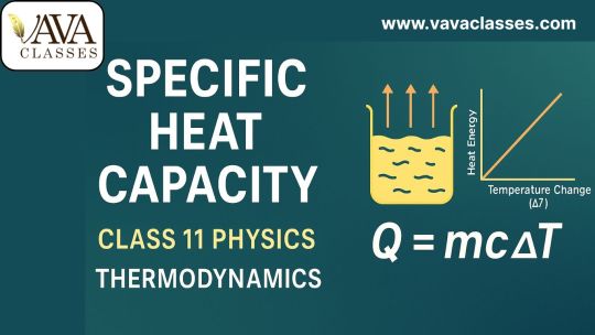
Specific Heat Capacity – Class 11 Physics Notes
Introduction:
Thermodynamics is a vital part of Class 11 Physics that deals with heat, energy, and their transformation. One of the essential concepts in this chapter is Specific Heat Capacity. Understanding this topic helps explain how substances respond to heat and why different materials heat up or cool down at different rates.
What is Specific Heat Capacity?
Specific Heat Capacity (c) is defined as the amount of heat required to raise the temperature of one kilogram of a substance by one degree Celsius (or 1 Kelvin).
Formula: Q = mcΔT
Where: - Q = heat energy supplied (in joules) - m = mass of the substance (in kg) - c = specific heat capacity (in J/kg·K) - ΔT = change in temperature (in °C or K)
Unit and Dimensions of Specific Heat Capacity:
- SI Unit: Joule per kilogram per Kelvin (J/kg·K) - CGS Unit: Calorie per gram per degree Celsius (cal/g·°C) - Dimensions: [L² T⁻² Θ⁻¹]
Types of Heat Capacities:
1. Specific Heat at Constant Volume (Cv)
Heat required to raise the temperature at constant volume. Relevant for gases in rigid containers.
2. Specific Heat at Constant Pressure (Cp)
Heat required to raise the temperature at constant pressure. Higher than Cv due to additional work done during expansion.
Relationship for ideal gases: Cp - Cv = R
Molar Specific Heat Capacity:
The heat capacity of 1 mole of a substance. Units: J/mol·K
Factors Affecting Specific Heat Capacity:
1. Nature of the Material
Metals have low specific heat, water has high specific heat.
2. Phase of Substance
Solids, liquids, and gases have different specific heats.
3. Temperature Range
Specific heat can vary with temperature.
Applications of Specific Heat Capacity:
- Cooking utensils - Climate control - Automobile cooling systems - Calorimetry
Worked Examples:
Example 1
How much heat is needed to raise the temperature of 2 kg of water from 25°C to 75°C? Given: c = 4186 J/kg·K
Q = mcΔT = 2 × 4186 × (75 - 25) = 418600 J
Example 2
A 500 g metal requires 2000 J to raise its temperature by 10°C. Find its specific heat.
c = Q / (mΔT) = 2000 / (0.5 × 10) = 400 J/kg·K
Experimental Determination (Calorimetry Method)
Principle of Calorimetry:
Heat lost = Heat gained
Procedure:
Use a calorimeter, heat a substance, place it in the calorimeter, measure equilibrium temperature, and use the equation to solve.
Conclusion:
Specific Heat Capacity is a crucial thermodynamic concept that helps us understand the thermal behavior of different materials. It forms the foundation for real-world applications such as climate science, engineering, and even daily cooking.
#vavaclasses#11thclass#science#biology#chemistry#physics#class 12#iit jee#neet#class 11 physics notes
0 notes
Text
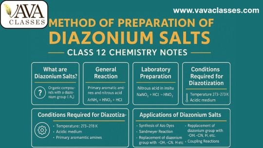
Method of Preparation of Diazonium Salts – Class 12 Chemistry Notes
Introduction:
Diazonium salts form an important category of organic compounds that are widely used in organic synthesis, especially in the manufacture of azo dyes, pharmaceuticals, and aromatic derivatives. These compounds are prepared primarily from aromatic amines and are characterized by the presence of the functional group –N₂⁺X⁻. In Class 12 Chemistry, the topic is covered under the chapter “Amines”, and it often carries significant weightage in CBSE Board exams and entrance exams like NEET and JEE.
What are Diazonium Salts?
Diazonium salts are organic compounds that contain a diazonium group (–N₂⁺) attached to an aryl group. The general formula is ArN₂⁺X⁻, where: - Ar = Aromatic group (usually derived from benzene) - X⁻ = Anion like Cl⁻, Br⁻, NO₃⁻, HSO��⁻, etc.
Example: Benzenediazonium chloride (C₆H₅N₂⁺Cl⁻)
General Method of Preparation of Diazonium Salts
Diazonium salts are prepared by a chemical reaction known as diazotization, which involves the reaction of primary aromatic amines with nitrous acid (HNO₂) in an acidic medium under cold conditions (0–5°C).
General Reaction: ArNH₂ + HNO₂ + HX → ArN₂⁺X⁻ + 2H₂O
Example using Aniline: C₆H₅NH₂ + HNO₂ + HCl → C₆H₅N₂⁺Cl⁻ + 2H₂O
Laboratory Preparation of Diazonium Salts:
In the lab, nitrous acid is prepared in situ: NaNO₂ + HCl → HNO₂ + NaCl
Step-by-Step Procedure: 1. Prepare a cold solution of aniline in dilute HCl. 2. Cool to 0–5°C. 3. Add NaNO₂ solution slowly while stirring.
Conditions Required for Diazotization Reaction:
Temperature: 0°C to 5°C. Higher temperatures cause decomposition. Acidic Medium: Usually dilute HCl or H₂SO₄. Type of Amine: Only primary aromatic amines.
Mechanism of Diazotization Reaction:
Step 1: NaNO₂ + HCl → HNO₂ + NaCl Step 2: HNO₂ + H⁺ → NO⁺ + H₂O Step 3: ArNH₂ + NO⁺ → ArN₂⁺ + H₂O
Applications of Diazonium Salts:
1. Azo Dye Formation 2. Sandmeyer Reaction 3. Gattermann Reaction 4. Phenol Formation 5. Synthesis of Aromatic Compounds 6. Medicinal Chemistry Intermediates
Conclusion:
The preparation of diazonium salts via diazotization is a cornerstone topic in Class 12 Organic Chemistry. By understanding the conditions, mechanism, and practical importance of this reaction, students can master one of the most high-scoring sections of their board and entrance exams.
#vavaclasses#11thclass#science#biology#chemistry#physics#class 12#iit jee#neet#class 11 physics notes
0 notes
Text
Importance of Diazonium Salts in Synthesis of Aromatic Compounds
Introduction:
Diazonium salts play a vital role in synthetic organic chemistry, particularly in the preparation of aromatic compounds. Derived from aromatic primary amines, these salts serve as highly reactive intermediates for substitution and coupling reactions. Their importance lies in the ability to introduce functional groups like –OH, –Cl, –Br, –CN, and –NO₂ into aromatic rings, making them indispensable in both laboratory and industrial processes.

1. What are Diazonium Salts?
Diazonium salts are organic compounds with the general formula ArN₂⁺X⁻, where Ar is an aryl group and X⁻ is an anion such as Cl⁻, Br⁻, or BF₄⁻. They are typically formed by treating aromatic primary amines with nitrous acid at low temperatures (0–5°C).
Example:
Aniline + NaNO₂ + HCl → Benzene diazonium chloride + NaCl + H₂O
C₆H₅NH₂ + HNO₂ + HCl → C₆H₅N₂⁺Cl⁻ + 2H₂O
2. Importance of Diazonium Salts in Aromatic Synthesis:
Diazonium salts are versatile intermediates that allow:
- Substitution reactions without harsh conditions.
- Formation of a wide variety of aromatic derivatives.
- Introduction of functional groups not directly available via electrophilic substitution.
3. Replacement Reactions (Substitution Reactions):
a. Replacement by –OH (Phenol Formation):
C₆H₅N₂⁺Cl⁻ + H₂O → C₆H₅OH + N₂↑ + HCl
b. Replacement by Halogens (Sandmeyer Reaction):
C₆H₅N₂⁺Cl⁻ + CuCl → C₆H₅Cl + N₂
C₆H₅N₂⁺Br⁻ + CuBr → C₆H₅Br + N₂
Gattermann Reaction:
C₆H₅N₂⁺Cl⁻ + Cu/HCl → C₆H₅Cl + N₂
c. Replacement by –CN:
C₆H₅N₂⁺Cl⁻ + CuCN → C₆H₅CN + N₂
4. Coupling Reactions – Formation of Azo Compounds:
Diazonium salts undergo azo coupling with phenols or aromatic amines to form brightly colored azo dyes.
Example:
C₆H₅N₂⁺Cl⁻ + C₆H₅OH → C₆H₅–N=N–C₆H₄OH
Used extensively in:
- Textile industry
- Food colorants
- Indicator dyes
5. Applications in Industrial and Laboratory Synthesis:
- Manufacturing of azo dyes
- Synthesis of aromatic halides and phenols
- Production of pharmaceutical intermediates
- Use in agrochemical synthesis
- Preparation of complex organic compounds
6. Limitations and Precautions:
- Stability: Diazonium salts are unstable above 5°C and may decompose explosively.
- Fresh Preparation: Must be prepared fresh and used immediately.
- Safe Handling: Requires low-temperature conditions and proper lab safety protocols.
Conclusion:
Diazonium salts serve as powerful intermediates for the synthesis of aromatic compounds. Their ability to undergo a wide range of substitution and coupling reactions under mild conditions enhances their utility in organic synthesis. Whether it is the production of dyes, pharmaceuticals, or complex molecules, diazonium chemistry plays a central role in modern chemical practices.
#vavaclasses#11thclass#science#biology#chemistry#physics#class 12#iit jee#neet#class 11 physics notes
0 notes
Text
Class 12 Chemistry: Redox Reactions and Electrode Processes
Introduction:
Redox reactions (oxidation-reduction reactions) play a crucial role in chemistry, from industrial applications to biological systems. This topic is fundamental in electrochemistry, influencing processes like corrosion, energy storage, and electrode potentials. Understanding redox reactions and electrode processes helps students grasp essential concepts for competitive exams and practical applications.

Redox Reactions – An Overview:
Oxidation and Reduction
- Oxidation: Loss of electrons or increase in oxidation state.
- Reduction: Gain of electrons or decrease in oxidation state.
Oxidizing and Reducing Agents:
- Oxidizing agent: Gains electrons and gets reduced.
- Reducing agent: Loses electrons and gets oxidized.
Types of Redox Reactions:
- Combination Reactions: Two or more reactants form a single product.
- Decomposition Reactions: A compound breaks down into simpler substances.
- Displacement Reactions: One element replaces another in a compound.
- Disproportionation Reactions: The same element undergoes oxidation and reduction simultaneously.
Oxidation Number and Balancing Redox Reactions:
Oxidation Number Rules:
- The oxidation number of free elements is zero.
- Oxygen generally has an oxidation number of -2 (except in peroxides and superoxides).
- Hydrogen has an oxidation number of +1 (except in metal hydrides where it is -1).
Balancing Redox Reactions:
- Oxidation Number Method: Identify oxidation state changes and balance electrons.
- Ion-Electron Method: Divide reactions into oxidation and reduction half-reactions and balance them separately.
Electrode Processes and Electrochemical Cells:
Types of Electrochemical Cells:
- Galvanic (Voltaic) Cells: Convert chemical energy into electrical energy (e.g., Daniel cell).
- Electrolytic Cells: Use electrical energy to drive non-spontaneous reactions (e.g., electrolysis of water).
Standard Electrode Potential (E°):
- The potential difference between a metal electrode and its ion solution under standard conditions.
- Measured in volts and compared to the standard hydrogen electrode (SHE).
Nernst Equation:
- The Nernst equation calculates the electrode potential of a cell under non-standard conditions: E = E° - (RT/nF) ln Q Where: - E = electrode potential, - E° = standard electrode potential, - R = universal gas constant, - T = temperature, - n = number of electrons transferred, - F = Faraday’s constant, - Q = reaction quotient.
Applications of Redox Reactions and Electrode Processes:
Industrial Applications:
- Metallurgy: Extraction of metals using redox processes.
- Corrosion Prevention: Galvanization and cathodic protection.
- Electroplating: Coating metals to prevent rusting.
Biological Importance:
- Cellular Respiration: Energy production in living organisms.
- Photosynthesis: Redox reactions drive glucose synthesis in plants.
Batteries and Fuel Cells:
- Lithium-ion Batteries: Power electronic devices.
- Hydrogen Fuel Cells: Alternative energy sources.
Conclusion:
Redox reactions and electrode processes are integral to chemistry and real-world applications. Mastering oxidation-reduction concepts is crucial for understanding electrochemical cells, energy storage, and various industrial processes. A strong grasp of these principles will help students excel in their exams and practical applications in science and technology.
0 notes
Text
AC Generator - Class 12 Physics Study Notes
Introduction:
An AC Generator (Alternating Current Generator) is an electrical machine that converts mechanical energy into electrical energy in the form of alternating current (AC). It operates on the principle of electromagnetic induction, discovered by Michael Faraday. AC generators are widely used in power stations and industries for generating electricity.
What is an AC Generator?
An AC Generator is a device that produces alternating current by rotating a coil within a magnetic field. The direction of the current reverses periodically due to the changing magnetic flux.
Principle of AC Generator:
The working of an AC Generator is based on Faraday’s Law of Electromagnetic Induction, which states: When a conductor moves through a magnetic field, an electromotive force (EMF) is induced in it, and if the circuit is closed, an electric current flows through it.
Formula for Induced EMF:
The induced EMF is given by: E = NBAω sin(ωt)
Construction of AC Generator:
An AC Generator consists of the following components:
(i) Armature Coil - A rectangular coil of wire wound around an iron core to enhance the magnetic effect.
(ii) Magnetic Field - Produced by permanent magnets or electromagnets to generate magnetic flux.
(iii) Slip Rings - Two metal rings connected to the coil ends, allowing free rotation.
(iv) Brushes - Carbon brushes press against slip rings to transfer current to the external circuit.
(v) External Load - Connected to the output terminals to utilize the generated AC power.
Working of AC Generator:
The AC Generator works in the following steps:
Step 1 - Coil Rotation: The coil rotates within the magnetic field due to an external mechanical force (turbines, engines, etc.).
Step 2 - Magnetic Flux Change: As the coil rotates, the magnetic flux linked with the coil changes, inducing EMF.
Step 3 - Direction of Induced Current: According to Fleming’s Right-Hand Rule, the direction of the induced current reverses every half rotation, producing alternating current (AC).
Step 4 - Output Voltage Variation: The AC voltage varies sinusoidally with time and follows the equation: E = E₀ sin(ωt).
Advantages of AC Generators:
Efficient Power Transmission – AC power is easily transmitted over long distances.
Simple Design – No commutator, making it more durable than DC generators.
Cost-Effective – Less maintenance and lower manufacturing cost.
High Power Output – Used in power plants for large-scale electricity generation.
Applications of AC Generators:
Power Stations – Generate electricity for homes, industries, and businesses.
Wind Turbines – Convert wind energy into electrical energy.
Hydroelectric Plants – Water turbines rotate AC generators to produce power.
Automobiles – Used in car alternators to charge batteries.
Difference Between AC and DC Generators:
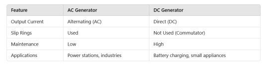
Conclusion:
An AC Generator is a crucial electrical device that converts mechanical energy into electrical energy using the principle of electromagnetic induction. It is widely used for power generation due to its efficiency, simplicity, and low maintenance. Understanding its working, construction, and applications is essential for Class 12 Physics students preparing for exams.
#11thclass#vavaclasses#science#biology#chemistry#physics#class 12#iit jee#neet#class 11 physics notes
0 notes
Text
Representation of AC Current and Voltage by Rotating Vectors - Phasors
Introduction:
In alternating current (AC) circuits, the magnitude and direction of current and voltage vary sinusoidally with time. To simplify their analysis, the concept of rotating vectors, known as phasors, is used. Phasors allow us to represent sinusoidal quantities as rotating vectors in a complex plane, making the analysis of AC circuits easier and more intuitive.

Understanding Phasors:
What is a Phasor?
A phasor is a rotating vector that represents a sinusoidal quantity. The length of the phasor corresponds to the peak value of the sine wave, and its angular position represents the phase of the wave at any given time.
Mathematical Representation:
The general expression for an AC voltage or current is: V(t) = V₀ sin(ωt + φ) Where: - V₀ = Peak voltage - ω = Angular frequency - φ = Phase angle - t = Time In phasor notation, this can be represented as: V = V₀ e^(j(ωt + φ)) where j is the imaginary unit.
Advantages of Using Phasors:
1. Simplifies the addition and subtraction of sinusoidal waveforms. 2. Converts differential equations into simple algebraic equations. 3. Provides a visual representation of phase differences between waveforms.
Phasor Diagram:
How to Draw a Phasor Diagram:
1. Draw a reference axis. 2. Represent the voltage or current as a vector with magnitude V₀. 3. The angle between the phasor and the reference axis corresponds to the phase angle φ. 4. As time progresses, the phasor rotates counter-clockwise at an angular velocity ω.
Applications of Phasors in AC Circuits:
1. Analyzing series and parallel AC circuits. 2. Determining impedance and phase relationships. 3. Analyzing resonance in LCR circuits. 4. Calculating power in AC circuits.
Conclusion:
Phasors are an essential tool for understanding and analyzing alternating current circuits. By representing sinusoidal quantities as rotating vectors in the complex plane, phasors simplify the mathematical analysis of AC circuits and help in visualizing phase relationships.
#vavaclasses#11thclass#science#biology#chemistry#physics#class 12#iit jee#neet#class 11 physics notes
0 notes
Text
Temperature Dependence of the Rate of a Reaction Notes
Introduction:
The rate of a chemical reaction depends on various factors, including temperature. Generally, an increase in temperature results in an increase in the reaction rate. This is because higher temperatures provide more energy to reactant molecules, leading to more frequent and effective collisions. The relationship between temperature and reaction rate is quantitatively described by the Arrhenius equation.

Effect of Temperature on Reaction Rate:
The speed of a reaction increases with temperature due to:
• Increased kinetic energy of reactant molecules. • Higher collision frequency. • Greater fraction of molecules possessing energy equal to or greater than the activation energy.
The Arrhenius Equation:
The Arrhenius equation mathematically expresses how reaction rate constants vary with temperature:
k = A e^(-Ea/RT)
Where:
• k = rate constant • A = pre-exponential factor • Ea = activation energy • R = universal gas constant (8.314 J/mol·K) • T = temperature (in Kelvin)
Activation Energy and Temperature Relationship:
Activation energy (Ea) is the minimum energy required for reactants to convert into products. • At lower temperatures, fewer molecules have sufficient energy to overcome the activation barrier. • At higher temperatures, a larger proportion of molecules exceed the activation energy, resulting in a faster reaction.
Temperature Coefficient and Rule of Thumb:
The temperature coefficient expresses how much the reaction rate changes with a 10°C rise in temperature. Generally, for most reactions:
Rate at (T+10)°C ≈ 2-3 × Rate at T°C
This means that for every 10°C increase in temperature, the reaction rate approximately doubles or triples.
Graphical Representation of Arrhenius Equation:
A logarithmic form of the Arrhenius equation is: ln k = ln A - (Ea/R) × (1/T) Plotting ln k vs. 1/T results in a straight-line graph with slope -Ea/R, which helps determine the activation energy experimentally.
Practical Applications of Temperature Dependence of Reaction Rate:
• Industrial Reactions: Optimizing temperature conditions in chemical manufacturing (e.g., Haber process for ammonia production). • Biological Systems: Enzyme-catalyzed reactions are highly temperature-sensitive. • Storage of Medicines and Food: Lowering temperature slows down degradation reactions. • Explosives and Combustion: Reactions are accelerated at higher temperatures, leading to controlled or uncontrolled explosions.
Conclusion:
Temperature significantly affects reaction rates by influencing molecular energy and collision frequency. The Arrhenius equation provides a mathematical framework to understand this dependency. By controlling temperature, chemical processes can be optimized for efficiency in industrial and biological applications.
#vavaclasses#11thclass#science#biology#chemistry#physics#class 12#iit jee#neet#class 11 physics notes
0 notes
Text
Bonding in Metal Carbonyls - Class 12 Chemistry Notes with Explanation
Introduction:
Metal carbonyls are coordination compounds in which a transition metal is bonded to one or more carbonyl (CO) ligands. These compounds play a crucial role in organometallic chemistry due to their unique bonding characteristics, stability, and industrial applications. The bonding in metal carbonyls is explained using the synergic bonding model, involving both σ-donation and π-back donation interactions.

Bonding in Metal Carbonyls – Class 12 Chemistry:
Metal carbonyls exhibit fascinating bonding properties due to the presence of carbonyl ligands, which interact with the metal center through a combination of donation and back-donation mechanisms.
Structure and Composition of Metal Carbonyls:
- Metal carbonyls are composed of a transition metal center bonded to CO ligands. - The general formula is M(CO)x, where ‘M’ represents the metal, and ‘x’ denotes the number of CO ligands. - Examples: Ni(CO)4, Fe(CO)5, Cr(CO)6. - These compounds can be mononuclear or polynuclear.
Synergic Bonding in Metal Carbonyls:
The bonding in metal carbonyls follows a synergic interaction involving: 1. σ-Bonding: The carbonyl ligand donates electron density to the metal via the lone pair on carbon (M ← CO). 2. π-Back Bonding: The metal donates electron density from its d-orbitals into the empty π* (antibonding) orbitals of CO (M → CO).
Molecular Orbital Approach to Metal Carbonyl Bonding
- The metal-carbon bond is a result of molecular orbital interactions. - The carbonyl ligand acts as both a donor and acceptor, stabilizing the complex. - The strength of back bonding depends on: - The oxidation state of the metal. - The number of CO ligands. - The nature of the metal (e.g., Fe, Ni, Cr).
Infrared Spectroscopy and Bonding in Metal Carbonyls
- The C≡O stretching frequency (νCO) in metal carbonyls helps determine the extent of π-back bonding. - Strong back bonding reduces the CO stretching frequency (lower νCO). - Examples: - Free CO: ~2143 cm⁻¹ - Fe(CO)5: ~2000 cm⁻¹ (due to back bonding)
Applications of Metal Carbonyls
1. Catalysis: - Used in industrial catalysts (e.g., hydroformylation and carbonylation). 2. Organic Synthesis: - Metal carbonyls are precursors for many organometallic compounds. 3. Industrial Processing: - Nickel carbonyl [Ni(CO)4] is used in metal refining. 4. Medical Applications: - Some metal carbonyls are explored for drug development.
Conclusion
Metal carbonyls are essential coordination compounds exhibiting unique synergic bonding through σ-donation and π-back bonding. Their structural properties influence their stability, spectroscopic behavior, and industrial applications. Understanding these interactions provides deeper insights into transition metal chemistry.
#vavaclasses#11thclass#science#biology#chemistry#physics#class 12#iit jee#neet#class 11 physics notes
0 notes
Text
Bonding in Coordination Compounds Class 12 Detailed Study Notes
Introduction:
Coordination compounds play a crucial role in chemistry, especially in biological and industrial applications. Understanding their bonding is essential for predicting their structures and properties. The bonding theories, including Valence Bond Theory (VBT), Crystal Field Theory (CFT), and Molecular Orbital Theory (MOT), help explain how metal ions interact with ligands to form stable complexes.

Bonding Theories in Coordination Compounds:
Valence Bond Theory (VBT):
VBT explains coordination bonding based on hybridization and overlapping of orbitals.
Key points include:
- Metal ions use empty orbitals to accommodate ligands. - Hybridization (sp3, dsp2, d2sp3) determines geometry. - Inner and outer orbital complexes depend on the d-electron configuration.
Example:
[Co(NH3)6]³⁺ undergoes d2sp3 hybridization, forming an inner orbital complex (low spin).
[Ni(CN)4]²⁻ exhibits dsp2 hybridization, resulting in a square planar geometry.
Limitations of VBT:
- Does not explain color in complexes. - Fails to address magnetic properties effectively. - Cannot distinguish between strong and weak field ligands quantitatively.
Crystal Field Theory (CFT):
CFT considers the electrostatic interactions between metal cations and ligands. It assumes ligands are point charges or dipoles affecting the metal’s d-orbitals.
Key Features:
- Splitting of d-orbitals into eg and t2g levels. - Explains color due to d-d transitions. - Accounts for paramagnetism and diamagnetism.
Example:
[Fe(CN)6]⁴⁻: Strong field ligand, low spin, t2g⁶ eg⁰ (octahedral).
[Fe(H2O)6]²⁺: Weak field ligand, high spin, t2g⁴ eg² (octahedral).
Crystal Field Splitting in Different Geometries:
- Octahedral: d-orbitals split into t2g (lower) and eg (higher) levels. - Tetrahedral: d-orbitals split into eg (lower) and t2g (higher) levels. - Square Planar: Further splitting with significant energy gap.
Molecular Orbital Theory (MOT) in Coordination Compounds:
MOT explains bonding using linear combination of atomic orbitals (LCAO). It accounts for sigma and pi bonding interactions.
Key Aspects:
- Bonding molecular orbitals (BMO) and antibonding molecular orbitals (ABMO). - Ligand’s contribution to the metal’s electronic structure. - Predicts bond strength, stability, and electronic transitions.
Example:
In [Co(NH3)6]³⁺, ligand-to-metal bonding involves sigma donation, leading to strong-field stabilization.
Applications of Bonding Theories in Coordination Compounds:
Industrial and Biological Importance:
- Hemoglobin (Fe complex): Oxygen transport in the blood. - Chlorophyll (Mg complex): Photosynthesis in plants. - Catalysts: Platinum complexes in hydrogenation reactions. - Medicinal Chemistry: Cisplatin as an anticancer drug.
Conclusion:
Bonding in coordination compounds is fundamental to understanding their behavior. While VBT provides a basic understanding, CFT and MOT offer deeper insights into electronic structure, magnetism, and color. These theories help explain various biological and industrial applications of coordination chemistry.
#vavaclasses#11thclass#science#biology#chemistry#physics#class 12#iit jee#neet#class 11 physics notes
0 notes
Text
AC Voltage Applied to an Inductor – Class 12 Physics Notes
Introduction:
When an alternating current (AC) voltage is applied to an inductor, the behavior of the circuit differs from that of a resistor. Inductors oppose changes in current due to self-induced emf, leading to a phase difference between voltage and current. This concept is essential in AC circuit analysis and finds applications in transformers, motors, and various electronic circuits.
AC Voltage Across an Inductor:
An inductor is a coil of wire that resists changes in current due to electromagnetic induction. When an AC voltage is applied across an inductor, the current flowing through it does not immediately follow the voltage but lags behind by 90°.
Mathematical Representation:
Using Kirchhoff’s Voltage Law (KVL), the equation for an AC circuit with an inductor is: V = L (dI/dt) For an AC source: V = V₀ sin(ωt) Solving for current: I = (V₀ / ωL) sin(ωt - 90°) This shows that current lags voltage by 90 degrees (π/2 radians).
Inductive Reactance (XL):
Inductive reactance (X_L) is the opposition offered by an inductor to AC, given by: X_L = ωL = 2πfL where: - f = frequency of AC (Hz) - L = inductance (H) The higher the frequency, the greater the opposition to current.
Phase Difference Between Voltage and Current:
- Voltage leads the current by 90° in a purely inductive circuit. - This phase shift is crucial in AC circuit analysis and power calculations.
Power in an Inductive Circuit:
The instantaneous power is given by: P = VI = V₀ sin(ωt) × I₀ sin(ωt - 90°) Since sin(ωt - 90°) = -cos(ωt), P = V₀ I₀ sin(ωt) (-cos(ωt)) Average power over a full cycle is zero, meaning no real power dissipation in a pure inductor. Energy is stored and released in the magnetic field.
Applications of Inductors in AC Circuits:
1. Transformers – Work on the principle of electromagnetic induction. 2. Motors and Generators – Use inductors to create magnetic fields. 3. Radio Tuning Circuits – Inductors filter and select desired frequencies. 4. Power Supplies – Inductive filters smooth out fluctuations.
Conclusion:
When AC voltage is applied to an inductor, the current lags behind the voltage by 90°, and the inductor opposes changes in current through inductive reactance. Inductors play a key role in AC circuits, from power distribution to communication systems. Understanding their behavior is essential for mastering electromagnetism and AC circuit analysis in Class 12 Physics.
#vavaclasses#11thclass#science#biology#chemistry#physics#class 12#iit jee#neet#class 11 physics notes
0 notes
Text
Class 12 Physics Transformers - Study Notes, Working, Uses
Introduction:
A transformer is a static electrical device that transfers electrical energy between two or more circuits through electromagnetic induction. It is widely used in power transmission and distribution systems to step up or step down voltage levels. Understanding transformers is essential for Class 12 students as it forms a crucial part of the Electromagnetic Induction chapter.

What is a Transformer?
A transformer is an electrical device that changes the voltage of alternating current (AC) without changing its frequency. It operates on the principle of electromagnetic induction.
Principle of a Transformer:
Transformers work on Faraday's Law of Electromagnetic Induction. When an alternating current passes through the primary coil, it creates a changing magnetic field, which induces a voltage in the secondary coil.
Mathematically, (Vs / Vp) = (Ns / Np)
Where: - Vs = Secondary voltage - Vp = Primary voltage - Ns = Number of turns in the secondary coil - Np = Number of turns in the primary coil
Types of Transformers:
Based on Functionality
- Step-Up Transformer: Increases voltage from primary to secondary. - Step-Down Transformer: Decreases voltage from primary to secondary.
Based on Construction:
- Core-Type Transformer: Windings surround the laminated core. - Shell-Type Transformer: Core surrounds the windings.
Based on Usage:
- Power Transformers: Used in transmission networks. - Distribution Transformers: Used in local electricity distribution. - Instrument Transformers: Includes Current and Potential transformers used for measurement.
Working of a Transformer:
1. AC Input: An alternating current (AC) flows through the primary coil. 2. Magnetic Field Generation: The AC produces a changing magnetic flux in the core. 3. Induced EMF: This varying flux induces a voltage in the secondary coil. 4. AC Output: The secondary coil delivers AC output, which can be stepped up or down depending on the coil turns.
Transformer Efficiency and Losses:
Efficiency Formula
Efficiency (η) = (P_out / P_in) × 100
Transformer Losses:
1. Copper Loss: Due to resistance in windings. 2. Iron Loss (Core Loss): Caused by eddy currents and hysteresis. 3. Flux Leakage Loss: Incomplete magnetic linkage. 4. Dielectric Loss: Occurs in insulation material.
Applications of Transformers:
- Power transmission and distribution. - Voltage regulation in electronic devices. - Used in welding machines. - Inverters and power supplies. - Used in measurement instruments.
Conclusion:
Transformers are fundamental devices in electrical engineering, playing a critical role in efficient power transmission and distribution. Understanding their working principle, types, and applications is essential for Class 12 Physics students. Mastering transformer concepts will aid in solving numerical problems and practical applications in the real world.
#vavaclasses#11thclass#science#biology#chemistry#class 12#physics#iit jee#neet#class 11 physics notes
0 notes
Text
Power in AC Circuit: The Power Factor – Class 12 Physics Notes
Introduction:
In AC circuits, power calculation is different from DC circuits due to the phase difference between voltage and current. The power factor plays a crucial role in determining the efficiency of the circuit. Understanding real power, apparent power, and reactive power is essential in analyzing AC circuits used in electrical systems.

Power in AC Circuits:
AC circuits involve alternating current and voltage, which may or may not be in phase. The power delivered depends on the phase angle (φ) between them. The three types of power in AC circuits are:
- Real Power (P): Actual power consumed (measured in watts, W)
- Apparent Power (S): Total power supplied (measured in volt-amperes, VA)
- Reactive Power (Q): Power due to reactance (measured in volt-amperes reactive, VAR)
The relation between these powers is given by:
S² = P² + Q²
What is Power Factor?
The power factor (PF) is the ratio of real power to apparent power. It indicates how effectively the electrical power is converted into useful work.
Power Factor (PF) = P / S = cos(φ)
- If PF = 1: Voltage and current are in phase, circuit is purely resistive.
- If PF < 1: Circuit has reactive components (inductive or capacitive).
- If PF = 0: Circuit is purely reactive (inductive or capacitive), no real power transfer.
Significance of Power Factor:
- A high power factor means efficient power usage.
- A low power factor causes energy losses and higher electricity bills.
- Industries and power grids aim to maintain a PF close to 1 to improve efficiency.
Power Factor in Resistive, Inductive, and Capacitive Circuits:
1. Purely Resistive Circuit:
- Voltage and current are in phase (φ = 0°).
- Power factor PF = cos(0) = 1.
2. Purely Inductive or Capacitive Circuit:
- Voltage and current are out of phase by 90°.
- Power factor PF = cos(90) = 0 → No real power consumption.
3. RL or RC Circuit (Mixed Load):
- Phase angle lies between 0° and 90°.
- Power factor is between 0 and 1, depending on the reactance.
How to Improve Power Factor?
1. Use Capacitor Banks – They counteract inductive reactance.
2. Synchronous Condensers – Help regulate reactive power.
3. Phase Advancers – Improve PF in AC motors.
Solved Example on Power Factor:
Q: A circuit has an apparent power of 500 VA and a real power of 400 W. Find the power factor.
Solution:
PF = P / S = 400 / 500 = 0.8
Thus, the power factor is 0.8 (lagging).
Conclusion:
Power in AC circuits depends on the power factor, which determines the efficiency of energy usage. A high power factor reduces energy losses, while a low power factor increases power wastage. Understanding power factor correction methods is essential for improving circuit efficiency.
#vavaclasses#11thclass#science#biology#chemistry#physics#class 12#iit jee#neet#class 11 physics notes
0 notes
Text
Class 12 Physics Study Notes On AC Voltage Applied to a Series LCR Circuit
Introduction:
A series LCR circuit consists of an inductor (L), a capacitor (C), and a resistor (R) connected in series to an alternating current (AC) source. The analysis of such a circuit is crucial for understanding the behavior of AC circuits in practical applications, including resonance, impedance, and phase relationships. This study note provides a comprehensive explanation of the response of a series LCR circuit to an AC voltage.
Understanding the Series LCR Circuit:
A series LCR circuit is driven by an alternating voltage source given by: V = V₀ sin(ωt) where V₀ is the peak voltage, and ω is the angular frequency of the AC source. Each component (R, L, and C) has a different behavior in the presence of AC, affecting the circuit's total impedance and phase angle.
Impedance of the Series LCR Circuit:
The total impedance (Z) of the circuit is given by: Z = √(R² + (X_L - X_C)²) where: - X_L = ωL (Inductive reactance) - X_C = 1/(ωC) (Capacitive reactance) The impedance determines the overall resistance to the AC current and affects the circuit's current flow.
Phasor Diagram and Phase Angle:
The phase angle (ϕ) between the applied voltage and the current is given by: tan ϕ = (X_L - X_C) / R A phasor diagram represents the relationship between the voltage and current in the circuit and helps in analyzing phase shifts.
Resonance in Series LCR Circuit:
Resonance occurs when the inductive reactance equals the capacitive reactance: X_L = X_C → ω₀L = 1/(ω₀C) Solving for ω₀, we get the resonance frequency: ω₀ = 1/√(LC) At resonance: - Impedance is minimum and equals R. - Current is maximum. - Voltage across L and C are equal and opposite, canceling out.
Power and Power Factor in LCR Circuit:
The average power (P) in the circuit is given by: P = V_rms I_rms cosϕ where cosϕ is the power factor, determining the efficiency of power transfer. At resonance, the power factor is 1, meaning all power is consumed by the resistor.
Applications of Series LCR Circuit:
Radio Tuning: LCR circuits are used in radio receivers for frequency selection. Filters in Communication Systems: These circuits help in signal filtering. Power Distribution: Used in AC power systems to manage voltage levels and phase angles. Resonant Transformers: Used in induction heating and wireless power transfer.
Conclusion:
A series LCR circuit plays a fundamental role in AC circuit analysis, demonstrating crucial concepts like resonance, impedance, and phase relationships. Understanding this circuit is essential for students in Class 12 Physics, as it has numerous practical applications in electrical and communication systems.
#vavaclasses#11thclass#science#biology#chemistry#physics#class 12#iit jee#neet#class 11 physics notes
0 notes