
Don't wanna be here? Send us removal request.
Statistics
We looked inside some of the posts by amystepper and here's what we found interesting.
Average Info
Notes Per Post
1
Likes Per Post
1
Reblog Per Post
0
Reply Per Post
0
Time Between Posts
23 days
Number of Posts By Type
Text
10
Last Seen Tumblr Blogs


Fun Fact
Tumblr was acquired by Yahoo for $1.1B in 2013.
Text
What are the precautions for using integrated stepper motors?
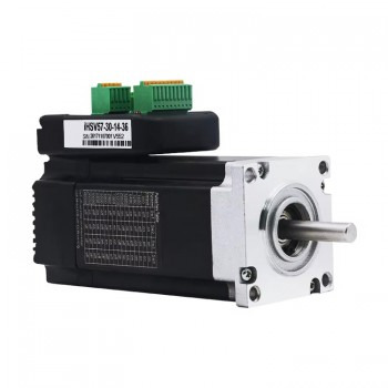
1.Basic definition of integrated stepper motors Integrated stepper motors are innovative motor products that integrate the driver with the motor body. By embedding the drive circuit directly into the motor, it achieves a high degree of integration between the motor and the driver, simplifies the installation process, reduces maintenance costs, and has significant advantages in space-constrained applications due to its compact structural design.

2.Working principle of integrated stepper motors The working principle of integrated stepper motors is based on the effects of electromagnetic induction and magnetic torque. When the motor receives a pulse signal, the driver controls the rotation angle and speed of the motor according to the frequency and duty cycle of the signal. Specifically, the driver energizes each phase winding of the motor in turn to generate a rotating magnetic field, which in turn generates a magnetic torque in the rotor, causing the rotor to rotate according to a predetermined step angle. By precisely controlling the frequency and number of pulse signals, precise positioning and speed regulation of the motor can be achieved.
3.Main advantages of integrated stepper motors
1.Integrated design: The integrated stepper motor integrates the driver and the motor body, simplifies the system structure, and reduces the difficulty of installation and maintenance. This design reduces external connection points, thereby reducing the failure rate and improving the reliability of the system. 2. High-performance control: The closed-loop control technology is adopted to realize precise control of the motor by real-time feedback of the motor's position and speed information, thereby improving the stability and accuracy of the system. The closed-loop control technology effectively suppresses the step-out phenomenon of the stepper motor and improves the positioning accuracy and repeat positioning accuracy of the system. 3. High-efficiency energy conversion: The design of the motor and the driver is optimized, the power conversion efficiency is improved, the energy consumption is reduced, and it meets the requirements of green environmental protection. This design helps to reduce energy consumption and maintenance costs and improve the overall economic benefits of the equipment. 4. Intelligent operation: It supports a variety of control protocols and interface standards, and can achieve seamless connection with devices such as host computers or PLCs, which is convenient for users to conduct remote monitoring and debugging. This intelligent operation improves the response speed of the system, reduces the complexity of wiring, and makes system integration more convenient and efficient. 5. Enhanced anti-interference ability: By optimizing the electromagnetic compatibility design and adopting advanced signal processing technology, the system's anti-interference ability to electromagnetic interference and environmental noise is enhanced.
6.Reduce operating costs: High-efficiency energy conversion and intelligent operation help reduce energy consumption and maintenance costs and improve the overall economic benefits of the equipment.

4.Precautions for the use of integrated stepper motors
1.Inspection before installation: Before installation, check whether there is mechanical collision or cross interference of other objects around the integrated stepper motor. Choose a solid, flat ground to ensure that the motor is placed stably without shaking or tilting. When connecting the power supply and other auxiliary electrical equipment, pay attention to the correctness of the power supply voltage, frequency and phase sequence.
2.Daily inspection and maintenance: Before daily use, check whether the waveform of the power supply voltage and current of the integrated stepper motor is normal, and whether the various parameters meet the requirements. At the same time, check the mechanical parts of the motor (such as bearings, transmission belts, reducers, etc.) to ensure that all parameters are in normal condition.
3.Operation precautions: Before starting, keep the operating switch in the off state, and set the controller and power switch correctly. When starting, the speed and position should be adjusted gradually to ensure that the motor runs smoothly. During acceleration, try to avoid sudden acceleration or sudden braking of the motor to avoid affecting the life and stability of the motor. During normal operation, if an abnormal condition (such as mechanical shock, power failure, etc.) is encountered, the operation must be stopped immediately and the fault can be eliminated before continuing to use. 4. Maintenance procedures: Keep the equipment clean and tidy, clean the integrated stepper motor regularly, and avoid damage to the machine by dust, grease and particles. It is recommended to perform a comprehensive cleaning and maintenance of the equipment once a month. 5. Working environment requirements: The insulation material standard of the stepper motor is ULB grade, the surface temperature of the motor should be lower than 100°, and the coil temperature rise should be controlled within 80K. High temperature will affect the safety of the insulation system and the stability of the motor. Therefore, special attention should be paid to controlling the temperature rise of the motor when using it in a high temperature environment. This can be achieved by strengthening the heat dissipation conditions or reducing the working current of the motor.
0 notes
Text
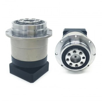
What are the design principles of helical planetary gearboxes?
1.Working principle of helical planetary gearboxes The working principle of helical planetary gearboxes is based on the unique movement of planetary gears. The planetary gears not only rotate around their own axes, but also rotate with the planet carrier around the axes of other gears. This structure allows power to be input and output in multiple directions. Through devices such as clutches or brakes, the rotation of a certain axis can be flexibly limited when necessary to achieve transmission of only two axes.
2.Driving mode of helical planetary gearboxes
1.Single planetary gear drive: This is the most basic driving mode, including a sun gear, several planetary gears and a gear ring. The sun gear receives power through the input shaft, drives the planetary gear to rotate around its own axis, and drives the gear ring to output power through the planet carrier. This driving mode has a simple structure and is suitable for a variety of transmission needs.
2.Double planetary gear drive: In the double planetary gear drive, two planetary gears work simultaneously, and each planetary gear has an independent sun gear, planetary gear and gear ring. This driving mode can provide greater torque and higher transmission efficiency, and is often used in occasions requiring high power output. 3. Multi-planetary gear drive: By connecting multiple planetary gears in series or in parallel, more complex transmission ratios and higher transmission efficiency can be achieved. This drive method is suitable for occasions where the transmission ratio and torque output need to be precisely controlled.
3.Application skills of helical planetary gearboxes 1. Operation skills when installing transmission parts: When installing transmission parts, attention must be paid to the softness of the operation. It is forbidden to use rough tools such as hammers. It is best to use the internal threads of the mounting fixture and the end shaft for installation. Press the transmission parts into the reducer with the force of screwing in the bolts, so as to protect the internal parts of the reducer from damage. 2. Alignment skills of the transmission center axis: When installing the planetary gearbox, pay special attention to the alignment of the transmission center axis. The alignment error cannot exceed the use compensation amount of the coupling used by the reducer. After the reducer is aligned as required, a more ideal transmission effect and a longer service life can be obtained.
3.Fixing skills: Ensure that the planetary gearbox is fixed steadily and firmly. It is usually installed on a horizontal foundation or base, and ensure that the oil in the drain groove can be discharged and the cooling air circulates. If the fixation is not good or the foundation is unreliable, it may cause vibration and damage to the bearings and gears.
4.Selection of installation orientation: The installation orientation should ensure the convenience of operation of the staff, including easy access to the cursor, vent plug and drain plug. After the installation is completed, the inspector should check the accuracy of the installation orientation in sequence to ensure the reliability of each fastener.

4.Design principles of helical planetary gearbox
1.Material selection and heat treatment: The selection of gear material has an important influence on the strength, wear resistance and service life of the gear. Commonly used materials include carbon steel, alloy steel and stainless steel. Heat treatment processes such as quenching and tempering can further improve the hardness and wear resistance of the material.
2.Selection of module and pressure angle: The module is an important parameter in gear design, which directly affects the size and strength of the gear. The choice of pressure angle affects the transmission efficiency and noise of the gear. Helical gears usually use a smaller pressure angle to reduce transmission noise and vibration. 3. Lubrication and sealing design: Good lubrication is the key to ensuring gear transmission efficiency and service life. The lubrication method can be oil bath lubrication or oil mist lubrication, and the specific choice depends on the structure and working environment of the gearbox. The sealing design should prevent foreign debris from entering the gearbox and affecting lubrication and transmission efficiency. 4. Clearance control: The clearance between the gear and the shaft, and the gear and the housing needs to be precisely controlled to ensure the smoothness and stability of the gear transmission. Too large a clearance will lead to a decrease in transmission efficiency, while too small a clearance may cause overheating and wear.
5.Balance design and dynamic analysis: When designing, it is necessary to consider the dynamic characteristics of gear transmission, such as unbalance and vibration, and optimize the design through dynamic analysis to reduce vibration and noise during transmission. In addition, the balance design can ensure the stability and life of the gear at high speed. 6. Strength calculation and verification: During the design process, strength calculation and verification are required to ensure that the gear can withstand the corresponding load without damage under various working conditions. Commonly used calculation methods include finite element analysis and empirical formula calculation.
0 notes
Text
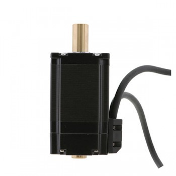
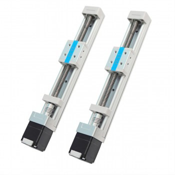
Driving mode and core features of hollow shaft stepper motors
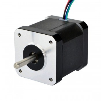
1.Definition and structure of hollow shaft stepper motors Hollow shaft stepper motors are mainly composed of stators and rotors. The stator is fixed and usually consists of multiple coils; the rotor is a hollow structure with multiple magnetic poles inside. This design makes the motor more stable during operation, and the hollow shaft design also provides additional heat dissipation space for the motor.

2.Driving mode of hollow shaft stepper motors
1.Single voltage drive: In this mode, the motor winding is powered by only one direction voltage during operation. When the input signal is high, a sufficiently large base current is provided to make the transistor in a saturated state, and the power supply voltage acts entirely on the motor winding; when the input signal is low, the transistor is cut off and no current passes through the winding. 2. High and low voltage drive: In order to make the winding quickly reach the set current when powered on, and the winding current quickly decays to zero when turned off, while improving efficiency, high and low voltage drive modes have emerged. At the front edge of the conduction, a high voltage is used to supply power to increase the current rise rate, while a low voltage is used to maintain the winding current after the front edge. 3. Constant current chopper drive: This method is implemented through the self-excited constant current chopper drive block diagram, which converts the current value of the stepper motor winding into a certain proportion of voltage, and compares it with the preset value output by the D/A converter to control the motor current.
3.Core features of hollow shaft stepper motors 1. Structural design: The main structure of the hollow shaft stepper motor includes a stator and a rotor, in which the rotor is usually stacked with multiple silicon steel sheets, and the stator is fixed. This design makes the motor more stable during operation, and the hollow shaft design also provides additional heat dissipation space for the motor. 2. Wiring and heat dissipation: The design of the hollow shaft not only allows other parts of the motor to pass through, but also integrates additional functions as needed, such as heat dissipation, connection to other devices, etc. This design greatly optimizes the mechanical design, facilitates wiring, avoids cable distortion and damage, and saves design space and production costs. 3. High-precision requirements: For hollow shaft stepper motors with precision requirements, the inner hole diameter and thread precision requirements are very high, mainly used to meet the needs of using third-party trapezoidal screws or ball screws. This high-precision design ensures the mechanical precision and operating precision of the entire stepper screw motor.
4.Common applications of hollow shaft stepper motors 1. Automated production lines and robots: Hollow shaft stepper motors are used in automated production lines to accurately control the motion trajectory of the robot arm and improve the efficiency and precision of the production line. In the field of robotics, they improve the operating accuracy and flexibility of robots and are widely used in robotic arms and bionic prostheses, etc.
2. Medical devices: In the medical field, hollow shaft stepper motors are used in surgical robots and other medical equipment to ensure high-precision surgical operations and equipment control. 3. CNC machine tools: In the field of CNC machine tool manufacturing, stepper motors are used to accurately control the processing position and speed of workpieces to achieve high-precision processing. 4. Aerospace: Hollow shaft stepper motors have important applications in the aerospace field, such as rapid adjustment of missile flight direction, follow-up control of high-power optical drives, etc. Due to their light weight, small size and low energy consumption, hollow shaft motors are also widely used in aircraft and other aviation equipment. 5. Household appliances: Stepper motors are widely used in household appliances, such as refrigerator door locks, robot vacuum navigation, TV channel adjustment, etc. 6. Automobile manufacturing: In the field of automobile manufacturing, stepper motors are used for engine motor control, temperature control and air conditioning temperature adjustment, etc. 7. Optical and laser equipment: Hollow shaft stepper motors perform well in applications that require high-precision control, such as laser cutting, laser welding and laser marking. Its hollow structure facilitates the transmission of light beams and simplifies optical path design and integration. 8. Other applications: In addition, hollow shaft stepper motors are also used in various portable instruments, personal equipment, field operation instruments and equipment, electric vehicles, etc., to meet the needs of stable and long-lasting drag drive components.
Source:https://community.networkofcare.org/blogs/amber_stepper_motor/archive/2025/05/06/driving-mode-and-core-features-of-hollow-shaft-stepper-motors.aspx
0 notes
Text
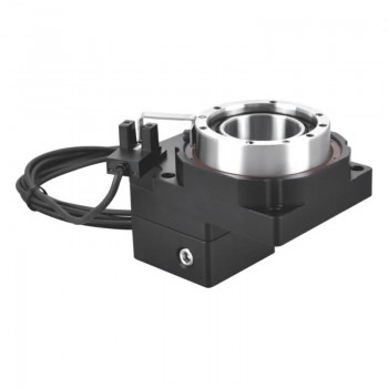
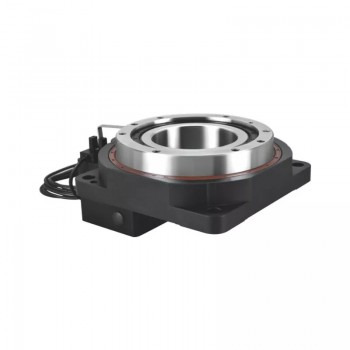
What are the installation precautions of hollow rotary actuators?
1.Introduction to the structure of hollow rotary actuators The main structure of hollow rotary actuators includes conveyor belts, motors, hydraulics and electronic controls. Its moving part is a ring conveyor belt, which can realize the combination of translation and rotation, thereby improving production efficiency. The motor and hydraulic drive parts of the equipment adopt advanced modular design, making the equipment structure more compact and reasonable, with higher reliability and stability.
2.Driving mode of hollow rotary actuators
1.Gear transmission: Power and rotational motion are transmitted through the meshing of gears. Gear transmission can achieve high-precision transmission ratios, which is suitable for heavy equipment and production lines. It has the characteristics of strong load-bearing capacity, mature technology and high reliability.
2.Direct drive technology: The motor is directly connected to the hollow rotary platform to achieve efficient and precise rotational motion. Direct drive technology reduces the intermediate transmission links and improves energy utilization. At the same time, it has high precision and stability and is easy to maintain. 3. Belt drive: The belt is used to drive the hollow rotary platform, which is suitable for small and medium-sized rotary platforms and has the advantages of simple structure and convenient maintenance. 4. Electric drive: The electric motor is used to directly drive the hollow rotary platform, which has the advantages of high transmission efficiency and low noise, and is suitable for small and medium-sized rotary platforms.
3.Technical advantages of hollow rotary actuators 1. High precision and high efficiency: The hollow rotary actuator adopts a precise control system and a high-precision servo motor to achieve high positioning repeatability and accuracy. For example, in the field of semiconductor wafer inspection, the hollow rotary platform can achieve a positioning accuracy of ±5 arc seconds, ensuring that the million-pixel inspection equipment can operate stably at nanometer resolution. 2. High load-bearing capacity and stability: The design of the hollow rotary actuator makes it have high load-bearing capacity. For example, some models of hollow rotary platforms can easily carry 150kg of precision inspection instruments to complete 360° scanning without dead angles. In addition, its rigidity performance is also excellent. The turntable is supported by a set of precision cross roller bearings, which can withstand various torques such as radial, axial, and overturning. The rigidity is more than 10 times that of traditional bearings. 3. Compact structure and flexibility: The hollow rotary actuator adopts a hollow structure design, which makes the equipment compact and occupies a small area, suitable for space-constrained application scenarios. At the same time, its modular design allows for quick replacement of the end effector, which is convenient for integrating force control sensors and visual systems to achieve rapid process switching. 4. Wide application scenarios: Hollow rotary actuators are widely used in many fields. For example, in CNC indexing devices, precise indexing control is provided to improve processing accuracy; at the joints of the manipulator, the hollow structure facilitates pipeline layout, making the manipulator move more smoothly and perform complex tasks; in the fourth processing axis of the machine tool, more dimensional processing operations are realized; in the field of military radar, it helps the radar to accurately adjust the angle and improve the detection performance; in the automated production line, it controls the rotation positioning of material transmission and processing links, etc.
4.Precautions for installation of hollow rotary actuators 1. Preparation: Before installation, it is necessary to confirm whether the motor and hollow rotary platform are intact, and check whether the dimensions of each component match, including the positioning boss of the motor, the input shaft and the reducer groove, and the size and matching tolerance. At the same time, clean the installation surface to ensure that there is no anti-rust oil or other impurities. 2. Installation location and environment: The hollow rotary platform should be installed indoors to avoid direct sunlight and heat radiation. The working environment temperature should be between 0-50 degrees, and the temperature below the origin sensor should not exceed 42 degrees. In addition, the working environment should be dry to avoid flammable and explosive gases and dust, oil, splashing water, etc. 3. Connection method: The motor and the rotary platform equipment should be naturally connected to ensure that the concentricity of the reducer output shaft and the motor input shaft is consistent, and the outer flange is parallel. It is forbidden to use tools such as hammers when connecting to prevent excessive axial force or radial force from damaging the bearing or gear. 4. Sealing: Pay special attention to the sealing of the equipment, especially the sealing of the shaft of the servo hollow rotary platform. During installation, the mounting bolts at the diagonal position should be tightened gradually to ensure the internal sealing of the equipment and prevent environmental pollution. 5. Electrical connection: The hollow rotating platform requires power support, so the electrical lines need to be connected during installation. The length and color of the wires should be easy to manage and maintain, and the signal wires should be connected to the controller to ensure the operation control of the equipment. 6. Debugging and inspection: After the installation is completed, perform detailed positioning and precision adjustments to ensure smooth and stable operation of the equipment. Debug and inspect the electrical system to ensure its safety and stability.
Source:https://community.networkofcare.org/blogs/amber_stepper_motor/archive/2025/04/11/what-are-the-installation-precautions-of-hollow-rotary-actuators.aspx
0 notes
Text
Main functions and maintenance methods of Linear Guide Rail
1.What is Linear Guide Rail? Linear Guide Rail is an important component used in mechanical design to support and guide moving parts to make reciprocating linear motion in a given direction. It consists of guide rails, sliders, rolling elements and retainers. Through the infinite rolling cycle of balls between the sliders and guide rails, high-speed and high-precision linear motion under high loads is achieved.
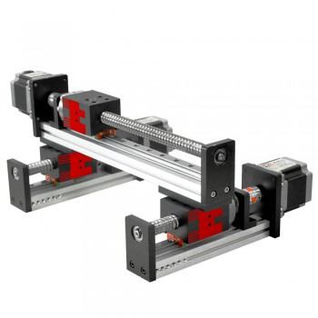
2.Operating principle of Linear Guide Rail The operating principle of Linear Guide Rail is mainly based on rolling guidance, and low-friction linear motion is achieved through the rolling of steel balls between the sliders and guide rails. Specifically, Linear Guide Rail consists of slide rails, sliders, balls, ball retainers and ball return grooves. There are many balls installed between the sliders and the guide rails. These balls perform infinite rolling cycles when the sliders move, thereby converting sliding friction into rolling friction, significantly reducing the friction coefficient and improving motion efficiency and precision.
3.Main functions of Linear Guide Rail 1.Load bearing and guiding: Linear Guide Rail plays a role of load bearing and guiding in mechanical design, supporting and guiding moving parts to make reciprocating linear motion in a given direction. It can achieve high-precision linear motion under high load. 2.Improve positioning accuracy: Since Linear Guide Rail adopts rolling friction, the friction coefficient is low, and the difference between dynamic friction and static friction is small, the bed will not slip during operation, and the positioning accuracy of micron level can be achieved. 3.Reduce wear: Traditional sliding guides will cause wear and affect accuracy due to oil film backflow and insufficient lubrication. The rolling guide of Linear Guide Rail has very little wear, and the machine can maintain accuracy for a long time. 4.Suitable for high-speed movement: Linear Guide Rail has low friction, and only a small amount of power is needed to make the bed run, which is especially suitable for occasions with frequent reciprocating operation. At the same time, it is suitable for high-speed operation because the heat generated by its friction is small. 5.Bear multi-directional loads: The special structural design of Linear Guide Rail enables it to bear loads in the upper, lower, left and right directions at the same time. Compared with traditional sliding guides, it has a stronger lateral load bearing capacity in the direction of parallel contact surfaces. 6.Easy assembly and interchangeability: The assembly of Linear Guide Rail is simple. You only need to mill or grind the assembly surface of the guide rail on the bed, and fix the guide rail and slider to the machine with a specific torque according to the recommended steps. In addition, Linear Guide Rail is interchangeable, and the slider or guide rail can be replaced separately, so that the machine can regain high-precision guidance.
4.Maintenance method of Linear Guide Rail 1.Daily cleaning: Regularly use a clean cotton cloth or a soft brush to remove impurities such as dust, chips and oil on the surface of the linear guide. Avoid using rough materials when cleaning to avoid scratching the surface of the guide rail. You can use a mild detergent with a cleaning cloth to wipe it, but be careful that the detergent cannot contain corrosive ingredients such as strong acids and alkalis. After cleaning, it should be wiped dry in time to prevent moisture residue from causing rust on the guide rail. 2.Lubrication and maintenance: Good lubrication is essential for the normal operation and service life of Linear Guide Rail. Select appropriate lubricants, such as lubricating oil or grease, according to the use environment and working conditions, and ensure that the lubricant is evenly applied to the sliding surface of the guide rail. Check the state of the lubricant regularly, replenish and replace the lubricant in time to prevent the lubricant from deteriorating or contaminating. 3.Prevent overload and impact: Overload and sudden impact loading should be avoided when using Linear Guide Rail. Overload will cause the wear of the guide rail to increase, reduce its accuracy and service life. When designing and using the system of linear guide rails, the load should be reasonably arranged according to the load-bearing capacity and working requirements of the guide rails, and necessary buffering and shock-absorbing measures should be taken. 4.Regular inspection and adjustment: Regularly inspect the Linear Guide Rail, including the flatness, straightness and clearance of the guide rail. Professional measuring tools can be used for detection, such as level, laser interferometer, etc. If deviation or wear of the guide rail is found, it should be adjusted or the relevant parts replaced in time. At the same time, check whether the fixing bolts and connectors of the guide rail are loose. If they are loose, tighten them in time. 5.Storage precautions: If the Linear Guide Rail needs to be stored for a long time, appropriate protective measures should be taken. Wipe the surface of the guide rail clean, apply a layer of anti-rust oil or lubricant, and wrap it with plastic film or oil paper. The storage environment should be kept dry and ventilated, avoiding direct sunlight and high temperature environment. The status of the guide rail should be checked regularly during storage, and any abnormalities should be handled in time.
Source:https://community.networkofcare.org/blogs/amber_stepper_motor/archive/2025/03/20/main-functions-and-maintenance-methods-of-linear-guide-rail.aspx
0 notes
Text
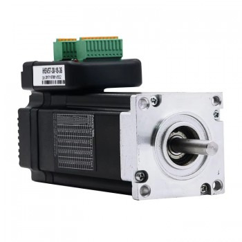
Performance optimization method of integrated servo motor
1.Definition and characteristics of integrated servo motor The integrated servo motor has an integrated servo driver inside, which can directly receive signals from the controller and perform corresponding actions. Compared with traditional split servo motors, integrated servo motors reduce the number of external connection components, reduce the complexity and cost of the system. In addition, due to the integrated design, integrated servo motors also have advantages in performance, such as higher precision and faster response speed.
2.Basic working principle of integrated servo motor When the integrated servo motor receives a pulse, it will rotate the angle corresponding to the pulse to achieve displacement. Since the integrated servo motor itself has the function of sending pulses, each rotation angle will send a corresponding number of pulses, so that the system can know how many pulses are sent to the servo motor and how many pulses are received back, so as to accurately control the rotation of the motor and achieve precise positioning with an accuracy of 0.001mm.
3.Structure of integrated servo motor 1.Stator: The stator is mainly made of laminated silicon steel sheets and is used to fix the magnetic field of the motor. The stator is the stationary part of the motor. After the winding is energized, a rotating magnetic field is generated to provide a power source for the operation of the motor. 2.Rotor: The rotor is usually composed of permanent magnets or electromagnets and is the rotating part of the motor. In permanent magnet servo motors, the rotor has built-in permanent magnets and can generate a magnetic field without external power supply. The rotor begins to rotate under the action of the rotating magnetic field generated by the stator, converting electrical energy into mechanical energy to drive the load to operate. 3.Encoder: The encoder is used to monitor the position and speed of the motor in real time and feed this information back to the control system to form a closed-loop control. Common encoders are photoelectric encoders and magnetic encoders. The encoder is a key component for achieving high-precision control of integrated servo motors. 4.Bearings and end covers: The bearings are used to support the rotation of the rotor to reduce friction and wear; the end covers are used to seal the inside of the motor to prevent dust and moisture from entering. These components together ensure the stable operation and long life of the motor. 5.Controller: The controller is the core component of the integrated servo motor and is mainly responsible for controlling the speed, position and other parameters of the motor. The controller usually uses a digital signal processor (DSP) or a microcontroller (MCU) chip, which has the characteristics of high-speed computing and high-precision control. 6.Driver: The driver is the power source of the integrated servo motor and is mainly responsible for converting the motor's control signal into a motor drive signal. Drivers usually use power semiconductor devices such as MOSFET, IGBT, etc., which have the characteristics of high efficiency and high reliability. 7.Sensor: The sensor is mainly used to detect the position, speed, acceleration and other parameters of the motor, and feed this information back to the controller and driver. Common sensors include encoders, Hall elements, potentiometers, etc.

4.Performance optimization method of integrated servo motor 1.Motor selection and parameter adjustment: Select a suitable servo motor according to actual needs to avoid waste or insufficiency caused by excessive or insufficient power. Adjust the motor's inductance, resistance, rotor inertia and other parameters to improve the motor's response speed and accuracy. 2.Optimize the transmission system: Reduce friction and inertia loss in the transmission chain, use low-friction transmission devices and efficient transmission ratios, and significantly improve transmission efficiency. Redesign the mechanical structure, reduce the inertia of components, or optimize the mechanical motion trajectory to reduce the load and thus increase the motor speed. 3.Application of advanced control algorithms: The use of advanced control algorithms, such as vector control, direct torque control, fuzzy control, neural network control, etc., can greatly improve the control accuracy and response speed of the servo motor. 4.Regular inspection and maintenance: Regularly inspect and maintain the integrated servo motor, including cleaning, lubrication, tightening, etc., to ensure that the motor is in good operating condition. Once a motor fault or abnormality is found, it should be handled in time to avoid the expansion of the fault and cause greater damage to the motor. 5.Power supply stability: The integrated servo motor has high requirements on the quality of the power supply, and the power supply voltage fluctuation will directly affect the speed control accuracy and response speed of the motor. Therefore, it is necessary to ensure that the power supply voltage is stable within the rated range, and the power supply waveform can be trimmed by adding filtering circuits. 6.Heat dissipation optimization: In the process of improving the performance of the integrated servo motor, pay attention to the heat dissipation of the motor. By improving the heat dissipation design, such as adding heat sinks, using fans or liquid cooling systems, etc., ensure that the motor will not affect performance due to overheating when running at high speed. 7.Feedback system debugging: It is very important to ensure the accuracy and stability of the encoder or sensor. Perform calibration and inspections regularly to ensure the accuracy of the feedback system and handle any abnormalities promptly. 8.Advanced debugging tips: Use vibration analysis tools to identify mechanical vibration problems and reduce vibration and resonance by adjusting and balancing the components of the transmission system.
Source:https://community.networkofcare.org/blogs/amber_stepper_motor/archive/2025/02/25/performance-optimization-method-of-integrated-servo-motor.aspx
0 notes
Text
Performance debugging method of servo motor
1.What is a servo motor? A servo motor is an engine that controls the operation of mechanical components in a servo system, and has the characteristics of high precision, high speed and high efficiency. It can convert voltage signals into torque and speed to drive the control object. The servo motor drives the load to move by receiving control signals, and detects the position, speed, acceleration and other parameters of the load in real time through sensors, and feeds back to the controller for adjustment, thereby achieving high-precision control.
2.Working principle of servo motor The working principle of servo motor is based on a closed-loop feedback control system, which can achieve precise position, speed and torque control. Servo motors are mainly composed of controllers, drivers and encoders. The controller receives external position or speed instructions and converts them into electrical signals to supply to the motor. The driver supplies three-phase electricity to the motor through a power supply to form an electromagnetic field, so that the rotor rotates under the action of the magnetic field. The encoder detects the position and speed information of the rotor in real time and feeds it back to the driver. The driver compares the feedback value with the target value and adjusts the rotation angle of the rotor to achieve precise control.
3.Servo motor drive mode 1.Position control drive mode: This drive mode controls the object by controlling the position of the motor. Usually, a position sensor is required to detect the position of the motor. Its advantages are high control accuracy, but high cost, and insufficient in instantaneous torque and response speed. 2.Speed control drive mode: The object movement is controlled by controlling the motor speed. The response speed is fast and no position sensor is required. However, it is not as good as the position control drive mode in terms of control accuracy and instantaneous torque. 3.Torque control drive mode: The object movement is controlled by controlling the motor torque. The response speed is fast, and the instantaneous torque and control accuracy are good. However, the torque sensor is required for feedback control, so the cost is high. 4.DC speed control drive: The speed is changed by controlling the voltage and current of the motor. The operation is simple but the control accuracy is low. It is suitable for occasions that do not require high-precision control and positioning. 5.Step speed drive: It controls the number of steps and speed of the motor by providing a pulse signal. It has high positioning accuracy and control accuracy, but the torque is small and cannot withstand excessive loads. 6.Closed-loop control drive: By installing an encoder or other sensor on the motor, the position and speed of the motor rotation are fed back to the controller to achieve precise closed-loop control.
4.Performance debugging method of servo motor 1.Motor parameter setting: Before debugging the servo motor, it is necessary to set the basic parameters of the motor, such as rated voltage, rated current, rated speed, etc. These parameters can usually be found on the nameplate of the motor. The purpose of setting these parameters is to ensure that the motor operates within the normal working range and avoid damage to the motor due to improper parameter setting. 2.Encoder parameter setting: The encoder is an important part of the servo motor and is used to measure the speed and position of the motor. During the debugging process, the encoder type (such as absolute, incremental) and resolution (such as the number of pulses per revolution) need to be set to ensure the compatibility of the encoder and the motor. 3.Speed loop debugging: The speed loop is an important link in the servo system and is used to control the speed of the motor. The proportional (P), integral (I), and differential (D) parameters of the speed loop need to be set to achieve precise control of the motor speed. Usually start with a small value and gradually increase these parameters until the system is stable. 4.Position loop debugging: The position loop is another important link in the servo system, which is used to control the position of the motor. The proportional (P), integral (I), and differential (D) parameters of the position loop need to be set to achieve precise control of the motor position. Again, these parameters should start with a small value and gradually increase until the system is stable. 5.Matching the motor and the drive: It is very important to ensure the match between the motor and the drive. The power, torque, speed and other parameters of the motor need to be checked to ensure that the output capacity of the drive meets the needs of the motor. If necessary, adjust the output parameters of the drive to adapt to the motor. 6.Optimize the transmission system: Reducing friction and inertia losses in the transmission chain, using low-friction transmission devices and efficient transmission ratios can significantly improve transmission efficiency. Redesign the mechanical structure, reduce the inertia of the components, or optimize the mechanical motion trajectory to reduce the load and thus increase the motor speed. 7.Application of advanced control algorithms: The use of advanced control algorithms, such as vector control, direct torque control, fuzzy control, neural network control, etc., can greatly improve the control accuracy and response speed of the servo motor. In particular, model predictive control and adaptive control can automatically adjust the control parameters based on the system model or real-time data to adapt to the dynamic changes of the system. 8.Regular inspection and maintenance: Regularly inspect and maintain the servo motor, including cleaning, lubrication, tightening, etc., to ensure that the motor is in good operating condition. Once a motor fault or abnormality is found, it should be handled in time to avoid the expansion of the fault and cause greater damage to the motor.
Source:https://community.networkofcare.org/blogs/amber_stepper_motor/archive/2025/01/16/performance-debugging-method-of-servo-motor.aspx
0 notes
Text
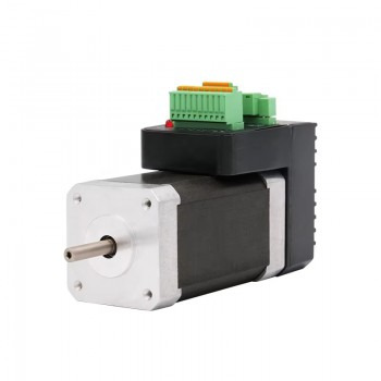
Performance characteristics and applications of bipolar stepper motors
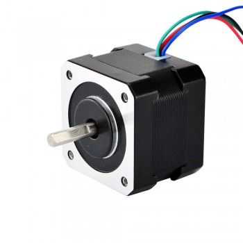
1.Basic structure of bipolar stepper motors The basic structure of bipolar stepper motors includes three parts: stator, rotor and winding. The stator is the stationary part of the motor, usually composed of multiple stator teeth, each of which is wound with two-phase bipolar windings, namely A-phase winding and B-phase winding. The A-phase winding is wound from stator tooth 1 and then wound on stator teeth 3, 5, and 7 in sequence, where stator teeth 1 and 5 have the same winding direction, and stator teeth 3 and 7 have the same winding direction. The B-phase winding is also wound on the same principle, where stator teeth 4 and 8 are a group, and stator teeth 2 and 6 are a group.
2.Working principle of bipolar stepper motors The working principle of bipolar stepper motors is based on the interaction between electromagnetic fields and permanent magnets. When current passes through the electromagnet on the stator, a magnetic field is generated, which attracts the poles on the rotor and causes it to rotate. As the direction of the current changes, the rotor will continue to rotate until it encounters external resistance. Specifically, each winding of a bipolar stepper motor can be energized in two directions, so one end of each winding can be either N-pole or S-pole. This design makes the bipolar stepper motor more flexible in control mode, and can achieve more precise position control and higher dynamic performance.
3.Performance characteristics of bipolar stepper motors 1.High-precision positioning: Bipolar stepper motors use stepping technology, and each step position is very accurate, which can accurately locate the required position. This high-precision positioning feature gives bipolar stepper motors obvious advantages in situations where precise position control is required. 2.Strong reversibility: Bipolar stepper motors have two independent coils, and the direction of the current in the coils can be changed to achieve forward and reverse rotation of the motor. This strong reversibility makes bipolar stepper motors very adaptable in situations where the direction of the motor needs to be changed frequently. 3.Large static torque: Bipolar stepper motors can also provide high torque output in a stationary state, which allows them to withstand various loads and provide good starting power when they start to rotate. This characteristic of large static torque makes bipolar stepper motors have good application prospects in occasions where they need to bear large loads. 4.Sensitive dynamic response: Bipolar stepper motors have a fast dynamic response speed and can quickly adjust the control amount to cope with system changes. This makes bipolar stepper motors have good application effects in occasions that require fast response. 5.High control accuracy: The speed and angle of bipolar stepper motors can be accurately adjusted according to the size and frequency of the control signal. This high control accuracy makes bipolar stepper motors have good application effects in occasions that require high-precision control. 6.Simple design: Compared with other types of motors, bipolar stepper motors are also very easy to design and manufacture due to the simplicity of their working principles and easy control.
4.Application of bipolar stepper motors 1.Medical equipment: Bipolar stepper motors have important applications in medical equipment. Due to their miniaturization and high precision, they can be precisely controlled in the body and support high-level operations in medicine and surgery. 2.Chemical Industry: In the field of chemical industry, bipolar stepper motors are used for the control of powders and liquids. Their precise control and high efficiency make their application in the subtle field more prominent. 3.Instrumentation: In the field of instrumentation, bipolar stepper motors are mainly used for flow control in pipelines and the regulation of moving powders in the production process to ensure precise measurement and control. 4.Industrial Automation: Bipolar stepper motors are widely used in industrial automation equipment, robots, CNC machine tools, textile machinery and other fields. It can provide precise position control and reliable operating performance, and is suitable for occasions requiring high precision and fast response. 5.Computer Peripherals: In computer peripherals such as printers and scanners, bipolar stepper motors are used for precise position control and fast response speed. 6.Photography and Filmmaking: Bipolar stepper motors are also used in photography and filmmaking, where precise control is required.
Similar articles:https://plaza.rakuten.co.jp/yixing/
0 notes
Text
How hybrid stepper motors reduce the risk of failure
1.Basic principles of hybrid stepper motors The hybrid stepper motor is designed by combining the advantages of permanent magnet and reactive stepper motors. Its rotor itself is magnetic, so the torque generated at the same stator current is greater than that of the reactive stepper motor, and the step angle is usually smaller. This design makes the hybrid stepper motor perform well in high-precision control.
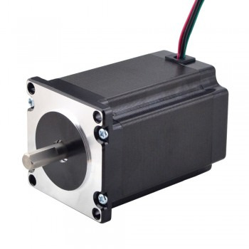
2.Design structure of hybrid stepper motor 1.Stator: The stator is the fixed part of the motor, usually stacked with silicon steel sheets. There are multiple coils wound on the stator to generate a magnetic field. The shape and size of the stator have a great influence on the performance of the motor. 2.Rotor: The rotor is the rotating part of the motor, usually made of permanent magnet material. There are also multiple poles on the rotor, which attract and repel the poles on the stator to generate a rotational torque. The design of the rotor makes the motor produce a greater torque than the reactive stepper motor at the same stator current. 3.Rotor shaft: The component that connects the rotor and the load, usually made of high-strength materials to withstand large torque. 4.Bearing: The component that supports the rotor shaft, which can reduce friction and wear and increase the life of the motor. 5.End cover: The component that protects the internal components of the motor, usually made of metal or plastic.
3.Methods to reduce the risk of failure of hybrid stepper motors 1.Select the right load and driver: Selecting the right load can effectively reduce the resonance phenomenon and prevent the motor from losing steps. If the load inertia is too large, you can consider distributing it to multiple axes or using a reducer to reduce the load inertia. At the same time, make sure that the driver used matches the motor, can provide sufficient current and work stably. 2.Adjust the motor control parameters: By adjusting the motor control parameters, such as acceleration, speed, step angle, subdivision number, etc., the occurrence of resonance, loss of step and noise can be effectively reduced. It is recommended to adjust according to the actual situation to avoid excessive adjustment and other problems. 3.Install dampers and radiators: Installing dampers can effectively reduce the occurrence of resonance and improve the stability of the motor. Installing radiators can effectively reduce the temperature of the motor, avoid overheating, and improve the stability of the motor. 4.Control the motor running time and ambient temperature: Control the motor running time to avoid overheating caused by long-term high-speed operation. At the same time, control the ambient temperature and choose a suitable installation location to avoid the impact of high temperature environment on the motor. 5.Use a stable power supply: Using a stable power supply can avoid the impact of voltage fluctuations on the motor, thereby reducing the possibility of motor jitter. 6.Optimize the acceleration and deceleration curve: During dynamic movement, optimizing the acceleration and deceleration curve can reduce load jitter and improve the stability and service life of the motor. 7.Improve electrical wiring: Try to keep the distance between the control signal and the high current load line or the impact load line. If the electromagnetic environment is particularly harsh, try to use shielded wires or twisted pairs for the control signal line. 8.Choose a stepper driver with sine wave control: If you cannot avoid the natural vibration frequency speed range, try to choose a stepper driver with sine wave control to reduce vibration and noise.

4.Design requirements for hybrid stepper motors 1.Step angle design: The step angle design of a hybrid stepper motor is one of the key parameters. The smaller the step angle, the higher the precision of the motor. Common step angle designs include two-phase, three-phase and five-phase, among which the two-phase step angle is generally 1.8 degrees, the three-phase step angle is generally 1.2 degrees, and the five-phase step angle is generally 0.72 degrees. 2.Subdivision drive design: Subdivision drive technology can achieve step angle subdivision by controlling the current in the stator winding so that the synthetic magnetic field inside the stepper motor changes according to certain requirements. This method can reduce the step angle, improve resolution, reduce low-frequency vibration, and make the motor run more smoothly and evenly. 3.Torque design: The rotor of the hybrid stepper motor is magnetic, so the torque generated under the same stator current is greater than that of the reactive stepper motor, and the step angle is usually smaller. This makes the hybrid stepper motor have better application prospects in situations requiring high precision and high torque. 4.Material selection: Hybrid stepper motors usually use rare earth permanent magnet materials with high magnetic density characteristics as rotor magnets to ensure the high performance and stability of the motor. In addition, the material selection of the motor is also very important. For example, the use of high-temperature resistant permanent magnets and high-quality cold-rolled steel sheets can improve the performance and life of the motor. 5.Structural optimization: The structural optimization of the hybrid stepper motor includes the symmetric design of the stator winding, the neglect of magnetic saturation, eddy current and core loss, and the dynamic response process of the excitation current. These optimization measures can ensure the stability and efficiency of the motor during operation.
Source:https://community.networkofcare.org/blogs/amber_stepper_motor/archive/2024/11/14/how-hybrid-stepper-motors-reduce-the-risk-of-failure.aspx
0 notes
Text
Classification and technical characteristics of servo motors
1.Definition of servo motors A servo motor is an engine that controls the operation of mechanical components in a servo system. It is an auxiliary motor indirect speed change device. The servo motor can control the speed and position accuracy very accurately, and can convert the voltage signal into torque and speed to drive the control object. The rotor speed of the servo motor is controlled by the input signal and can respond quickly. In the automatic control system, it is used as an actuator, and has the characteristics of small electromechanical time constant, high linearity, and starting voltage. It can convert the received electrical signal into angular displacement or angular velocity output on the motor shaft.

2.Classification of servo motors 1.DC servo motor The DC servo motor is the earliest servo motor. It is powered by a DC power supply and can achieve precise control of the motor by controlling the current size and direction. It has high speed and torque, fast response speed, and high control accuracy. It is suitable for industrial automation fields with high-precision control, such as CNC machine tools, printing machines, packaging machines, etc. However, due to the presence of brushes and brush rings in DC servo motors, long-term operation may cause brush wear, affecting the performance and life of the motor. 2.AC servo motor The AC servo motor is powered by an AC power supply and has a high speed and torque. It uses the principle of electromagnetic induction to convert electrical energy into mechanical energy and achieves precise control through pulse signals. The AC servo motor has a simple structure, brushless commutation, and long life. It is suitable for fields with high-precision control and high-power output, such as wind turbines, ship power systems, rail transportation, etc. In addition, the AC servo motor also has good dynamic performance and anti-interference ability, which can meet the working requirements in various complex environments. 3.Brushless servo motor The brushless servo motor is a motor without brushes and brush rings, and the current and torque are controlled by an electronic controller. It has the characteristics of high efficiency, high reliability and long life, and is suitable for application scenarios that require high precision and long-term operation. Brushless servo motors are widely used in robots, automation equipment, medical equipment and other fields.
3.Technical characteristics of servo motors 1.High precision The servo motor adopts advanced closed-loop control technology, and the encoder provides real-time feedback of the motor's position and speed information to achieve precise control. Its positioning accuracy can reach 0.001mm, or even higher, and is suitable for occasions with extremely high position accuracy requirements. 2.High response speed Servo motors have fast response capabilities and can reach the target position and speed in a very short time. This makes it have significant advantages in situations where high-speed and high-precision motion is required. 3.Good stability Servo motors use advanced control algorithms and drive technologies to maintain stable operating performance in various complex environments. At the same time, they have strong anti-interference capabilities and can effectively resist external interference and noise. 4.High flexibility Servo motors can be customized according to actual needs to meet the needs of different applications. In addition, it supports multiple control modes, such as position control, speed control, and torque control. 5.Other technical features Servo motors also have the characteristics of high efficiency, low noise, and low heat generation. Its high efficiency is reflected in the ability to convert more electrical energy into mechanical energy and reduce energy waste; low noise and low heat generation make it quieter and more comfortable during operation.
4.Methods for increasing the speed of servo motors 1.Adjust the feedback signal The speed control of servo motors can be achieved through feedback signals, such as position feedback, encoders, etc. When the servo motor speed is low, the parameters of the feedback mechanism can be adjusted appropriately, such as increasing the resolution of the encoder or increasing the number of encoder lines, so as to improve the feedback accuracy of the servo motor and thus increase the speed. 2.Increase the voltage Increasing the voltage is one of the important ways to increase the speed of the servo motor. The higher the voltage, the corresponding current will also increase, which will cause the motor to output greater torque, thereby increasing the speed. However, while increasing the voltage, it is necessary to pay attention to controlling the temperature of the motor to avoid damage caused by overheating. 3.Optimize the control parameters Optimizing the control parameters of the servo motor can also increase the speed. When optimizing the control parameters, it is necessary to consider factors such as the parameters of the feedback link, the parameters of the feedforward link, and the response speed of the controller, and conduct system analysis and simulation verification to finally obtain reasonable control parameters. 4.Replace the high-speed motor If a higher speed is required, it can be achieved by directly replacing the high-speed servo motor. The high-speed servo motor is more sophisticated in design and can withstand higher speeds and loads, thereby achieving higher control accuracy and speed requirements. 5.Increase the mechanical reduction ratio When the speed of the high-speed servo motor has reached the upper limit, a higher speed can be achieved by increasing the mechanical reduction ratio. The mechanical reduction ratio can be achieved by using mechanical elements such as gears, belts and couplings of different specifications. However, it should be noted that increasing the mechanical reduction ratio will reduce the output torque of the motor.
Source:https://community.networkofcare.org/blogs/amber_stepper_motor/archive/2024/10/26/classification-and-technical-characteristics-of-servo-motors.aspx
1 note
·
View note