
Last Seen Blogs

flying850605
멋진세상

loadingmw278
Untitled

unlila
Bassroom

saltylemon00
What Am I Doing With My Life

velthurvik
velthurvik


Text
𝐓𝐑𝐀𝐍𝐒𝐌𝐈𝐒𝐒𝐈𝐎𝐍 𝐋𝐈𝐍𝐄𝐒
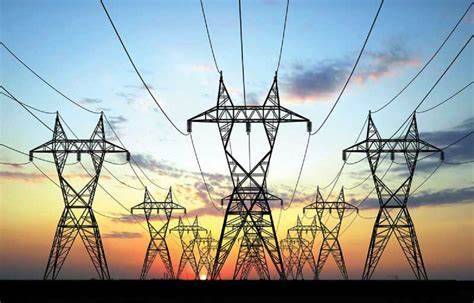
A transmission line is an essential component of the electrical power system that transfers electrical energy from the power source to the load. It is a type of high voltage power cable that is used to transmit large amounts of power over long distances. Transmission lines are critical to the functioning of the electrical grid as they help in maintaining the reliability and stability of the system.
The basic structure of a transmission line consists of three components – conductors, insulators, and supporting structures. The conductors are made of aluminum or copper and are arranged in a specific configuration to minimize the losses due to resistance. The insulators are used to support the conductors and provide insulation between them and the supporting structures. The supporting structures, usually made of steel or concrete, provide the necessary mechanical strength to hold the conductors in place.
One of the critical parameters that define the performance of a transmission line is its impedance. The impedance of a transmission line is the ratio of the voltage drop across the line to the current flowing through it. The impedance of a transmission line depends on several factors such as the length of the line, the type of conductor used, the frequency of operation, and the distance between the conductors. A transmission line with low impedance has a higher power transfer capability and lower losses.
Transmission lines are classified based on the voltage level they operate at. Extra high voltage (EHV) transmission lines are used to transmit power over long distances at voltages exceeding 230 kV. High voltage (HV) transmission lines are used to transmit power over shorter distances at voltages ranging from 66 kV to 230 kV. Medium voltage (MV) transmission lines are used for local distribution of power at voltages ranging from 1 kV to 69 kV.
One of the primary challenges associated with the transmission of electrical power is the losses that occur due to various factors such as resistance, capacitance, and inductance of the transmission line. These losses can result in a significant reduction in the efficiency of the power system. To overcome this problem, advanced technologies such as High Voltage Direct Current (HVDC) transmission have been developed that can transmit power over long distances with lower losses.
In conclusion, transmission lines are critical components of the electrical power system that help in the efficient transmission of electrical energy over long distances. With advancements in technology, the performance and efficiency of transmission lines have improved significantly, resulting in a more reliable and stable power grid. As the demand for electrical power continues to grow, transmission lines will play an increasingly important role in meeting the energy needs of the world.
Transmission lines are also vulnerable to various external factors such as lightning strikes, high winds, ice, and other extreme weather conditions, which can cause significant damage to the lines and interrupt the power supply. To mitigate these risks, transmission lines are designed and constructed to withstand these external factors.

Benefits:
Entire transmission system can be simplified to a two port network for the sake of easier calculations
The behavior of transmission lines and its voltage and current under normal and abnormal conditions depends on A, B, C, D, Z and H parameters
Transmission line parameter simplifies the model and gives quite accurate result
Load flow study in transmission line
Analyzing protection schemes
Increase the system efficiency
Avoide any danger in complete system.
How we get electriciy through transmission lines .
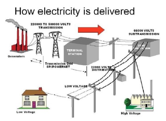
Electricity is generated at power plants and then transmitted over long distances through transmission lines to reach the load centers where it is needed. The electricity generated is usually in the form of high-voltage alternating current (AC) or direct current (DC).
In an AC transmission system, the electricity generated at the power plant is first stepped up to high voltage levels using transformers. The high-voltage AC power is then transmitted over long distances through transmission lines to the load centers where it is required. At the load centers, the voltage is stepped down to the required levels using transformers, and the electricity is distributed to the consumers.
In a DC transmission system, the electricity generated at the power plant is first converted to high-voltage direct current using a converter station. The high-voltage DC power is then transmitted over long distances through transmission lines to the load centers where it is needed. At the load centers, the DC power is converted back to AC using an inverter station, and the electricity is distributed to the consumers.
The transmission lines are made of high conductivity materials such as copper or aluminum, which have low resistance, to minimize the losses due to resistance and capacitance during transmission. The conductors used in transmission lines are often bundled together or arranged in a specific geometry to reduce the distance between them and to minimize the losses due to capacitance.
The electricity transmitted over the transmission lines can experience losses due to various factors such as resistance, capacitance, and inductance. These losses can cause a reduction in the efficiency of the power system and result in significant power wastage.
To minimize these losses, the transmission lines are designed to operate at high voltages and to have low resistance, low capacitance, and low inductance. The transmission lines are also designed to withstand various external factors such as high winds, ice, and lightning strikes.
In conclusion, electricity is transmitted over long distances through transmission lines from the power plants to the load centers where it is needed. The transmission lines are designed to minimize losses and to withstand various external factors. The efficient operation of the transmission lines is critical to the reliability and stability of the electrical power system.
1 note
·
View note
Text

𝐑𝐢𝐧𝐠 𝐌𝐨𝐝𝐮𝐥𝐚𝐭𝐨𝐫

A ring modulator is a circuit which was originally employed in telecommunications systems for the modulation and detection of transmission signals. More recently however, the ring modulator has found an interesting application in the field of electronic music and is in fact now a common feature in many synthesisers.
In electronics, ring modulation is a signal processing function, an implementation of frequency mixing, in which two signals are combined to yield an output signal. One signal, called the carrier, is typically a sine wave or another simple waveform; the other signal is typically more complicated and is called the input or the modulator signal. A ring modulator is an electronic device for ring modulation. A ring modulator may be used in music synthesizers and as an effects unit. A ring modulator can be used to generate a double-sideband suppressed-carrier (DSB-SC) wave used in radio transmission.
Ring modulators are electronic circuits stemming from early telephony. They are at the essence of the possibility to send and receive many simultaneous telephone conversations through one and the same couple of wires. Soon enough the circuit has found abundant applications throughout 20th century music production and performance. They are fundamental also to the working of radio receivers and emitters, both for AM and FM. The historical passive ring modulator circuit looks like this:
There are two inputs and a single output. The two signals get multiplied in the germanium diode-ring configuration between the two transformers. Input signals for this circuit must be kept smaller than 25 mV. That's why there are four resistors in the circuit. Their value must be calculated such that they are larger then the conducting resistance of the diodes used under voltage conditions specified. The diodes must be matched within fractions of a percent. The ideal transformers for this circuit must be of the toroidal type and extremely well balanced. Hard to find for audio applications but if you are lucky you can every so often recycle them from old professional audio equipment stemming from physics labs or electronic music studios. It should be noted, that the very first circuits, used vacuum tube diodes instead of solid state germanium of silicon diodes as drawn here. Amongst electronics and music afficionados on the internet, transformer based circuits as well as designs using vacuum tubes. still seem to have followers, generally synth players and e-guitarists with a popular music background. The ringmodulator still seems to have quite some popularity there. The number of forums we could find is pretty elevated. Things such as the kind of diodes to be used (germanium, vacuum tube, Shottky, XOR-circuits) lead to ongoing lengthy discussions. Ringmodulators of all kinds can readily be found on the market. The Moog model has been quite popular for a long time.
A ring modulator is basically a four quadrant multiplier, that is to say, a circuit which will multiply two input voltages, regardless of whether they are positive or negative and ensure that the product voltage is of the correct po larity. Thus a positive voltage multiplied by a negative voltage will yield a negative voltage, a negative voltage times a negative voltage will give a positive voltage, and so on.
The question is: why is such a circuit of interest to the electronic music enthusi ast? The answer can be found by com sidering the following mathematical expression for the product of two sinewaves:

sin a sin = cos (a-)-15 cos (a+). Since a cosine is simply a sinewave with a 90° phase shift, it can be seen that multiplying two sinewaves results in two new sinewave signals whose frequencies are the sum and difference respectively of the two original signals. Note that this is only true for sinewave signals and not for other types of waveform. However the same effect will be produced by com- binations of sinewaves. Thus, for example, if a combination of two sinewaves is multiplied with a third sinewave, each of the constituent sinewaves in the original signal will produce its 'own' sum and difference products. The multiplication of two sinewave input signals is illustrated in the oscilloscope photo of figure 1. The sinewave of the upper trace is multiplied with a second sinewave of higher fre- quency to produce the product waveform shown on the lower trace.
It's usefullness for the performance of new music scores in general is not evident, as it is designed with a built-in LFO and carrier frequency generator. The foot-switch also, reveals the origin of the device as a guitar effect pedalI. we use the ringmodulator to multiply two signals in the ultrasonic audio range and if their difference tone falls in the audio band, then we can use it to detect just this difference tone as the co-existent sum tone a fortiori will be out of the audio range.As soon as electronic music studios started rising up in the beginning of the fifties of the 20th century, the ringmodulator became a standard component for the production of electronic music. Early composers that made extensive use of them are Karlheinz Stockhausen (Telemusik, Mantra, Hymnen, Mixtur...), Wladimir Ussachewsky, Gordon Mumma, John Cage, Allan Strange, Alvin Curran... The analog electronic synthesizers as they were build since the seventies, almost all contained at least one patchable ringmodulator (Synket, Putney of VCS3, EMS, Korg, R.Moog, ARP, D.Buchla, Synthelog, Serge etc).

Even in some orchestral compositions one may encounter requests for ringmodulators, for instance the Flemish composer Luc Brewaeys uses them in 'Trajet' and 'Due Cose'. The ringmodulator circuits for these performances were designed and made by us, together with some software to generate the signals to be used as modulators for the orchestra sounds on the inputs. At the time these pieces were written, it was already no longer common usage to use spare sinewave generators to this purpose. MIDI-controlled modular synths could perfectly replace the sinewave generators. Nowadays, the entire setup can be replaced with a simple computer program, a 'patch'.
Ringmodulators seen from the perspective of historical performance practice, make us think about the differences between period-circuits versus modern (software based) alternatives.
Other than in the case of tape-recorders, here the physical appearence on stage of the ringmodulator has no importance at all. It can take just about any shape. Most often it's just a metal box with some audio connectors and at the most, a few potentiometers to set levels. The musical result though may turn out very different, for one or more of the following reasons:
1)analog ringmodulators 'suffer' a lot from leakage: that is, feed-through of the original inputs to the output. Most of the time, there is a noticable difference in leak-through, between the one input and the other. That's why inputs are often labeled 'signal' and 'carrier', or anything similar to make the distinction.
2)analog ringmodulators have a very limited signal to noise ratio
3) analog ringmodulators may distort the signal in quite some other ways than what is to be expected from the multiplication process on itself. The dynamic range of the device is inherently limited. The reason is simple: if we multiply two signals with their maximum allowable level, say 10, then the amplitude range of the output ought to cope with the product, say 100 in our example. This inherent -20dB reduction can be compensated for, but always at the detriment of signal-noise ration. This remark, by the way, also lies in full to the digital implementation. However in a digital implementation, we can often anticipate and provide in a much higher bit-resolution at least for the input and modulator signals.
3 notes
·
View notes