
Don't wanna be here? Send us removal request.
Statistics
We looked inside some of the posts by ciara-maker-portfolio-blog and here's what we found interesting.
Average Info
Notes Per Post
0
Likes Per Post
0
Reblog Per Post
0
Reply Per Post
0
Time Between Posts
14 days
Number of Posts By Type
Text
17
Last Seen Tumblr Blogs


Fun Fact
In 2020, 27% of US Tumblr users had an annual household income of over $100,000.
Text
Design Review Update
I have encountered a couple of challenges in this project, such as my prototyping not turning out how I thought it would. My first attempt at a prototype was to print all of my boxes at their full size and then adjust from there, but after the first couple of boxes got halfway through and failed, I realized that it was a massive waste of time and material. I instead decided to move on to making a cardboard prototype.

I 3D printed stoppers for the metal pole supports that I glued into the bottom of the cardboard pots, but this proved to be an unsuccessful way to prototype, as when I put the poles in, the stoppers fell out. I am modifying my next prototype and final project to have the supports 3D printed and attached to the pots to avoid this next time, and am going to print a scaled down model of my final project.
Much of my feedback was to work on my project quicker, which I will accomplish by making my print files outside of class. I am also planning on incorporating circuitry and LEDs to make a light with button system to keep track of the days you water the plants.
I am mainly using the 3D printer and building on my Rhino skills with much more complex builds, and have also used the laser cutter in this prototype for my one failed prototype of cardboard.
I have used the engineering and design process multiple times during this process, particularly circling back to “improve” in my prototyping process. I saw a problem of urban gardening, and decided to make a project that would better that, and with each prototype, my project is getting more and more usable.
I have not particularly well kept up with my schedule, mainly because I didn’t realize how long the prototypes would take to print, or that I would need to switch types of prototypes. I will try to rev up my work quantity over the next couple of weeks to accommodate for this and finish on time.
0 notes
Text
Gallery Response
One of my favorite pieces from the gallery was Gina Marcel’s E-textile dress. I saw that she used a Flora board to power the LEDs on her dress, which was very cool as I was working with Flora at the same time. I really liked how she incorporated the adorable embroidery on the dress with lights to match the images, such as a yellow LED in the embroidered sun and a red one on the girl’s red polka-dot dress. It struck a good balance between being electronic and design work, which was really nice. I thought that the lights were not overpowering as they would have been if she used a bunch of them, but rather enhanced the embroidery on the dress. I also liked how the images on the small dress could represent somebody wearing the dress, as it is a little girl in a field of flowers, and the embroidery is on a little girl’s dress. In terms of the troubleshooting for this project, I think the most time was spent on the Flora code and getting it to function properly with the switch on the dress.
Another piece that I really liked was Jaymes Dec’s Infinte Labrynth. I really liked the layering that he used in his piece by using a mirror in the back to increase the depth of his piece, as well as colored and rastered acrylic to get the look of a maze. I also liked how the illumination at the bottom changed colors, so the labrynth had different shades within it. I would ask this artist how he narrowed down which materials to use for this project, and how he decided to assemble it. I am also curious as to how many prototypes he went through in this project, as it seems like it would be a challenge to place the lighting at the bottom in just the right spot for the desired effect. This project uses a really interesting mix of electronics via the light strip at the bottom, and art via the scoring of the labrynth and assembly of the box. This project made me look at materials that we use in a different way, because I would not think to use acrylic and lights as an optical illusion.
I also really liked the Jabberwocky reading image. I think it’s amazing how this artist incorporated LEDs, the reading piece at the top, and what I think is a hand-drawn image all into one. It is a very cool interpretation of a poem, and I think that it must have been very hard to coordinate the LEDs to light up at the right point in the story to make sense! I think that this artist spent the most time troubleshooting with that, getting the timing perfectly so that the LEDs make sense with the part of the story that is being read at the top of the screen. If I met this artist, I would ask them how they navigated the coding for this, as it seems like it would be super complex to me. This piece made me think a little bit more out of the box in terms of project inspiration, because I never thought that an electronic art project could be based off of a text! This artist also built a really cool cardboard and 3D-printed frame around their illustration, which makes it look like a piece of art that could be hanging up in a museum.
0 notes
Text
Wearable Final Reflection
My process for making this project was quite difficult. In the initial building stage of this project, putting together the circuit was not tough at all. I was able to assemble it very quickly in comparison to the rest of my project. The coding for this project took me a long time. Initially, I was able to upload my code to the board and it would flash through each image before showing a frowny face. I went through troubleshooting the code for about a month, downloading libraries, looking through forums, and editing the code, but nothing worked. I eventually posted in the Adafruit forum, and Carter, who works for Adafruit, got back to me and pointed out an issue that I didn’t even know I had: I had to have 3 tabs open at once when uploading the code, as things in the two other tabs were being called in the original code that weren’t being defined without the other tabs.


After finishing troubleshooting the uploading portion of the code, I faced another problem: the correspondence of code to matrix pin position. In some columns of the matrix, the numbers went from 0-7 downward, and in others 0-7 upward, so I had to figure out which columns went which way in order to code it right. I ended up coding per individual pixel instead of “drawing lines” on the matrix, which would have been much faster, but this worked just as well after figuring out what was going wrong. Curiously, though, this issue did not occur with my Christmas tree, only with the bow and the gift box.

My final product turned out quite well. I wasn’t able to quilt the whole blanket as I had planned because I lost all of my quilting materials, but I was able to improvise with a blanket I had at home and a pocket I had already made for the matrix. If I had to pick one thing to improve on this project, I would work on finding a smaller power source than my computer, preferably one that could just stick on the back of the circuit into the pocket for the matrix. I am happy that my project began to work with the Bluetooth connection about a week before it was due, and I learned a lot in this process about coding, troubleshooting, and asking experts for help.


0 notes
Text
Prototype 1 Reflection
So far in my process, I have completed the code for my matrix and I have soldered the pieces of the project together. I used the instructions on the Adafruit website (https://learn.adafruit.com/neopixel-matrix-snowflake-sweater?view=all) to assemble the matrix, flora, and flora BLE pieces so that my assembly would look the same as theirs.
Coding wise, I looked at the screenshots of light patterns that Becky wanted to light up in her matrix, which she linked in the Adafruit tutorial. I compared this to the code for the matrix to figure out how to code for my own shapes to light up on the matrix. I planned out my own shapes in photoshop the same way that Becky did for her snowflakes, and I coded the lines and individual matrix lights that would be lit up in each of these as I had learned from looking at the original code. I coded for a Christmas tree, a gift box, and a bow, as seen below.

The white spaces are what I wanted to be lit up on the matrix, so I coded for the lines and points of the matrix that would need to be lit up. I learned that the matrix starts at the point (0,0) in the top corner, rather than (1,1), so this was good to know before beginning my coding, as all of my numbers would have been off otherwise.

I commented out what shape each part of the code worked for, so if I need to fix anything, I know where to look.
I am currently not facing any challenges in my design process other than thinking of an additional Christmas image to include in my matrix.
As far as feedback, I would like to hear thoughts on what other shapes I could code for, as well as the designs that I should include on the material part of the quilt, as well as coloring.
0 notes
Text
Wearables Schedule
11/29 - Coding for matrix (1 hour)
11/30 - Coding for matrix (1 hour)
12/4 - Before Class: 30 mins coding. Coding for matrix (1 hour)
12/5 - Before Class: 30 mins coding. Coding for matrix (1 hour)
12/6 - Before class: 1 hour coding. Coding for matrix (1 hour)
12/8 - Before class: 1 hour coding. Design outer squares for quilt (1 hour)
12/11 - Before class: 20 mins sewing. Sew squares together & design them (1 hour)
12/13 - Sew squares together and finish project (1 hour)
0 notes
Text
Microcontroller Exploration
I am definitely intending to incorporate light into my project. I plan on using an 8x8 neopixel matrix from adafruit as my lights. I will test the light code on a rigid matrix that we already have, and for the final project I will either use the flexible one or charlieplex multiple color-changing LEDs, which I am in the process of looking up. This is the only electronic component that I am planning on using, but it will work well with the flora board and bluetooth connection to the app, which will make the changing of the lights really special. I will also be using stamps, fabric, thread, and a sewing machine for design and assembly of my quilt. If I am using the matrix, I do not think that I will need to multithread, but if I need to use LEDs, I may, but I will also be charlieplexing.
Charlieplexing is threading together multiple LEDs using a limited number of pins, and getting the LEDs to light up by alternating which pin is sending out electric signals and which one is ground. This will be useful if I cannot use a matrix in my project, as it will limit the number of pins that I am using on my board and make the LED chain more matrix-like.
Below is the link to the code that Becky Stern used for her bluetooth sweater: https://learn.adafruit.com/neopixel-matrix-snowflake-sweater?view=all
I am modifying this code by changing the pixels that will light up. I will be altering the portion of the code that creates the pattern of each snowflake, and changing it to make various holiday shapes, such as a christmas tree, snowflake, gift box, star, etc.
Below is the code for charlieplexing the arduino board: http://www.instructables.com/id/Charlieplexing-the-Arduino/
I can modify this code to work for my flora board, and also to include more pins and LEDs if I need to. This will help me customize the LEDs that are lighting up, if I am not able to use a matrix in my project.
0 notes
Text
Wearables Brainstorming
For my wearables project, I have found two projects that I really like and would love to emulate for my own project.
The first project is the light up Bluetooth snowflake sweater. This sweater uses the flora microcontroller and a paired Bluetooth app to make the LED board flash in different colors and patterns. If I was going to adapt this project and make it my own, I would change the code to flash in different patterns from just snowflakes, maybe incorporating other holiday images that they could flash in. I would lay this circuit board inside a sweater with a pattern (like a Christmas tree) already knitted into the pattern of it, so there would be lit up holiday imagery and basic imagery.

The other project that I had an idea for would be a quilt with the middle piece as a wearable. I would include LEDs flashing in the patterns of various holiday images in the middle piece, as well as possibly a speaker playing a Christmas song. This would use the flora microcontroller as well, and the same app. The surrounding pieces of the quilt would not be wearables, but rather covered in other holiday images and messages to tie together the holiday theme.

The first project that inspired these were the Bluetooth microcontroller snowflake sweater by Becky Stern. She uses the Bluetooth app to make the sweater light up in different arrays of snowflakes, which I really liked and would like to include the idea of in my project.
The second project that inspired these was the Starry Night prom dress that a teenager made. She included LEDs in her prom dress to make it light up like the night sky, which I thought was beautiful. I liked the twinkling setting that she had on her dress, and would like to incorporate this in my design as well.
Materials-wise, I would be buying my own sweater for the first project, and would need color-changing LEDs, a flora microcontroller, and resistors and batteries. For the second project, I would need different scraps of material (which I may be able to bring in from home), various stamps and paints, color-changing LEDs, a needle and thread, a flora controller, and resistors and batteries.
Prom dress: https://www.hackster.io/Maddy/starry-night-prom-2eb206
Bluetooth Sweater: https://www.youtube.com/watch?v=0_UgyBGbRIQ&feature=share
Pinterest board: https://www.pinterest.com/csantry3200/wearables-project-inspiration/
0 notes


Text
Ultimaker Progress Update 10/13
Today I came in during my free to finish assembling prototype 1.5 and worked on prototype 2 during class. Prototype 1.5 ended up fitting together very well, but I quickly realized that the supports that I added for this prototype to keep the waves straight up and down are too tight on the dowels, so they wouldn’t move up and down well. For my second prototype, I made the holes in the supports wider so that the dowels could move up and down easily and so that the wires for the lights, but still narrow enough that they will hold the dowels straight up and down.

In my 1.5 prototype, it looks like the lid to my box is too small for the sides of the box, but it is actually the right size because the joints that I am using on my prototype 2 and final boxes are different. I am using the same joints that we used last year on the synthesizer on my final product, and I will use them on my second prototype as well.
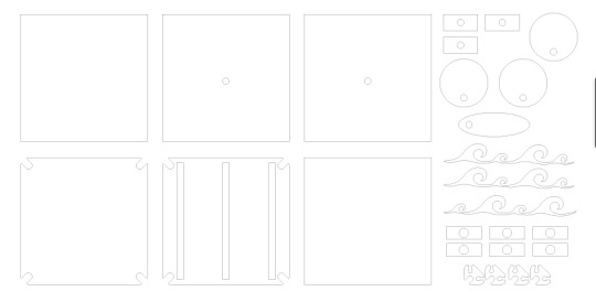
This is the file that I used to cut my second prototype. I cut my second prototype during class today and am going to assemble it tomorrow during class. I also plan on cutting my final product during class tomorrow and then assembling it during my free on Wednesday.
I also need to allow time for assembling my light string. I think that I will be able to get this done during my free on Wednesday as well. I also realized when I cut my second prototype that I haven’t included a hole for the button to turn the lights on and off in any of my prototypes, so I will need to include this in my final product.
So far, this product has been extremely manufacturable. All of the materials that I have needed for my project have been readily available in the lab, and I think that this project would be pretty implementable in the real world.
0 notes
Text
Ultimaker Progress Update 10/12
Today in class I worked on finishing my first prototype. I assembled my box by adding the waves to the box and inserting them in the CAM portion of the box.

Once I put in the waves, I realized that the CAM motion would not work unless I put stoppers underneath the waves and the lid of the box to both stabilize the waves and keep them in the same location in the box. Once I realized that I needed to add these, I went back into illustrator to edit my file and put in all of the aspects of my box that I was missing in my first prototype. I decided to do a prototype 1.5 made out of cardboard in order to get the measurements of the box really accurate before I move onto wood or the final product.

In illustrator, I added a hole to another side of the box, three slits on the top of the box, and six stabilizers that I can layer under the lid in my 1.5 prototype.
I think it was really important for me to make these mistakes in my first prototype because it helped me to realize all of the components that I need in this box in order to make it work. I definitely think that it made me more conscious of what I am doing and how accurately I am doing it. I also think that because I have been thrown off of my timeline, I am realizing now that budgeting my time so tightly was not a great idea. For my next project, I will need to allow for more time at each step.
After altering my illustrator file, I ran it in the laser cutter two times in order for it to cut all the way through the cardboard. I then assembled the sides of my box.

I am planning on coming in tomorrow (10/13) during my free to get closer to on schedule, and hopefully, I will be able to cut my second prototype tomorrow. This product has become more complex as it has gone on, and I look forward to more challenges that it will bring me.
0 notes
Text
Ultimaker Progress Update 10/11
Today in class I worked on dry fitting my box together and re-laser cutting my waves out of cardboard. At the beginning of class, I laser cut the waves out, as they had been lost from last class. After cutting the waves out, I began to dry fit my box together with hot glue. I decided to use hot glue for my first prototype because I thought it would be easiest while still giving me a good idea of what my box will look like.

Through doing this, I realized that attaching my box together this way will cause the top piece of the box to be too small for the sides of the box and it will fall through the top opening so I will need to fit the box together with dowels so that it all fits properly.

I also hot glued the CAM motion pieces to the dowel, so that I can see how the waves will move with this process. I assembled the CAM piece pretty well, and I was pretty confident that it would work.

Once I put the CAM piece into the box, I realized that I needed to cut a hole in the back side of the box as well to stabilize the dowel. As it is in this first prototype, it is skewed higher in the front and lower in the back, and it is not as stable as I would want it to be, so in my next prototype, I will include a hole of the same height to stabilize the dowel.

I also assembled the wave CAM pieces. I attached a dowel to the bottom of each wave and then a rectabgle to the base of each dowel, so that it is easier for the skewed circles to push up on the waves.

Upon putting the waves together with the box, I realized that I forgot to cut slits in the top of the box for the waves to pop through. I then cut them with a box cutter, so that the prototype would be functional.
I also realized when assembling the box that the waves were not stable enough to move up and down without wobbling to each side. I will need to add extra supports under the lid to stabilize the waves and dowels, and they will most likely be multi-layered to keep them as upright as possible.
I will still need to come in during a free to catch up on my work, but during next class I plan on finishing up my first prototype and cutting out the second one.
0 notes
Text
Ultimaker Update 10/5
Coming into class today, I had my box file finished and my 3D design products finished. I decided to not 3D print my files because I wanted them to be up to a higher standard, but I 3D cut my box out of cardboard on the laser cutter. Cutting the box out on the laser cutter took a lot longer than I was expecting, especially getting the pieces out of the cardboard after the 3D cut. Many of the pieces had not laser cut all the way through the cardboard, so I just took a box cutter to cut them out of the cardboard. This took way longer than I was planning on taking to cut the box out, so I am falling behind on my schedule. I was planning on dry fitting my box together today, so I am planning on coming in during a free period next week to catch up on my progress.
I still think that this project will be extremely beneficial to calming people down because the CAM movement will remind people of the movement of waves on the beach, which is a very scenic image.
During next class, I plan on dry fitting my box together and testing to see if it works, and then adjusting my next prototype accordingly.
0 notes
Text
Ultimaker Progress Update 10/3
CREATE
Today in class I worked on figuring out my lighting coding for the first half of class, and making the file for my laser cut for the second half of class. I tried very hard to get my code to work with the switch and the blinking lights, but I was unsuccessful with that. I am going to keep the lights as just a switch on and off without the blinking, which I think could also be beneficial in calming people down, as there won’t be lots of blinking affecting their calm environment.
During the second half of class, I worked on the file for laser cutting my box. I made the box a cube shape with 5 inch edges. I also made the shape for the waves that will be going up and down on the CAM as well as the CAM circle pieces. I measured with calipers the diameter of the dowels that I will use on the caliper, and I made the holes in the CAM pieces this size.

At the beginning of next class, I will need to measure the diameter of the LEDs and put in holes for them in the waves.
I think that having both the CAM feature and the LEDs will really help to soothe people because watching waves crash is really calming to me, and I like the look of blue LEDs.
0 notes
Text
Ultimaker Progress Update 10/2
CREATE
In today’s class, I worked on coding for my lights again. I worked on trying to combine the switch code that I had with a switch blink code that I found online. The initial switch code worked with both turning the lights on and off, and the blink one only had the switch turning the lights on.

I was unsuccessful in putting them together. At the end of class, I tried to isolate the different parts of the combined code to find what was making the combined code not work, but I was unable to figure it out. At this point, I am considering just having the lights be constantly on because the blinking component is not working out too well. I really would like the lights to blink when the switch is turned on, but if I can’t figure it out during next class period, I will have to just settle for non-blinking lights.
The blinking lights would really help people to calm down better, but the steady lights might be better for people who get headaches or migraines from too much light action. I will work more on the coding during next class, but if I am not able to get it within the confines of my schedule, I will have to move on or work on it for homework one night.
0 notes
Text
Ultimaker Progress Update 9/27
CREATE
Today in class we worked on programming the LEDs to blink when the button is clicked, and we ran into some issues. We initially put code into the Arduino that would change which LED lit up when the button was pressed, but as soon as you lift your finger off of the button, it switches back to the original LED that was lit up.


My idea was to use the button as an on/off button for the LEDs to turn on and blink, and we executed the lights turning on and off with the button, but we did not get the blinking to work. I really want the lights to blink, because I think that that would make the piece even more relaxing, thus making it fulfill the design requirements more. I also think that the lights should blink because it would mean rising to the challenge of coding it, but if I am unable to get it to work in the next two class periods, I will just have the lights switch on and off without them blinking. Next class, I will work more on trying to get the lights to blink with the switch turning them on and off.
Going forward with the coding, I will try to combine the switch function with the blinking function as best as I can, but it could prove to be very challenging. I had hoped to finish this in today’s class, but the troubleshooting proved to take much longer than I thought it would.
0 notes
Text
Schedule
Programming
Oct 3
Work on getting switch with blinking lights (30 min)
Prototyping
Oct 3
Design box file in illustrator (30 min)
Oct 5
3D design decorative pieces for outside of box (before class)
Double check box file for vectors (before class)
Laser cut prototype out of cardboard (15 min)
Check dimensions of prototype (15 min)
Dry fit pieces together (15 min)
Oct 11
All decorative pieces 3D printed (before class)
Document prototype (10 min)
Change dimensions in illustrator for prototype 2 (15 min)
Laser cut prototype 2 out of wood (15 min)
Dry fit pieces together (15 min)
Oct 12
Due: Prototyping with complete documentation (before class)
Document prototype 2 (10 min)
Review prototyping strengths and weaknesses with class (15 min)
Laser cut final product (20 min)
Final Product
Oct 13
Due: Prototyping 2 with complete documentation (before class)
Assemble box (20 min)
Assemble light string and stick into box (20 min)
Documentation (10 min)
Oct 17
Due: Final review with complete documentation (before class)
0 notes
Text
Ultimaker Progress #3
PLAN
Today we worked on the planning phase of the creative process. For homework, we came up with sketches for three possible designs for our ideas. We also set parameters for our design and outlined a schedule for everything to be completed by.

My sketches were not big enough to see all of the detail in them, so I enlarged them in class and added more detail and annotations.


To decide on the design that I wanted to use, I evaluated all of the designs that I had with the parameters that I created for the final product and I decided on option no. 3. I think that this perfectly encompasses the parameters that I put for my project because it will be small enough to be portable and go with jthe owner wherever they go, it will be battery operated so it will be low maintenance, and it will have moving waves, which I think will be mechanical and not electronic. I may need to adjust the drawing to include a crank to make the waves move mechanically, and I think that I will be removing the requirement for sound, as it will be a lot to program for this project.
I think that going with this design will help people de-stress because the 3D designs on the side of the box will help people think of how calming the ocean is, and cranking the waves to move will help release tension. I also think that the LEDs on the waves will help to reduce stress because lights make me calmer, so I think that it will help others as well.
Going forward with this design, I think that I will need to scale down the scope of this project to make it more manageable to manufacture in the time frame that we have.
0 notes