
Don't wanna be here? Send us removal request.
Statistics
We looked inside some of the posts by deafaningphysicalcomputing and here's what we found interesting.
Average Info
Notes Per Post
0
Likes Per Post
0
Reblog Per Post
0
Reply Per Post
0
Time Between Posts
11 days
Number of Posts By Type
Text
6
Last Seen Tumblr Blogs


Fun Fact
BuzzFeed published a report claiming that Tumblr was utilized as a distribution channel for Russian agents to influence American voting habits during the 2016 presidential election in Feb 2018.
Text
Floor Crawler
As part of the experiments portfolio assignment I will be documenting the progress of constructing and coding a floor crawler bot.
Equipment used:
1 x Arduino Leonardo
1 x CNC shield
2 x Two Phase Stepper motors (Jumper Cables)
2 x 8 cm Diameter wheels
1 x 3.7 V Series Battery Tray
4 x Samsung INR18650-25R Lithium Ion Batteries
1 x Ultrasonic Rangefinder HR-SR04 w/ jumper cables
2 x Sheets Midwest White Styrene .040 x 7.6″ x 11″
4 x Strips of Sprue sourced from Games Workshop sprues
10 x Mixed size clamps
1 x Revel Contact Cement
1 x Hobby Knife
1 x Pair of Scissors
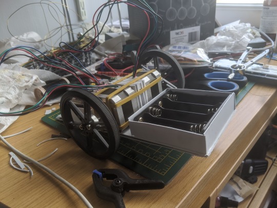
Constructing the Crawler:
Part of the challenge with building the crawler was creating a chassis capable of bearing the weight of all the components. The biggest concern was the motors, as these weighed 250g (0.55lb) each. This meant that the chassis had to bear a weight in excess of 500g (1.10lb) to hold two motors, Arduino, shield, ping sensor, battery tray and batteries.
In addition to this, suitable materials for the chassis were fairly limited. This was because they had to be large enough to form the base and stiff or sturdy enough to bear the weight. This immediately ruled out materials like card as, whilst easy to acquire in large sections, they were far too flimsy to bear the weight. The only suitable materials available were styrene plasticard and model sprue.

However, like card they were too flexible for use so had to be stiffened through engineering tricks and simple reinforcement. The first attempt got off to a poor start, as the base was far too small to hold all of the components. With this initial set back in mind, I set about creating a new, much larger one with excess room for components to be added as necessary. In order to stiffen the base a method of diagonal strips of material was used. This involved placing two strips of sprue inside the base and a series of styrene strips placed on the bottom. This massively helped stiffen the base of the crawler allowing it to bear the weight of all components on the board, without flexing excessively.

For holding everything together I used Revel Contact adhesive as this would ensure a firm bond to hold the chassis together. To ensure a flat surface and to prevent air bubbles compromising the structure by forcing the styrene apart, I used small modelling clamps to hold components down whilst the glue cured.
The next step was to create housing for the individual components with the first being the battery tray. It was formed from four pieces of styrene attached to the base with a small hole added in front of the wires where they protrude from the battery tray. This would allow the battery tray to fit snugly into the housing without needing to flex the wires over the housing.
Next was the housing for the Arduino and shield which was formed the same way as the battery tray housing. However, this was slightly higher to account for added height of the shield, with a section cut out for the cable which connects the power cables to the Arduino and Shield.
To finish the base of the crawler I added two plastic bottle caps to each end of the base. This served two purposes; to prevent the crawler from grinding wither end of it’s chassis into the floor and the other being to reduce the extremes of highs and lows that would drastically throw the sensor off. The only complication with this was that the caps proved to be unaffected by the glue, this resulted in one incident where a cap popped clean off of the chassis.
The ping sensor was the final component to be attached, after connecting the jumper cables the last problem was to attach it to the chassis facing forwards. This was done by simply blue tacking the sensor to the front.
Motors and rubber bands:
With the chassis completed it was then that the real problem of creating the crawler raised it’s head. The attachment of motors to the chassis was the biggest problem as there was no concrete method. To ensure they were even and central, several layers of styrene squares were layered together to form a sort of bracing block that would be sandwiched in between the two motors to ensure enough clearance between the wheels and the chassis. The block also featured a gap between the two sides so as to allow the wiring to go through unobstructed.
The initial method, which was really more on paper than in practice, was building a cage of styrene around the motors and then boxing them in with strips of plasticard, like door bars to keep them in. After much discussion with other people, however, the idea was ultimately scrapped.
The second method was the use of brass wire bent to form braces that would hold the motors on the chassis. However, this method was also scrapped due to the difficulty in forming a perfect fit around the motors and the realisation of a better solution.

The third and final method was the use of rubber bands as I thankfully had a small bag full of them. This was to prove the simplest and most effective method of getting the motors fixed on the chassis.

Of Code and Complications:
After the success of getting motors onto the chassis, I then encountered the next big problem of this project, programming the Arduino. Because I have not had much experience with coding an Arduino, let alone coding stepper motors, tinkering with the code proved more problematic than expected.
The easiest parts were accessing the accelStepper Library which can be found in the Arduino coder and finding code for running the echo sensor as both were online and accessed from the Arduino Forums, courtesy of Isaac100 who wrote the base code for the ping sensor to work found at https://create.arduino.cc/projecthub/Isaac100/getting-started-with-the-hc-sr04-ultrasonic-sensor-036380.
Modifying the code for the motors and the ping sensor to work together proved to incredibly finicky, the code also proved to be frustratingly temperamental with the crawler often racing in random directions. This is aptly shown in the demonstration video as the crawler appears to take on a life of it’s own.
Video of it running:
youtube
Self reflection:
Things I did well:
Built a frame that was easy to construct for fairly cheap and could bear the weight of all components easily.
Was able to work around physical issues fairly well such as attaching the motors to the chassis and work with unusual solutions such as the use plastic bottle caps as skis.
Things I could improve:
Organise the wiring so that it is less messy and less likely to interfere with the wheels. This could be done with the use of rubber bands to tie the cables together as a substitute for actual cable ties.
Spend less time on the physical aspects of the crawler and instead focus more on the coding of the crawler. This would be possible with more practice at coding and gaining a better understanding of how the code interacts.
Conclusion:
Ultimately the idea itself was almost turned into reality but suffered at the last hurdle with a major roadblock which could have been overcome with enough time and experimentation to work out the kinks in the code.
Final Code:
#include <AccelStepper.h>
// ENABLE pin, inverted #define NOT_ENABLE_PIN 8
// The X Stepper pins #define STEPPER_X_DIR_PIN 5 #define STEPPER_X_STEP_PIN 2
// The Y stepper pins #define STEPPER_Y_DIR_PIN 6 #define STEPPER_Y_STEP_PIN 3
// Define some steppers and the pins the will use AccelStepper stepperX(AccelStepper::DRIVER, STEPPER_X_STEP_PIN, STEPPER_X_DIR_PIN); AccelStepper stepperY(AccelStepper::DRIVER, STEPPER_Y_STEP_PIN, STEPPER_Y_DIR_PIN);
const int trigPin = 12; const int echoPin = 13; float duration, distance;
void setup() { pinMode(trigPin, OUTPUT); pinMode(echoPin, INPUT); Serial.begin(9600);
// Enable drivers pinMode(NOT_ENABLE_PIN, OUTPUT); digitalWrite(NOT_ENABLE_PIN, LOW);
stepperX.setMaxSpeed(800.0); stepperX.setAcceleration(400.0); stepperX.moveTo(200);
stepperY.setMaxSpeed(800.0); stepperY.setAcceleration(400.0); stepperY.moveTo(200);
}
void loop() { int stepsToObs; digitalWrite(trigPin, LOW); delayMicroseconds(2); digitalWrite(trigPin, HIGH); delayMicroseconds(10); digitalWrite(trigPin, LOW);
duration = pulseIn(echoPin, HIGH);
distance = (duration*0.0343)/2; stepsToObs = distance/8; Serial.print("stepsToObs "); Serial.println(stepsToObs); Serial.print("Distance: "); Serial.println(distance); Serial.print(" X "); Serial.println(stepperX.distanceToGo()); Serial.print(" Y "); Serial.println(stepperY.distanceToGo());
// Change direction at the limits if (stepperX.distanceToGo() == 0 ){ if(stepperX.currentPosition() > 0){ //stepperX.moveTo(-stepperX.currentPosition()+stepsToObs/2); stepperX.moveTo(-200+stepsToObs/2); }else{ stepperX.moveTo(200); } } if (stepperY.distanceToGo() == 0){ if(stepperY.currentPosition() > 0){ //stepperY.moveTo(-stepperY.currentPosition()+stepsToObs/2); stepperY.moveTo(-200+stepsToObs/2); }else{ stepperY.moveTo(200); } }
while (stepperX.distanceToGo() != 0 && stepperY.distanceToGo() != 0){ stepperX.run(); stepperY.run(); } }
Bibliography:
Arduino (2020) Arduino Available at: https://create.arduino.cc/projecthub/Isaac100/getting-started-with-the-hc-sr04-ultrasonic-sensor-036380 (Accessed: 20th May 2020)
Arduino (2020) Info Protoneer Available at: https://create.arduino.cc/projecthub/Isaac100/getting-started-with-the-hc-sr04-ultrasonic-sensor-036380 (Accessed: 18th May 2020)
Arduino (2020) Arduino Available at: https://www.arduino.cc/en/tutorial/stepperSpeedControl (Accessed: 24th May 2020)
Arduino (2020) Arduino Available at: https://forum.arduino.cc/index.php?topic=563007.0 (Accessed: 28th May 2020)
0 notes
Text
Potentiometers
Potentiometers are a type of resistor but unlike other resistors are both variable and manually operated. The most common application of this is dimmer lights, radios and dial control panels. They work with a wiper connected to a rotary dial touching a resistant material which the power goes through. As the dial is turned away from the power cable, it increases the distance the current has to flow through which increases the resistance.
Video:
youtube
Code:
#include <Servo.h>
Servo myservo; // create servo object to control a servo
int potpin = 0; // analog pin used to connect the potentiometer int val; // variable to read the value from the analog pin
void setup() { myservo.attach(6); // attaches the servo on pin 9 to the servo object }
0 notes
Text
Servos and Actuators
This post will be covering Servos and Actuators. What are Servos? Servos are like regular electric motors but are far more precise. Stepper motors are an example of this, named so as they can receive individual instructions or steps.

The set up of this servo was a crude set up with a compass tacked on via electrical tape, blue tack and weighed down with a rubber and pencil sharpener. The purpose of this setup was to draw automated circles. Initially, I attempted to use a sharpie marker but it was found that the setup became too unstable as a result and the sharpie would drag itself off the compass. So the sharpie was exchanged for a pencil as this was found to be more stable.
Once modified it was able to draw perfect, industrial circles with the only human intervention needed being the moving of the power cables out of the way of the pencil.
Video:
youtube
Code:
#include <Stepper.h>
const int stepsPerRevolution = 300; // change this to fit the number of steps per revolution // for your motor
// initialize the stepper library on pins 8 through 11: Stepper myStepper(stepsPerRevolution, 8, 9, 10, 11);
void setup() { // set the speed at 60 rpm: myStepper.setSpeed(20); // initialize the serial port: Serial.begin(9600); }
void loop() { // step one revolution in one direction: Serial.println("clockwise"); myStepper.step(stepsPerRevolution); delay(500);
0 notes
Text
Resistors and Light Dependent Resistors
In this blog we look at resistors and LDR or Light Dependent Resistors. Resistors are a component designed to reduce the current running through a circuit. These are used to protect delicate circuitry or to allow lower voltage components to be used alongside higher voltage components.
LDR (Light Dependent Resistor):
An LDR decreases the resistance the more light that it receives. In this session we started off with a basic circuit with an LED to show the resistance. Covering the LDR resulted in the light dimming to the point that the LED would look like it was off. No code was needed as this was running off the laptop’s power; the LDR proved to be very stubborn and would only increase the resistance when it was almost completely covered.
Unfortunately, due to the way a breadboard is made, the strips meant that the resistor (not the LDR) was bypassed and thus did not have an impact on the LED’s brightness.
Set up:

0 notes
Text
Infographic

This info-graphic looks at how GPS can impact on peoples privacy and if there is any malicious intent behind or if it is simply a consequence of technological advances as the presence of GPS appears on more and more compact devices in our daily lives.
The design was focused on a high contrast format with monochromatic tones as it would allow text to contrast well regardless of background whilst at the same making the design more interesting than a simple black and white design which would make it look more akin to an office poster or memo than an info-graphic.
Sources:
Info Security Institute –
InfoSecInstitute.com (2020) Info Security Available at: https://resources.infosecinstitute.com/3-tracking-technologies-and-their-impact-on-privacy/#gref (Accessed: 25th March 2020).
The Balance –
thebalance.com (2020) The Balance Available at: https://www.thebalance.com/gps-and-your-privacy-1947216 (Accessed 25th March 2020).
Civil Simplified –
civilsimplified.com (2020) Civil Simplified Available at: https://www.civilsimplified.com/resources/what-is-gps (Accessed 25th March 2020).
Physics.org –
Physics.org (2020) physics.org Available at: http://www.physics.org/article-questions.asp?id=55 (Accessed 25th March 2020).
Gimbal.com –
Gimbal.com (2020) gimbal.com Available at: https://gimbal.com/location-based-advertising/ (Accessed 26th March 2020).
0 notes
Text
Physical Computing
In this blog I will be writing about my use of an Arduino circuit and bread board.
For the start, I made a basic circuit with a white LED on the bread board connected to the Arduino, I then uploaded the blink program to the Arduino. This program worked by setting the current to either high (on) or low (off) for about a second each way. One part of the setup that was incredibly useful was connecting the ground to the negative strip on the breadboard. This has the benefit of opening up the whole strip for components rather then restricting it to two ground sockets on the Arduino. This also cleans up the breadboard as well as increasing the freedom of the wiring.
Later on I added a second LED to the bread board. We were then given the task of programming the Arduino to output a message via Morse code. For my message I made it output the words HELLO WORLD in Morse. This was done by setting up a series of short blinks to represent dots and longer blinks to represent dashes. The blinks were set at high current for 500 milliseconds for dots and 800 milliseconds for dashes. Intervals between dots and dashes were set at 500 milliseconds of low current whilst intervals between letters were set at one second so that it would not be confusing as to when an old letter ended and a new letter started.
HELLO was handled by the white LED and WORLD by the blue LED; this helped ensure that the program was working correctly.
Video:
youtube
Setup:

Code:
void setup() { // initialize digital pin LED_BUILTIN as an output. pinMode(13, OUTPUT); pinMode(10, OUTPUT); }
// the loop function runs over and over again forever void loop() {
//H digitalWrite(13, LOW); // turn the LED off by making the voltage LOW delay(1000); digitalWrite(13, HIGH); // turn the LED on (HIGH is the voltage level) delay(500); // wait for a second digitalWrite(13, LOW); // turn the LED off by making the voltage LOW delay(800); // wait for a second digitalWrite(13, HIGH); // turn the LED on (HIGH is the voltage level) delay(500); digitalWrite(13, LOW); // turn the LED off by making the voltage LOW delay(800); // wait for a second digitalWrite(13, HIGH); // turn the LED on (HIGH is the voltage level) delay(500); // wait for a second digitalWrite(13, LOW); // turn the LED off by making the voltage LOW delay(800); // wait for a second digitalWrite(13, HIGH); // turn the LED on (HIGH is the voltage level) delay(500); digitalWrite(13, LOW); // turn the LED off by making the voltage LOW delay(1000); // wait for a second
//E digitalWrite(13, LOW); // turn the LED off by making the voltage LOW delay(1000); digitalWrite(13, HIGH); // turn the LED on (HIGH is the voltage level) delay(500); // wait for a second digitalWrite(13, LOW); // turn the LED off by making the voltage LOW delay(1000);
//L digitalWrite(13, LOW); // turn the LED off by making the voltage LOW delay(1000); digitalWrite(13, HIGH); // turn the LED on (HIGH is the voltage level) delay(500); // wait for a second digitalWrite(13, LOW); // turn the LED off by making the voltage LOW delay(800); digitalWrite(13, HIGH); // turn the LED on (HIGH is the voltage level) delay(750); // wait for a second digitalWrite(13, LOW); // turn the LED off by making the voltage LOW delay(800); digitalWrite(13, HIGH); // turn the LED on (HIGH is the voltage level) delay(500); // wait for a second digitalWrite(13, LOW); // turn the LED off by making the voltage LOW delay(800); digitalWrite(13, HIGH); // turn the LED on (HIGH is the voltage level) delay(500); // wait for a second digitalWrite(13, LOW); // turn the LED off by making the voltage LOW delay(1000);
//L digitalWrite(13, LOW); // turn the LED off by making the voltage LOW delay(1000); digitalWrite(13, HIGH); // turn the LED on (HIGH is the voltage level) delay(500); // wait for a second digitalWrite(13, LOW); // turn the LED off by making the voltage LOW delay(800); digitalWrite(13, HIGH); // turn the LED on (HIGH is the voltage level) delay(750); // wait for a second digitalWrite(13, LOW); // turn the LED off by making the voltage LOW delay(800); digitalWrite(13, HIGH); // turn the LED on (HIGH is the voltage level) delay(500); // wait for a second digitalWrite(13, LOW); // turn the LED off by making the voltage LOW delay(800); digitalWrite(13, HIGH); // turn the LED on (HIGH is the voltage level) delay(500); // wait for a second digitalWrite(13, LOW); // turn the LED off by making the voltage LOW delay(1000);
//O digitalWrite(13, LOW); // turn the LED off by making the voltage LOW delay(1000); digitalWrite(13, HIGH); // turn the LED on (HIGH is the voltage level) delay(750); // wait for a second digitalWrite(13, LOW); // turn the LED off by making the voltage LOW delay(800); digitalWrite(13, HIGH); // turn the LED on (HIGH is the voltage level) delay(750); // wait for a second digitalWrite(13, LOW); // turn the LED off by making the voltage LOW delay(800); digitalWrite(13, HIGH); // turn the LED on (HIGH is the voltage level) delay(750); // wait for a second digitalWrite(13, LOW); // turn the LED off by making the voltage LOW delay(1000);
//W digitalWrite(13, LOW); // turn the LED off by making the voltage LOW delay(1000); digitalWrite(10, HIGH); // turn the LED on (HIGH is the voltage level) delay(500); // wait for a second digitalWrite(10, LOW); // turn the LED off by making the voltage LOW delay(800); // wait for a second digitalWrite(10, HIGH); // turn the LED on (HIGH is the voltage level) delay(750); // wait for a second digitalWrite(10, LOW); // turn the LED off by making the voltage LOW delay(800); // wait for a second digitalWrite(10, HIGH); // turn the LED on (HIGH is the voltage level) delay(750); // wait for a second digitalWrite(10, LOW); // turn the LED off by making the voltage LOW delay(1000); // wait for a second
//O digitalWrite(10, LOW); // turn the LED off by making the voltage LOW delay(1000); digitalWrite(10, HIGH); // turn the LED on (HIGH is the voltage level) delay(750); // wait for a second digitalWrite(10, LOW); // turn the LED off by making the voltage LOW delay(800); digitalWrite(10, HIGH); // turn the LED on (HIGH is the voltage level) delay(750); // wait for a second digitalWrite(10, LOW); // turn the LED off by making the voltage LOW delay(800); digitalWrite(10, HIGH); // turn the LED on (HIGH is the voltage level) delay(750); // wait for a second digitalWrite(10, LOW); // turn the LED off by making the voltage LOW delay(1000);
//R digitalWrite(10, LOW); // turn the LED off by making the voltage LOW delay(1000); digitalWrite(10, HIGH); // turn the LED on (HIGH is the voltage level) delay(500); digitalWrite(10, LOW); // turn the LED off by making the voltage LOW delay(800); digitalWrite(10, HIGH); // turn the LED on (HIGH is the voltage level) delay(750); // wait for a second digitalWrite(10, LOW); // turn the LED off by making the voltage LOW delay(800); digitalWrite(10, HIGH); // turn the LED on (HIGH is the voltage level) delay(500); digitalWrite(10, LOW); // turn the LED off by making the voltage LOW delay(1000);
//L digitalWrite(10, LOW); // turn the LED off by making the voltage LOW delay(1000); digitalWrite(10, HIGH); // turn the LED on (HIGH is the voltage level) delay(500); // wait for a second digitalWrite(10, LOW); // turn the LED off by making the voltage LOW delay(800); digitalWrite(10, HIGH); // turn the LED on (HIGH is the voltage level) delay(750); // wait for a second digitalWrite(10, LOW); // turn the LED off by making the voltage LOW delay(800); digitalWrite(10, HIGH); // turn the LED on (HIGH is the voltage level) delay(500); // wait for a second digitalWrite(10, LOW); // turn the LED off by making the voltage LOW delay(800); digitalWrite(10, HIGH); // turn the LED on (HIGH is the voltage level) delay(500); // wait for a second digitalWrite(10, LOW); // turn the LED off by making the voltage LOW delay(1000);
0 notes