
Don't wanna be here? Send us removal request.
Statistics
We looked inside some of the posts by electronic-work-in-progress-blog and here's what we found interesting.
Average Info
Notes Per Post
0
Likes Per Post
0
Reblog Per Post
0
Reply Per Post
0
Time Between Posts
16 days
Number of Posts By Type
Text
7
Last Seen Tumblr Blogs


Fun Fact
In 2020, 44% of users from Denmark used Tumblr daily.
Text
Politically Correct Security System; Semestrial Project Documentation
For the semestrial project of the Electronics class, we needed to create a system that has a micorcontroller (an Arduino in this case), an output device and an input device. I have decided to combine this semestrial project with the semestrial project for our the Interaction Design class, where I am creating a fake branding of a Politically Correct Secuirty System.
The aim of this project is to portray the way the term ''Political correctness" has interfere wih our lives. Using an Arduino kit, a system would be created to mock a security system. In its essesnce the project is an arrangement with an automatic mechanical lock that activates through a code that you enter on a number pad. After that a motor that pulls the lock in case the entered code is the correct one. The following parts would be used:
- an Arduino kit (microcontroller)
- a number pad (input device)
- an LSD screen (output device)
- 2 servo motors (output device)
The first step of the development was to build up a solid research. I started looking for tutorials that could be helpful during the process. The ones I used were the following:
https://www.youtube.com/watch?v=aRrTt2lrQVQ
http://www.instructables.com/id/Arduino-RFID-Door-Lock/
https://www.youtube.com/watch?v=HE-PFaakFEE
Luckily, I easily found what I was needing through various tutorials. I mainly used the first one of the listed, excluding the additional parts the person used (such as the buzzer, etc).
At first I started building up the parts all together as described in the tutorial.

In this part of the system only the LCD Screen, a Potentiometer (to turn On and Off the LCD Screen) and the Numberpad were conncted to the Arduino. Before adding the ServoMotors, I tried to out the screen with the adapted for my project code, based on the ones used in the above mentioned tutorial. A bug occur immediately, which resulted in an unactive LCD Screen. Instead of the message “Password’’ and space for 4 digits, squares appeared.
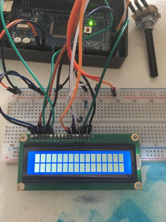
youtube
The reason behind it was very simple. In the process of debugging, I realized I have mistaken the place of one of the pins. After I rearranged the pins, the LCD Screen worked properly.

After that I added one ServoMotor and system’s visualization looked like this:

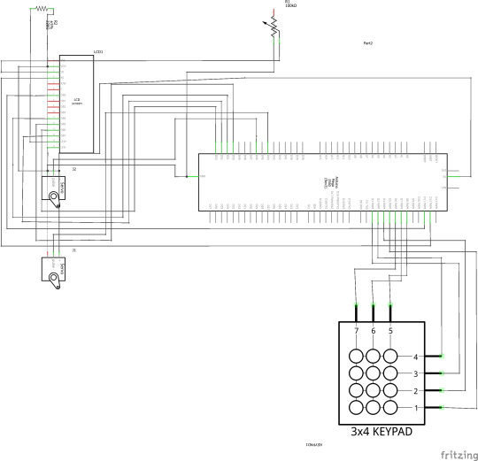
Respectively, the schematic was this:

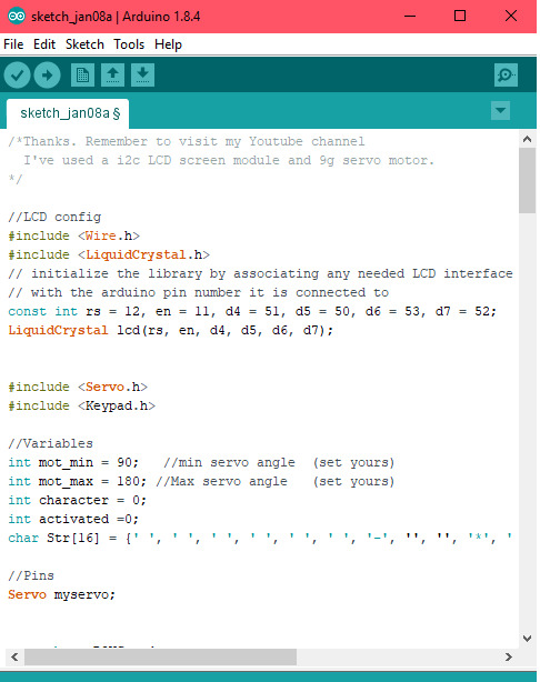
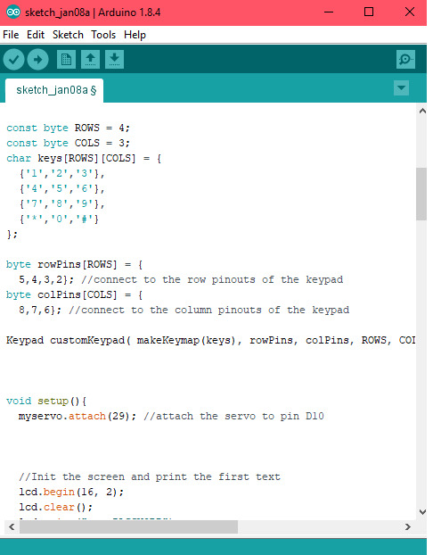
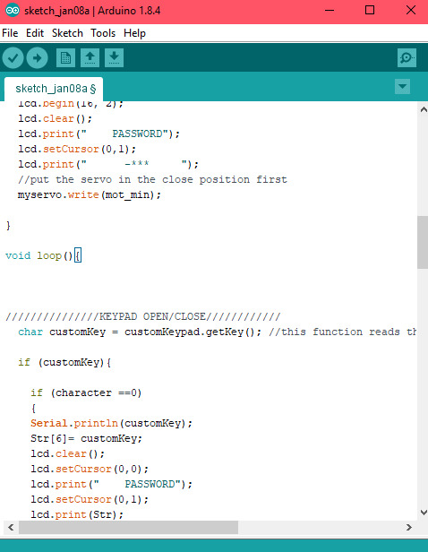
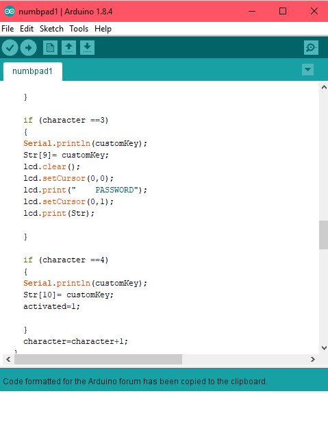
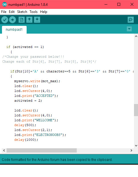
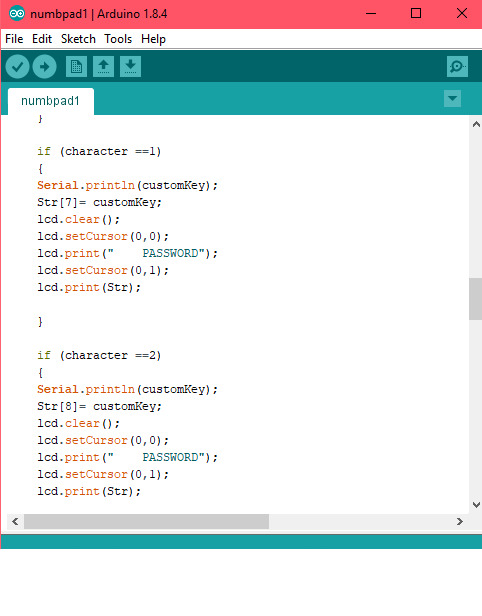
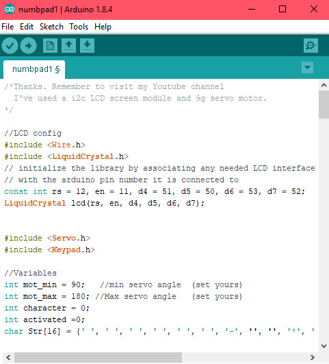
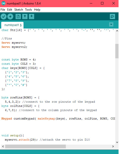
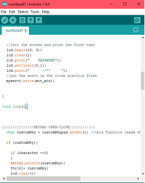
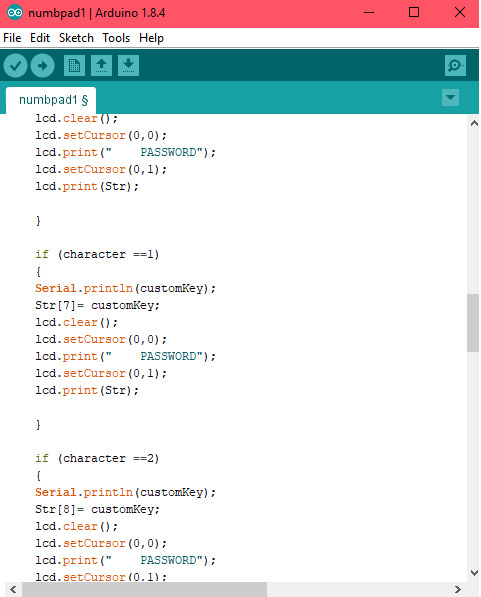
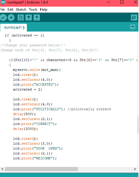
The coding part required some special attention since I hadn’t had any real experience with coding a microcontroller but overall, reflecting on it now, the code itself is not very difficult. It’s a combination with the code for a ServoMotor, an LCD Screen and an “If” function. What was new, was the code that activated the Numberpad and adding the specific library for it. For the first try outs, I played around with what could be “printed” on the screen and the password but the basis of the code looks like this:
Here is a video of how it works:
youtube
I proceed with the adding of the next ServoMotor. The visualzation for it follows:

The schematic is the same was the previous one with the addition of one more motor.
The code, as well, stayed the same. The only one difference was the lines for an additional ServoMotor with specifiying to which pins of the Arduino is connected.
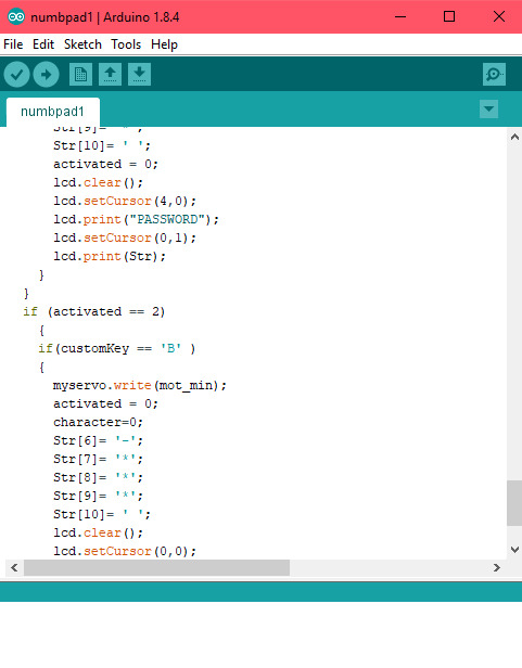
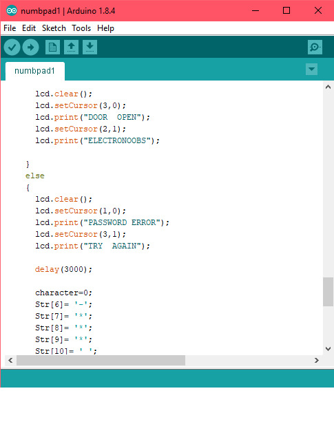
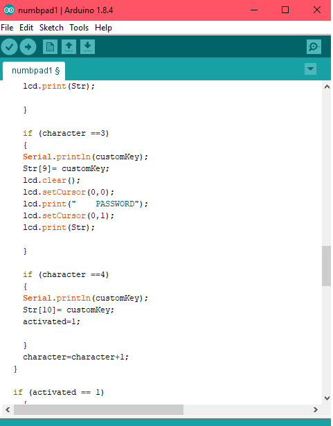
My initial idea was to use two ServoMotors that pull the mechanical lock. Unfortunatley, the ServoMotors were too small and not powerful enough to activate a mechanical lock. What came to my mind as an idea was to use only one motor (based on the schematic, the vizualization mentioned above) and to mimic a lock with a small piece of metal, glued to the ServoMotor. I adapted the code to the wing of the ServoMotor moves 90 degrees up, when the correct password is entered (imitation an opening) and then going back, when pressed # (imitation closing). Of course, when the password is incorrect, nothing was happening except for a notifying message on the LCD Screen.
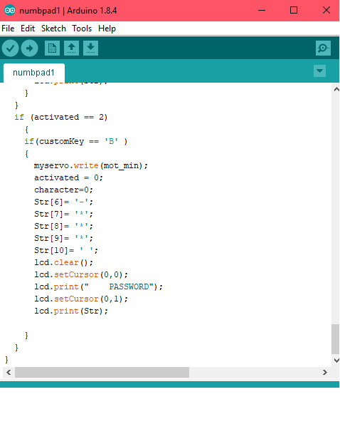
In conclusion for the final project I used one ServoMotors as shown on the first visualization I mentioned earlier on my post. The code for this follows:
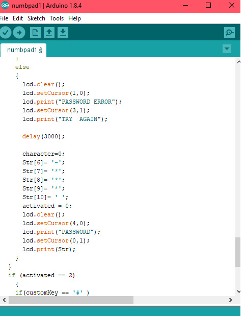
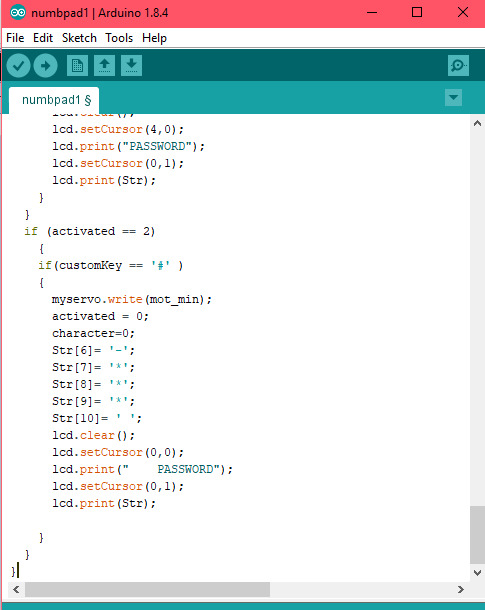
Lastly, I post a video that shows how my projects works in practice.
youtube
Overall,
0 notes
Text
Work with Buzzer and a TactSwitch
Recently, we worked with a Buzzer and a Tact Switch and learned how to combine both in a one circuit. Here is the schematic:


The essence of this system is that everytime you press the TactSwitch, the Buzzer makes a sound.
0 notes
Text
Work with LCD Screen and LED Matrix 8x8
Before the Christmas break, we worked with some premade codes from The Arduino Library for and LCD Screens. Wth them we managed to successfully write different words on it. Here is the result:
youtube
youtube
After that we learned how to use an LED Matrix 8x8, again with premade codes for the Arduino Library. Here is the result:


0 notes
Text
Assignment 2; Design and program a circuit with a certain specifications
For the second assignment in our Electronics class, we needed to work with potentiometers and to understand their usage.
Potentiometers are three-terminal (ends) resistors with a sliding or rotating contact that forms an adjustable voltage divider. In certain occasions it could work a variable resistor or rheostat.
Potentiometers were widely used in technology produced during the 90s. Usually they were, and in some cases are still, a tool for audio control or to control brightness and colour adjustments of the picture in old-school TVs.
In our case, we needed to create a circuit with the following specifications:
- at least one tact switch - at least one potentiometer or a LDR - at least four LEDs - use the functions digitalRead/analogRead
I decided to include 1 switch, 1 potentiometer and 4 LED lights.
Firstly, the switch had to be tested individually, in order to see if it’s working. The following code served that purpose:

The next step was to try out the LEDs, using this code:
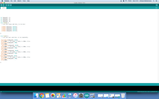
Finally, the potentionmeter was included. Unfortunately the potentiometer was broken and even through the usage of multiple code, it still wasn’t functioning. One of the codes that was used follows:
Some photos of the experiment as well:


Update
After some tries and collaborating with Yara and Krystina, we managed to get the potentiometer working. We used 4 LEDs and a switch for the purpose and we were able to control them with the potentiometer. We built a circuit based on this schematic:


After we built the circuit, we started working on a code, combining commands for all the components.
Result of the assignment:
youtube
0 notes
Text
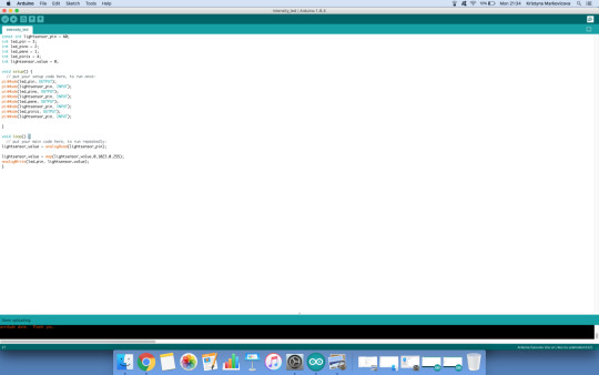
Assignment 1; Working with digitalRead, Serial.print, Serial.println
For this assignment I worked with Yara and Krystina as well. We needed to experiment with the functions Serial.print, digitalRead and Serial.println in Arduino.
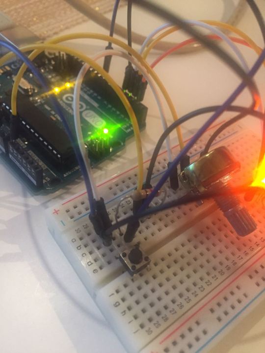
Firstly, again, we started with drawing the schematic of the desired circuit.

After we had more clarity, we started building the circuit.
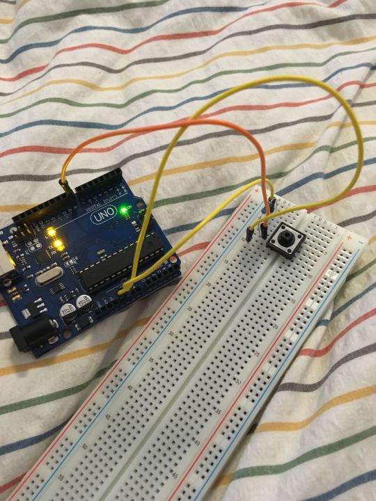
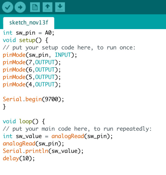
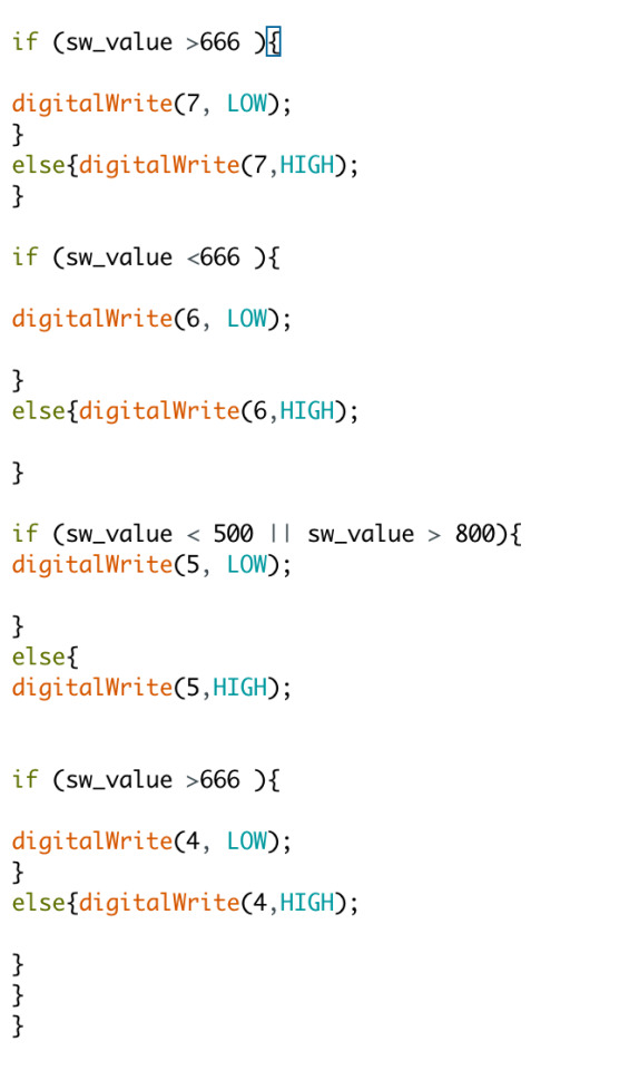
In order for our switch button to work, we needed to write a specific code in the Arduino’s software.
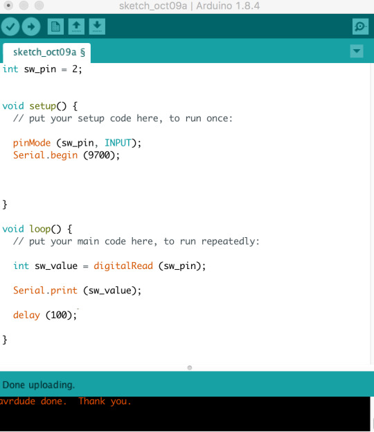
Our main aim in using these functions was to be able to change the values we see on the screen through clicking the button. Anytime you haven’t clicked the button, the program knows that the shown value would be 0. The moment you press the button (and hold it), the value changes to 1.
Here is a video of the result:
youtube
0 notes
Text
Assignment 1; Working with DigitalWrite and AnalogWrite
For this assignment I work in a group with Krystina and Yara. Through this exercise we explore the work with Arduino’s features. We created a circuit with two LEDs, using the functions digitalWrite and analogWrite.
As a start of our process we draw a schematic of the circuits we were about to program.


After we draw the schematic, we had a clearer idea on how to proceed. We started building it on the breadboard.

The second step consisted of writing the code for the Arduino’s software, on which we worked in class.

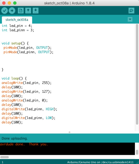
After that we uploaded the code and the Arduino applied it to the circuit.
Here is a video of our assignment.
https://youtu.be/1QziaZfRVg0
0 notes
Text
Tuseday inspiration
While researching the field of technology and its use in the art world, I came across an interesting project by the TechLab in Tokyo. Their Homogenizing and Transforming World summerizes how electronics interfere with creativity.
A brief description of the project follows "Individual balls floating within an enclosed space communicate to each other via wireless connection. They change color and emit different sounds when touched by visitors or bump into each other or other objects. The balls send color information to other balls which in turn spread the information to other balls, changing all the balls to the same color. The piece is a metaphor for the internet and globalization in general. People act as intermediaries for information which so quickly travels via the internet globally, transforming the world in an instant and unifying at the same time."
youtube
0 notes