
Don't wanna be here? Send us removal request.
Statistics
We looked inside some of the posts by experimentsportfolio and here's what we found interesting.
Average Info
Notes Per Post
0
Likes Per Post
0
Reblog Per Post
0
Reply Per Post
0
Time Between Posts
4 minutes
Number of Posts By Type
Text
17
Last Seen Tumblr Blogs


Fun Fact
Users from the US are the majority of Tumblr visitors.
Text
The video demos for the final version of Memory Game won't load, however you can view videos showcasing the games reaction to correct and incorrect inputs in the videos and pictures folder of this google drive:
https://drive.google.com/drive/folders/1DeyMtzdrU9DBoFqQvn03eiNW19myhHCK?usp=sharing
Screen captures and code files can also be found on the drive.
0 notes
Text
I’ve coded the program in a way were the check process I mentioned doesn’t take the form of a function. Rather, I’ve put the Game Display and Game Solve functions in a while loop. It loops whilst a bool variable called success is true. This bool is set to false in the condition the user gets an incorrect input.
When the while loop is broken, the game is reset in a new function I’ve written call Initialize Game. This runs before every game. It is responsible for resetting the success bool and some code that now generates a random sequence in the gameSolve array.
0 notes
Text

If the condition (correct input) is met, then a similar case statement to the one in Game Display helps visualize the player’s inputs.
If an input does not match the sequence, the level is reset to the first and ‘return 0’ boots the process out of the function. However, if the whole level is cleared, the level integer increments before ending the function.
Either way, Game Display is run again, the only difference is the updated level position.
0 notes
Text

An if statement is used to compare the player’s input with the sequence.
0 notes
Text

With that done, I turned my attention to Game Solve. For all of the experiments performed so far, the code is in a perpetual loop, constantly checking for inputs or repeating executions. I needed a model that halted the code until the user pressed a key. For that, I made a while loop. While there is no input (making use of the NO_KEY), get the value of key (if key remains as NO_KEY, this repeats indefinitely).
0 notes
Text
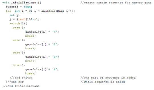
To start coding the game, I decided the easiest way to test it was to create a pre-defined sequence, or game solution, rather than have the sequence evolve randomly. I hope to change this once the foundations of the game a sorted.
In planning, I broke up the process of the game into 3 sections, likely to become functions code.
1. Game Display: display the sequence for the current level.
2. Game Solve: wait for the user to input the sequence.
3. Game Check: check if the user has entered the right sequence.
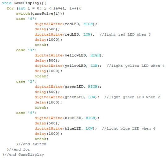
I began with writing the Game Display function, where the sequence is:
Blue, Green, Blue, Red, Red, Green, Yellow, Blue, Green, Red. Level is initialized as 10 (max level) for the purpose the sequence demo.
The code above executes the description.
0 notes
Text

The yellow and red LEDs, particularly the former, were very dim in comparison to the others. I’m not sure if it’s the arrangement of the circuit or the absence of resisters, but is defiantly an area to improve on. I also customized the keypad to have the keys resemble the colours of the memory game.
0 notes
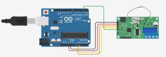
Text
Testing the interactivity of the membrane switch module.
0 notes
Text

Memory Game
Description:
Building of the experiment where I used the direction of an analog stick to determine which LED to light up on a bread board, I decided for my final artefact I’d make a colour based memory game.
In the game, one of the four different LEDs on the board will light up, and the player has to activate that same light to proceed to the next level. The next level will light the same LED as before, and then have another flash up afterwards: the user will have to repeat the sequence. Subsequent levels will repeat the sequence, adding a new colour to it each level, and the player’s goal is to remember the sequence and input it.
Components:
· Elegoo Uno R3
· USB Cable
· Breadboard
· Membrane Switch Module
· 17x Male-to-Male Jumper Wires
· Red, Yellow, Green and Blue LEDS
I decided to make an array to store the colour values of the sequence which would be the back bone of the game. However, I soon realized that to compare the user’s analogue input with an array that can only store integers and characters would be very complicated. Therefore, I opted to change the input, from the joystick that has analogue input, to the membrane keypad which has digital inputs.
The membrane keypad operates like a number of switches in a parallel circuit. Once a key is pushed down, a connection is made for the current. In this approach, I have set the red LED to the key 8, yellow to 4, green to 2 and 6 to blue (the arrangement of buttons is similar to the directional buttons on a typical game consul controller). Note that the keys are stored as characters instead of integers.
In code, the keypad is essentially stored as a class. In order to access the keypad, the customKeyad class is defined by:
· hexaKeys: a two-dimensional array with the characters labelled on the pad for key mapping.
· Two fixed integers, both of 4, representing the number of both rows and columns (4x4).
· The numbered pins the wires are physically attached to.
0 notes

Text
To better visualize the interactive code, I proceeded to wire four differently coloured LED lights, in the four cardinal positions, and have them light up based on the direction of the joystick. The code stayed the same relatively, only changing out the lines that write to the serial to digital writes for LED on.
0 notes
Text
The code provided in lesson 13 continuously reads the position data of the analogy stick and prints them in the serial window. I decided to change it so that the general direction of the stick would be printed instead. This meant drawing zones to represent up, down, left and right and figuring out what positional coordinates fell in which direction. This would be the first time for me writing to the serial window.
Using an extended if statement allows us to cover the four different states. It’s up and down states are determined by the value of the y coordinate and right and left by the x coordinate. When determining the position of the stick, I gave it a value buffer of 100 because I found that with the level of accuracy of the stick, leaving it in the centre didn’t mean it was always at 512,512 necessarily.
0 notes
Text

Joy Stick
Description:
I was curious to see how and if I could make the joystick work as an input device. The device is like an analog input, where there are plenty of different states it can be in, as opposed to digital, which only has an on or off state.
Components:
· Elegoo Uno R3
· USB Cable
· Breadboard
· Joystick Module
· 4x Female-to-Male Jumper Wires
· 9x Male-to-Male Jumper Wires
· Red, Yellow, Green and Blue LEDS
The positional data of the analogue stick is read as two values, an x and a y coordinate, much like a flat geometric graph. With the analogue stick provided in the Arduino kit, the positional data has a range of 1024 and that many unique values can be stored in 11bits (2^11 ). This means that, for example, when the stick pushed all the way away from the user, it reads a y-0, and if it is pulled all the way towards the user, it reads as y-1024. A stick in the middle reads a value of 512. The same logic goes for the x axis as well.
0 notes
